


Installation and Operation Manual
RIC-E1
E1 Interface Converter
Order from: Cutter Networks |
Ph:727-398-5252/Fax:727-397-9610 |
www.bestdatasource.com |
Order from: Cutter Networks |
Ph:727-398-5252/Fax:727-397-9610 |
www.bestdatasource.com |

RIC-E1
E1 Interface Converter
Installation and Operation Manual
Notice
This manual contains information that is proprietary to RAD Data Communications Ltd. ("RAD"). No part of this publication may be reproduced in any form whatsoever without prior written approval by RAD Data Communications.
Right, title and interest, all information, copyrights, patents, know-how, trade secrets and other intellectual property or other proprietary rights relating to this manual and to the RIC-E1 and any software components contained therein are proprietary products of RAD protected under international copyright law and shall be and remain solely with RAD.
RIC-E1 is a registered trademark of RAD. No right, license, or interest to such trademark is granted hereunder, and you agree that no such right, license, or interest shall be asserted by you with respect to such trademark.
You shall not copy, reverse compile or reverse assemble all or any portion of the Manual or the RIC-E1. You are prohibited from, and shall not, directly or indirectly, develop, market, distribute, license, or sell any product that supports substantially similar functionality as the RIC-E1, based on or derived in any way from the RIC-E1. Your undertaking in this paragraph shall survive the termination of this Agreement.
This Agreement is effective upon your opening of the RIC-E1 package and shall continue until terminated. RAD may terminate this Agreement upon the breach by you of any term hereof. Upon such termination by RAD, you agree to return to RAD the RIC-E1 and all copies and portions thereof.
For further information contact RAD at the address below or contact your local distributor.
|
International Headquarters |
U.S. Headquarters |
|
|
RAD Data Communications Ltd. |
RAD Data Communications Inc. |
|
|
24 Raoul Wallenberg St. |
900 Corporate Drive |
|
|
Tel Aviv 69719 Israel |
Mahwah, NJ 07430 USA |
|
|
Tel: 972-3-6458181 |
Tel: (201) 529-1100, Toll free: 1-800-444-7234 |
|
|
Fax: 972-3-6498250 |
Fax: (201) 529-5777 |
|
|
E-mail: market@rad.com |
E-mail: market@radusa.com |
|
|
|
|
|
© 1991–2003 RAD Data Communications Ltd. |
Publication No. 269-200-12/04 |
||
Order from: Cutter Networks |
Ph:727-398-5252/Fax:727-397-9610 |
www.bestdatasource.com |
Limited Warranty
RAD warrants to DISTRIBUTOR that the hardware in the RIC-E1 to be delivered hereunder shall be free of defects in material and workmanship under normal use and service for a period of twelve (12) months following the date of shipment to DISTRIBUTOR.
If, during the warranty period, any component part of the equipment becomes defective by reason of material or workmanship, and DISTRIBUTOR immediately notifies RAD of such defect, RAD shall have the option to choose the appropriate corrective action: a) supply a replacement part, or b) request return of equipment to its plant for repair, or c) perform necessary repair at the equipment's location. In the event that RAD requests the return of equipment, each party shall pay one-way shipping costs.
RAD shall be released from all obligations under its warranty in the event that the equipment has been subjected to misuse, neglect, accident or improper installation, or if repairs or modifications were made by persons other than RAD's own authorized service personnel, unless such repairs by others were made with the written consent of RAD.
The above warranty is in lieu of all other warranties, expressed or implied. There are no warranties which extend beyond the face hereof, including, but not limited to, warranties of merchantability and fitness for a particular purpose, and in no event shall RAD be liable for consequential damages.
RAD shall not be liable to any person for any special or indirect damages, including, but not limited to, lost profits from any cause whatsoever arising from or in any way connected with the manufacture, sale, handling, repair, maintenance or use of the RIC-E1, and in no event shall RAD's liability exceed the purchase price of the RIC-E1.
DISTRIBUTOR shall be responsible to its customers for any and all warranties which it makes relating to RIC-E1 and for ensuring that replacements and other adjustments required in connection with the said warranties are satisfactory.
Software components in the RIC-E1 are provided "as is" and without warranty of any kind. RAD disclaims all warranties including the implied warranties of merchantability and fitness for a particular purpose. RAD shall not be liable for any loss of use, interruption of business or indirect, special, incidental or consequential damages of any kind. In spite of the above RAD shall do its best to provide error-free software products and shall offer free Software updates during the warranty period under this Agreement.
RAD's cumulative liability to you or any other party for any loss or damages resulting from any claims, demands, or actions arising out of or relating to this Agreement and the RIC-E1 shall not exceed the sum paid to RAD for the purchase of the RIC-E1. In no event shall RAD be liable for any indirect, incidental, consequential, special, or exemplary damages or lost profits, even if RAD has been advised of the possibility of such damages.
This Agreement shall be construed and governed in accordance with the laws of the State of Israel.
Order from: Cutter Networks |
Ph:727-398-5252/Fax:727-397-9610 |
www.bestdatasource.com |

General Safety Instructions
The following instructions serve as a general guide for the safe installation and operation of telecommunications products. Additional instructions, if applicable, are included inside the manual.
Safety Symbols
This symbol may appear on the equipment or in the text. It indicates potential safety hazards regarding product operation or maintenance to
operator or service personnel.
Warning
Danger of electric shock! Avoid any contact with the marked surface while the product is energized or connected to outdoor telecommunication lines.
.
Protective earth: the marked lug or terminal should be connected to the building protective earth bus.
|
Some products may be equipped with a laser diode. In such cases, a label |
|
|
with the laser class and other warnings as applicable will be attached near |
|
Warning |
the optical transmitter. The laser warning symbol may be also attached. |
|
Please observe the following precautions: |
||
|
•Before turning on the equipment, make sure that the fiber optic cable is intact and is connected to the transmitter.
•Do not attempt to adjust the laser drive current.
•Do not use broken or unterminated fiber-optic cables/connectors or look straight at the laser beam.
•The use of optical devices with the equipment will increase eye hazard.
•Use of controls, adjustments or performing procedures other than those specified herein, may result in hazardous radiation exposure.
ATTENTION: The laser beam may be invisible!
Always observe standard safety precautions during installation, operation and maintenance of this product. Only qualified and authorized service personnel should carry out adjustment, maintenance or repairs to this product. No installation, adjustment, maintenance or repairs should be performed by either the operator or the user.
Order from: Cutter Networks |
Ph:727-398-5252/Fax:727-397-9610 |
www.bestdatasource.com |
Handling Energized Products
General Safety Practices
Do not touch or tamper with the power supply when the power cord is connected. Line voltages may be present inside certain products even when the power switch (if installed) is in the OFF position or a fuse is blown. For DC-powered products, although the voltages levels are usually not hazardous, energy hazards may still exist.
Before working on equipment connected to power lines or telecommunication lines, remove jewelry or any other metallic object that may come into contact with energized parts.
Unless otherwise specified, all products are intended to be grounded during normal use. Grounding is provided by connecting the mains plug to a wall socket with a protective earth terminal. If an earth lug is provided on the product, it should be connected to the protective earth at all times, by a wire with a diameter of 18 AWG or wider. Rack-mounted equipment should be mounted only in earthed racks and cabinets.
Always make the ground connection first and disconnect it last. Do not connect telecommunication cables to ungrounded equipment. Make sure that all other cables are disconnected before disconnecting the ground.
Connection of AC Mains
Make sure that the electrical installation complies with local codes. Always connect the AC plug to a wall socket with a protective ground.
The maximum permissible current capability of the branch distribution circuit that supplies power to the product is 16A. The circuit breaker in the building installation should have high breaking capacity and must operate at short-circuit current exceeding 35A.
Always connect the power cord first to the equipment and then to the wall socket. If a power switch is provided in the equipment, set it to the OFF position. If the power cord cannot be readily disconnected in case of emergency, make sure that a readily accessible circuit breaker or emergency switch is installed in the building installation.
Connection of DC Mains
Unless otherwise specified in the manual, the DC input to the equipment is floating in reference to the ground. Any single pole can be externally grounded.
Due to the high current capability of DC mains systems, care should be taken when connecting the DC supply to avoid short-circuits and fire hazards.
DC units should be installed in a restricted access area, i.e. an area where access is authorized only to qualified service and maintenance personnel.
Make sure that the DC supply is electrically isolated from any AC source and that the installation complies with the local codes.
The maximum permissible current capability of the branch distribution circuit that supplies power to the product is 16A. The circuit breaker in the building installation should have high breaking capacity and must operate at short-circuit current exceeding 35A.
Before connecting the DC supply wires, ensure that power is removed form the DC circuit. Locate the circuit breaker of the panel board that services the equipment and switch it to the OFF position. When connecting the DC supply wires, first connect the ground wire to the corresponding terminal, then the positive pole and last the negative pole. Switch the circuit breaker back to the ON position.
A readily accessible disconnect device that is suitably rated and approved should be incorporated in the building installation.
Order from: Cutter Networks |
Ph:727-398-5252/Fax:727-397-9610 |
www.bestdatasource.com |

Connection of Data and Telecommunications Cables
Data and telecommunication interfaces are classified according to their safety status.
The following table lists the status of several standard interfaces. If the status of a given port differs from the standard one, a notice will be given in the manual.
Ports |
Safety Status |
|
|
|
|
V.11, V.28, V.35, V.36, RS-530, |
SELV Safety Extra Low Voltage: |
|
X.21, 10 BaseT, 100 BaseT, |
Ports which do not present a safety hazard. Usually |
|
Unbalanced E1, E2, E3, STM, DS-2, |
||
up to 30 VAC or 60 VDC. |
||
DS-3, S-Interface ISDN, Analog voice |
||
|
||
E&M |
|
xDSL (without feeding voltage), Balanced E1, T1, Sub E1/T1
TNV-1 Telecommunication Network Voltage-1:
Ports whose normal operating voltage is within the limits of SELV, on which overvoltages from telecommunications networks are possible.
FXS (Foreign Exchange Subscriber) |
TNV-2 |
Telecommunication Network Voltage-2: |
|
|
Ports whose normal operating voltage exceeds the |
|
|
limits of SELV (usually up to 120 VDC or telephone |
|
|
ringing voltages), on which overvoltages from |
|
|
telecommunication networks are not possible. These |
|
|
ports are not permitted to be directly connected to |
|
|
external telephone and data lines. |
|
|
|
FXO (Foreign Exchange Office), xDSL |
TNV-3 |
Telecommunication Network Voltage-3: |
(with feeding voltage), U-Interface |
|
Ports whose normal operating voltage exceeds the |
ISDN |
|
|
|
limits of SELV (usually up to 120 VDC or telephone |
|
|
|
|
|
|
ringing voltages), on which overvoltages from |
|
|
telecommunication networks are possible. |
|
|
|
Always connect a given port to a port of the same safety status. If in doubt, seek the assistance of a qualified safety engineer.
Always make sure that the equipment is grounded before connecting telecommunication cables. Do not disconnect the ground connection before disconnecting all telecommunications cables.
Some SELV and non-SELV circuits use the same connectors. Use caution when connecting cables. Extra caution should be exercised during thunderstorms.
When using shielded or coaxial cables, verify that there is a good ground connection at both ends. The earthing and bonding of the ground connections should comply with the local codes.
The telecommunication wiring in the building may be damaged or present a fire hazard in case of contact between exposed external wires and the AC power lines. In order to reduce the risk, there are restrictions on the diameter of wires in the telecom cables, between the equipment and the mating connectors.
Order from: Cutter Networks |
Ph:727-398-5252/Fax:727-397-9610 |
www.bestdatasource.com |
Caution |
To reduce the risk of fire, use only No. 26 AWG or larger telecommunication line cords. |
|
|
||
Attention |
|
|
|
||
Pour réduire les risques s’incendie, utiliser seulement des conducteurs de |
||
|
||
|
télécommunications 26 AWG ou de section supérieure. |
|
|
|
Some ports are suitable for connection to intra-building or non-exposed wiring or cabling only. In such cases, a notice will be given in the installation instructions.
Do not attempt to tamper with any carrier-provided equipment or connection hardware.
Electromagnetic Compatibility (EMC)
The equipment is designed and approved to comply with the electromagnetic regulations of major regulatory bodies. The following instructions may enhance the performance of the equipment and will provide better protection against excessive emission and better immunity against disturbances.
A good earth connection is essential. When installing the equipment in a rack, make sure to remove all traces of paint from the mounting points. Use suitable lock-washers and torque. If an external grounding lug is provided, connect it to the earth bus using braided wire as short as possible.
The equipment is designed to comply with EMC requirements when connecting it with unshielded twisted pair (UTP) cables. However, the use of shielded wires is always recommended, especially for high-rate data. In some cases, when unshielded wires are used, ferrite cores should be installed on certain cables. In such cases, special instructions are provided in the manual.
Disconnect all wires which are not in permanent use, such as cables used for one-time configuration.
The compliance of the equipment with the regulations for conducted emission on the data lines is dependent on the cable quality. The emission is tested for UTP with 80 dB longitudinal conversion loss (LCL).
Unless otherwise specified or described in the manual, TNV-1 and TNV-3 ports provide secondary protection against surges on the data lines. Primary protectors should be provided in the building installation.
The equipment is designed to provide adequate protection against electro-static discharge (ESD). However, it is good working practice to use caution when connecting cables terminated with plastic connectors (without a grounded metal hood, such as flat cables) to sensitive data lines. Before connecting such cables, discharge yourself by touching earth ground or wear an ESD preventive wrist strap.
FCC-15 User Information
This equipment has been tested and found to comply with the limits of the Class A digital device, pursuant to Part 15 of the FCC rules. These limits are designed to provide reasonable protection against harmful interference when the equipment is operated in a commercial environment. This equipment generates, uses and can radiate radio frequency energy and, if not installed and used in accordance with the Installation and Operation manual, may cause harmful interference to the radio communications. Operation of this equipment in a residential area is likely to cause harmful interference in which case the user will be required to correct the interference at his own expense.
Order from: Cutter Networks |
Ph:727-398-5252/Fax:727-397-9610 |
www.bestdatasource.com |
Canadian Emission Requirements
This Class A digital apparatus meets all the requirements of the Canadian Interference-Causing Equipment Regulation.
Cet appareil numérique de la classe A respecte toutes les exigences du Règlement sur le matériel brouilleur du Canada.
|
Warning per EN 55022 (CISPR-22) |
Warning |
|
This is a class A product. In a domestic environment, this product may cause |
|
|
radio interference, in which case the user will be required to take adequate |
|
measures. |
|
|
|
|
Avertissement |
Cet appareil est un appareil de Classe A. Dans un environnement résidentiel, cet |
appareil peut provoquer des brouillages radioélectriques. Dans ces cas, il peut |
|
|
être demandé à l’utilisateur de prendre les mesures appropriées. |
|
|
|
|
|
Dieses ist ein Gerät der Funkstörgrenzwertklasse A. In Wohnbereichen können |
Achtung |
bei Betrieb dieses Gerätes Rundfunkströrungen auftreten, in welchen Fällen der |
|
Benutzer für entsprechende Gegenmaßnahmen verantwortlich ist. |
Order from: Cutter Networks |
Ph:727-398-5252/Fax:727-397-9610 |
www.bestdatasource.com |

Declaration of Conformity
Manufacturer's Name: |
RAD Data Communications Ltd. |
Manufacturer's Address: |
24 Raoul Wallenberg St. |
|
Tel Aviv 69719 |
|
Israel |
declares that the products: |
|
Product Names: |
RIC-E1, RIC-T1 |
conform to the following standard(s) or other normative document(s):
EMC: |
EN 55022: 1998 |
Information technology equipment – Radio disturbance |
|
|
characteristics – Limits and methods of measurement. |
|
EN 50024: 1998 |
Information technology equipment – Immunity characteristics |
|
|
– Limits and methods of measurement. |
Safety: |
EN 60950: 2000 |
Safety of information technology equipment. |
Supplementary Information:
The products herewith comply with the requirements of the EMC Directive 89/336/EEC, the Low Voltage Directive 73/23/EEC and the R&TTE Directive 1999/5/EC for wired equipment. The products were tested in a typical configuration.
Tel Aviv, 9th October, 2002
Haim Karshen
VP Quality
European Contact: RAD Data Communications GmbH, Otto-Hahn-Str. 28-30,
85521 Ottobrunn-Riemerling, Germany
Order from: Cutter Networks |
Ph:727-398-5252/Fax:727-397-9610 |
www.bestdatasource.com |
Quick Start Guide
If you are familiar with RIC-E1, use this guide to prepare it for operation.
1.Installing RIC-E1
Open the RIC-E1 case by sliding the blue side panel forward and releasing the two screws located on the bottom panel at the rear end of the unit.
Setting the Internal Jumpers
Set the internal jumpers. For the standalone RIC-E1 jumpers, see the first table below. For the RIC-E1/R jumpers see the second table.
Jumper |
Description |
Values |
Default Setting |
|
|
|
|
JP1, JP2, JP3, JP4, |
Select the E1 interface type |
BAL – Balanced interface |
BAL |
JP6 |
|
(RJ-45 connector) |
|
|
|
BNC – Unbalanced interface (BNC |
|
|
|
coax connectors) |
|
|
|
|
|
TX & RX CODE, |
Selects the transmit and |
AMI – Jumper plug is installed |
|
JP9 |
receive coding |
HDB3 – Jumper plug is not installed |
HDB3 |
|
|
||
|
|
|
|
TIMING, J4 |
Selects the clock reference |
RCV (pin 4) – Receive clock |
RCV |
|
|
EXT (pin 5) – External clock |
|
|
|
INT (pin 6) – Internal clock |
|
Note: Units with the IR-ETH, IR-ETH/V and IR-IP interface modules support only receive and internal clocks.
ANA LOOP, JP11 Controls the local analog |
LOC – Activates the local analog |
|
loopback activation |
loopback |
|
|
DTE – Allows the activation of the |
DTE |
|
local analog loopback via DTE |
|
|
|
|
Installing RIC-E1 |
1 |
Order from: Cutter Networks |
Ph:727-398-5252/Fax:727-397-9610 |
www.bestdatasource.com |

|
Quick Start Guide |
|
RIC-E1 Installation and Operation Manual |
||
|
|
|
|
|
|
|
|
|
|
|
|
|
Jumper |
Description |
Values |
Default Setting |
|
|
|
|
|
|
|
|
JP2, JP3 |
Select the E1 interface type |
BALANCE – Balanced interface |
BALANCE |
|
|
|
|
(RJ-45 connector) |
|
|
|
|
|
UNBALANCE – Unbalanced |
|
|
|
|
|
interface (BNC |
|
|
|
|
|
coax connectors) |
|
|
|
|
|
|
|
|
|
ALB DTE, JP4 |
Enables local analog |
EN – The local analog loopback |
|
|
|
|
loopback activation from |
activation from the DTE is |
|
|
|
|
the DTE (via pin 18 for |
enabled |
|
|
|
|
RS-530 or via pin “JJ” for |
DIS – The local analog loopback |
DIS |
|
|
|
V.35) |
activation from the DTE is |
|
|
disabled
Note: The JP4 jumper is not available for RIC-E1/R cards with X.21 or Ethernet interfaces.
PNL SW, JP5 |
Enables activation of the |
|
local analog loopback via |
|
the front panel pushbutton |
EN – The LLB can be activated via EN the front panel
DIS – The LLB cannot be activated via the front panel
Note: The JP5 jumper is not available for RIC-E1/R cards with IR-ETH and IR-ETH/V interface modules.
For RIC-E1/R with IR-IP interface module, the JP5 jumper serves for enabling or disabling the IP LEARN pushbutton.
TX&RX CODE, JP6 |
Selects the data receive |
HDB3 |
HDB3 |
|
and transmit coding |
AMI |
|
|
|
|
|
TIMING SEL, J2 |
Selects the clock reference |
RCV – Receive clock |
RCV |
|
|
EXT – External clock |
|
|
|
INT – Internal clock |
|
Note: Units with the IR-ETH, IR-ETH/V and IR-IP interface modules support only receive and internal clocks.
CHASS GND, J3 Controls the connection between the RIC-E1/R signal ground and the frame (chassis) ground
CON – Signal ground is |
CON |
connected to the frame |
|
ground |
|
DISCON – Signal ground is |
|
disconnected from the |
|
frame ground |
|
Connecting the Cables
To connect cables:
1.Connect the E1 line interface.
2.Connect the DTE interface.
3.Connect the power cable (first to the converter, then to the mains supply). The PWR LED lights when power is connected.
2.Operating RIC-E1
RIC-E1 operates entirely unattended except when performing system tests.
2 |
Operating RIC-E1 |
Order from: Cutter Networks |
Ph:727-398-5252/Fax:727-397-9610 |
www.bestdatasource.com |
|
|
Contents |
|
Chapter 1. Introduction |
|
|
|
1.1 |
Overview..................................................................................................................... |
|
1-1 |
|
Versions................................................................................................................................ |
|
1-1 |
|
Application ........................................................................................................................... |
|
1-2 |
1.2 |
Physical Description..................................................................................................... |
|
1-2 |
1.3 |
Functional Description................................................................................................. |
|
1-3 |
|
Functional Block Diagram ..................................................................................................... |
1-3 |
|
|
Timing Reference.................................................................................................................. |
|
1-3 |
|
Diagnostics ........................................................................................................................... |
|
1-3 |
1.4 |
Technical Specifications............................................................................................... |
|
1-4 |
Chapter 2. Installation and Setup |
|
|
|
2.1 |
Site Requirements and Prerequisites ............................................................................ |
2-1 |
|
2.2 |
Package Contents ........................................................................................................ |
|
2-1 |
2.3 |
Configuring RIC-E1 ...................................................................................................... |
|
2-2 |
|
Setting the Jumpers............................................................................................................... |
|
2-2 |
|
Connecting the Interfaces ..................................................................................................... |
2-4 |
|
|
Connecting the Power .......................................................................................................... |
|
2-5 |
Chapter 3. Operation |
|
|
|
3.1 |
Front Panel Indicators .................................................................................................. |
|
3-1 |
3.2 |
Operating Instructions ................................................................................................. |
|
3-2 |
|
Turning On........................................................................................................................... |
|
3-2 |
|
Operating RIC-E1 ................................................................................................................. |
|
3-2 |
|
Turning Off........................................................................................................................... |
|
3-2 |
Chapter 4. Troubleshooting and Diagnostics |
|
||
4.1 |
Performing Local Analog Loopback.............................................................................. |
4-1 |
|
|
Activating Local Analog Loopback ......................................................................................... |
4-1 |
|
|
Deactivating Local Analog Loopback ..................................................................................... |
4-2 |
|
4.2 |
Troubleshooting........................................................................................................... |
|
4-2 |
4.3 |
Technical Support........................................................................................................ |
|
4-3 |
Chapter 5. RIC-E1/R Card |
|
|
|
5.1 |
ASM-MN-214 Card Cage............................................................................................. |
5-1 |
|
|
Line Connector..................................................................................................................... |
|
5-1 |
|
DTE Connector..................................................................................................................... |
|
5-1 |
5.2 |
Power Supply .............................................................................................................. |
|
5-3 |
|
AC Supply ............................................................................................................................ |
|
5-3 |
|
DC Supply............................................................................................................................ |
|
5-3 |
|
Power Supply with Redundancy............................................................................................ |
5-3 |
|
5.3 |
RIC-E1/R Front Panel ................................................................................................... |
|
5-4 |
5.4 |
Installing the RIC-E1/R Card......................................................................................... |
5-6 |
|
|
Setting Internal Jumpers and Switches ................................................................................... |
5-6 |
|
|
Installing RIC-E1/R into the ASM-MN-214 Card Cage ............................................................ |
5-7 |
|
|
Connecting the Interfaces ..................................................................................................... |
5-7 |
|
|
|
|
|
RIC-E1 Installation and Operation Manual |
|
i |
|
Order from: Cutter Networks |
Ph:727-398-5252/Fax:727-397-9610 |
www.bestdatasource.com |
|

Table of Contents
Appendix A. Interface Connector Wiring
Appendix B. IR-ETH Interface Module
Appendix C. IR-ETH/V Interface Module
Appendix D. IR-IP Interface Module
Appendix E. IR-X.21B Interface Module
|
|
List of Figures |
|
1-1. |
Typical Application................................................................................................................ |
1-2 |
|
1-2. |
RIC-E1 and RIC-T1, 3D View ................................................................................................ |
1-2 |
|
1-3. |
RIC-E1 Block Diagram ........................................................................................................... |
1-3 |
|
2-1. |
RIC-E1 |
Jumper Locations ....................................................................................................... |
2-3 |
2-2. |
RIC-E1 |
Rear Panel ................................................................................................................. |
2-4 |
3-1. |
RIC-E1 Front Panel................................................................................................................ |
3-1 |
|
4-1. |
RIC-E1 |
Local Loopback ......................................................................................................... |
4-1 |
5-1. ASM-MN-214 Rear Panel ...................................................................................................... |
5-2 |
||
5-2. |
RIC-E1/R with a Serial DTE Interface...................................................................................... |
5-4 |
|
5-3. |
RIC-E1/R with IR-ETH or IR-ETH/V ........................................................................................ |
5-4 |
|
5-4. |
RIC-E1/R with IR-IP ............................................................................................................... |
5-4 |
|
5-5. ASM-MN-214 Front Panel ..................................................................................................... |
5-5 |
||
5-6 |
RIC-E1/R PCB Layout ............................................................................................................. |
5-6 |
|
List of Tables
2-1. |
RIC-E1 |
Jumper Settings.......................................................................................................... |
2-3 |
3-1. |
RIC-E1 Front Panel LED Indicators ........................................................................................ |
3-1 |
|
4-1. |
RIC-E1 |
Troubleshooting......................................................................................................... |
4-2 |
5-1. |
RIC-E1/R Jumper Settings....................................................................................................... |
5-6 |
|
ii |
RIC-E1 Installation and Operation Manual |
Order from: Cutter Networks |
Ph:727-398-5252/Fax:727-397-9610 |
www.bestdatasource.com |

Chapter 1
Introduction
1.1 Overview
RIC-E1 is an interface converter. It converts unframed HDB3 or AMI data of ITU G.703 E1 balanced or unbalanced interface into an interchangeable DTE interface module.
RIC-E1 operates at 2048 kbps. It extracts data and the clock from the G.703 interface via a jitter attenuator to meet ITU G.823 requirements.
RIC-E1 acts as a line transceiver. It provides protection from over-voltage and over-current stress caused by lightning, power crosses and other noise sources.
Versions
The following versions of the RIC-E1 converter are available:
•RIC-E1 standalone unit
•RIC-E1/R – a plug-in card for installation in the ASM-MN-214, 19-inch modem/converter rack, holding up 14 cards (see Chapter 5 for the RIC-E1/R description).
DTE Interface
RIC-E1 can be ordered with one of the following DTE interfaces:
•V.35
•X.21
•V.36
•RS-530
•Ethernet:
IR-ETH (Ethernet bridge)
IR-ETH/V (Ethernet/Fast Ethernet bridge with VLAN support, replaces IR-ETH/QN)
IR-IP (IP router).
Power Supply
•AC power supply: 100 to 240 VAC
•DC power supply: 24 or -48 VDC.
Overview 1-1
Order from: Cutter Networks |
Ph:727-398-5252/Fax:727-397-9610 |
www.bestdatasource.com |

Chapter 1 Introduction |
RIC-E1 Installation and Operation Manual |
|
|
Application
RIC-E1 is typically used to connect between a G.703 network and a DTE. The DTE can be a multiplexer, a bridge, a router etc. Figure 1-1 illustrates a typical RIC-E1 application.
Network |
G.703 |
|
V.35 |
|
|
|
|
|
|
|
|
|
|
|
|
|
|
|
|
RIC-E1 |
|
|
|
|
|
|
|
|
|
|
|
|
|
|
|
DTE
Figure 1-1. Typical Application
1.2 Physical Description
A three-dimensional view of RIC-E1 and RIC-T1 is shown in Figure 1-2.
Figure 1-2. RIC-E1 and RIC-T1, 3D View
The RIC-E1 front panel contains LEDs that show the status of the unit. For more information, refer to Chapter 3.
The RIC-E1 rear panel contains the DTE interface, the G.703 link and the power connections. For more information, refer to Chapter 2.
A description of how to set the internal jumpers can be found in Chapter 2.
1-2 |
Physical Description |
Order from: Cutter Networks |
Ph:727-398-5252/Fax:727-397-9610 |
www.bestdatasource.com |
RIC-E1 Installation and Operation Manual |
Chapter 1 Introduction |
|
|
|
|
|
|
|
|
|
|
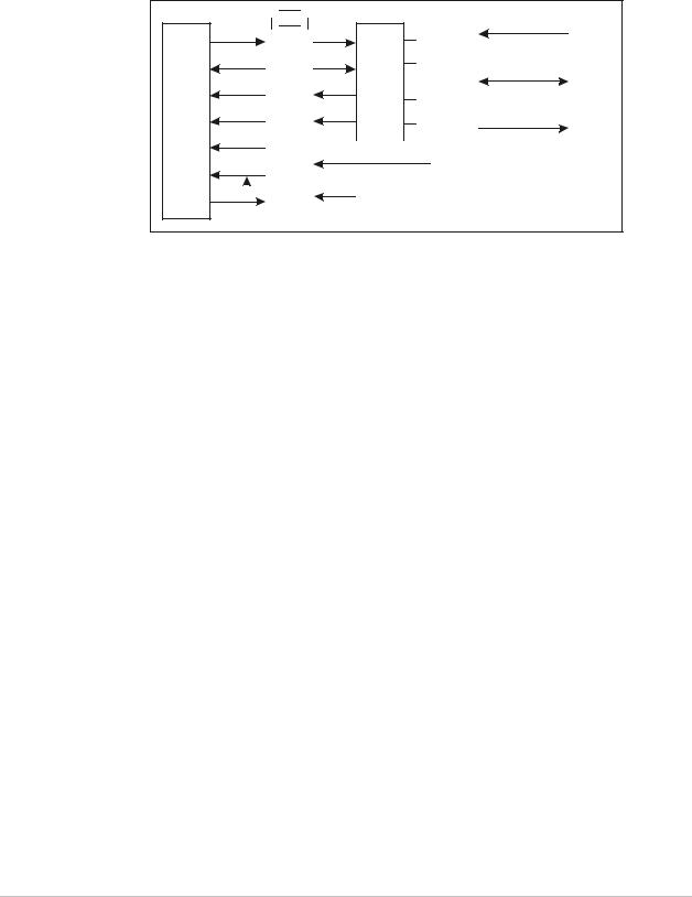
1.3 Functional Description
Functional Block Diagram
Figure 1-3 shows the functional block diagram of RIC-E1.
Interfaces Interchangable
 X
X 
Txd |
|
|
Transformers |
Rxd |
|
|
|
|
|
|
|
Txclk |
|
|
|
Rxclk |
LIU |
|
|
|
|
||
Loss |
|
|
|
|
|
|
|
Tst |
|
|
|
Ana |
|
|
Clock |
|
|
|
Gen. |
|
|
|
|
|
|
|
Unbalanced |
|
|
|
|
BNC |
|
|
|
|
|
|
|
Select |
|
Balanced |
|
|
|
|
||
|
|
RJ - 45 |
||
|
IMP |
|
|
|
|
|
|
|
|
|
|
|
Unbalanced |
|
|
|
|
BNC |
|
|
|
|
|
|
|
|
|
|
|
Tx & Rx Code |
|
|
||
|
AMI |
|
|
|
|
HDB3 |
|
|
P.S. |
|
|
|
|
|
|
|
|
|
|
Figure 1-3. RIC-E1 Block Diagram
Timing Reference
RIC-E1 supports three clock modes:
•Internal, derived from its internal oscillator
•External, supplied by the attached DTE
•Receive, recovered from the received line signal.
Diagnostics
RIC-E1 supports a V.54 (loop 3) local loopback activated by the internal jumper of the standalone RIC-E1 unit, front panel pushbutton of the RIC-E1/R card or via corresponding pin of the DTE interface connector (not available for X.21 and Ethernet interfaces). For more information, refer to Chapter 4.
Functional Description |
1-3 |
Order from: Cutter Networks |
Ph:727-398-5252/Fax:727-397-9610 |
www.bestdatasource.com |

Chapter 1 Introduction RIC-E1 Installation and Operation Manual
1.4 Technical Specifications
Link Interface |
Coding |
HDB3 or AMI |
||
|
|
Framing |
Unframed |
|
|
|
Bit Rate |
2.048 Mbps |
|
|
|
Impedance |
120Ω, balanced |
|
|
|
|
75Ω, unbalanced |
|
|
|
RCV Signal Level |
0 to -10 dB |
|
|
|
XMT Signal Level |
3V (±10%), balanced |
|
|
|
|
2.37V (±10%), unbalanced |
|
|
|
Connectors |
RJ-45, 8-pin, balanced |
|
|
|
|
Two BNC coaxial, unbalanced |
|
|
|
Return Loss |
Better than 15 dB |
|
DTE Interface |
Type |
• |
V.35: 34-pin, female |
|
|
|
|
• X.21: 15-pin, D-type female |
|
|
|
|
• V.36: 37-pin, D-type female, via adapter |
|
|
|
|
|
cable |
|
|
|
• RS-530: 25-pin, D-type female |
|
|
|
|
• IR-ETH: RJ-45 or BNC |
|
|
|
|
• IR-ETH/V: RJ-45 |
|
|
|
|
• |
IR-IP: RJ-45 |
|
|
Control Signals |
V.35, X.21, RS-530: |
|
|
|
|
• |
CTS follows RTS |
|
|
|
• DCD follows E1 state |
|
|
|
|
V.35, RS-530: |
|
|
|
|
• DSR is constantly ON |
|
Timing |
|
|
Derived from three alternative sources: |
|
|
|
|
• |
Internal oscillator |
|
|
|
• External, from the attached DTE |
|
|
|
|
• Receive, derived from the received signal |
|
Indicators |
PWR (green) |
On – RIC-E1 is powered |
||
|
|
TXD (yellow) |
On – Data is being transmitted to the link |
|
|
|
RXD (yellow) |
On – Data is being received from the link |
|
|
|
LOS (red) |
On – No E1 data is received from the link |
|
|
|
TST (red) |
On – The local loopback is active |
|
|
|
|
||
|
Note |
For description of the IR-ETH, IR-ETH/V and IR-IP interface modules, refer to |
||
|
Appendix B, Appendix C, and Appendix D, respectively. |
|||
|
|
|||
|
|
|
|
|
1-4 |
Technical Specifications |
|
|
|
Order from: Cutter Networks |
Ph:727-398-5252/Fax:727-397-9610 |
www.bestdatasource.com |

RIC-E1 Installation and Operation Manual |
|
|
Chapter 1 Introduction |
|
|
|
|
||
Diagnostics |
|
Complies with ITU V.54 (loop 3) |
||
|
Local Loopback |
Activated by: |
||
|
|
• Internal jumper (RIC-E1) |
||
|
|
• Front panel pushbutton (RIC-E1/R) |
||
|
|
• DTE circuit 141 for V.35, RS-530 and V.36 |
||
Power |
AC Source |
100 to 240 VAC (± 10%), 50 or 60 Hz |
||
|
DC Source |
• -48 VDC (-36 to -72 VDC) |
||
|
|
• 24 VDC (18 to 36 VDC) |
||
|
Power Consumption |
• |
Standalone: 3W, max |
|
|
|
• |
RIC-E1/R: 5.2W |
|
|
Fuses |
Standalone RIC-E1: 250 mA 250V slowblow |
||
|
|
RIC-E1/R: 500 mA 250V slowblow |
||
Physical |
RIC-E1 |
|
|
|
|
Height |
39.5 mm / 1.5 in |
||
|
Width |
190 mm / 7.4 in |
||
|
Depth |
160 mm / 6.2 in |
||
|
Weight |
|
0.6 kg |
/ 1.3 lb |
Environment |
RIC-E1/R |
Fits one slot in the ASM-MN-214 card cage |
||
|
0–50 C (32–122 F) |
|||
|
Temperature |
|
° |
° |
|
Humidity |
Up to 90%, non-condensing |
||
Technical Specifications |
1-5 |
Order from: Cutter Networks |
Ph:727-398-5252/Fax:727-397-9610 |
www.bestdatasource.com |

Chapter 1 Introduction |
RIC-E1 Installation and Operation Manual |
|
|
1-6 |
Technical Specifications |
Order from: Cutter Networks |
Ph:727-398-5252/Fax:727-397-9610 |
www.bestdatasource.com |
Chapter 2
Installation and Setup
This chapter explains how to configure and install RIC-E1.
After the installation is complete, refer to Chapter 3 for information about operating RIC-E1.
Refer to Chapter 4 for troubleshooting and diagnostics information.
2.1 Site Requirements and Prerequisites
AC-powered RIC-E1 units should be installed within 1.5m (5 ft) of an easily-accessible grounded AC outlet capable of furnishing the required supply voltage, in the range of 100 to 240 VAC.
DC-powered RIC-E1 units require a -48 or 24 VDC power source, which must be adequately isolated from the mains supply. In order to prevent a fire hazard, a suitable fuse must be installed in the live DC line.
Allow at least 90 cm (36 in) of frontal clearance for operator access and at least 10 cm (4 in) clearance at the rear of the unit for interface cable connections.
The ambient operating temperature of RIC-E1 should be 0 to 50°C (32 to 122°F), at a relative humidity of up to 90%, non-condensing.
2.2 Package Contents
The RIC-E1 package includes the following items:
•RIC-E1 unit
•The AC power cord or DC power supply connector kit
•Ethernet over SDH/SONET and Converters CD
•Jumper plug for JP9 jumper
•CBL-530/449 adapter cable for units ordered with V.36 interface
•RM-29 rack installation kit (if ordered).
Package Contents |
2-1 |
Order from: Cutter Networks |
Ph:727-398-5252/Fax:727-397-9610 |
www.bestdatasource.com |

Chapter 2 Installation and Setup |
RIC-E1 Installation and Operation Manual |
|
|
|
|
|
|
|
|
|
|
2.3 Configuring RIC-E1
This section provides information on the functions and locations of RIC-E1 internal jumpers. Use this information to select the correct setting for your particular application.
To install RIC-E1:
1.Determine the required configuration, according to your application, and set the internal jumpers accordingly. For more information, refer to Setting the Jumpers.
2.Connect the DTE and G.703 link interfaces, as explained in Connecting the Interfaces.
3.Connect the power to the unit. For more information, refer to Connecting the Power.
Setting the Jumpers
This section explains how to set the internal jumpers according to your requirements. Figure 2-1 shows the RIC-E1 jumper locations.
Avoid adjusting, maintaining or repairing RIC-E1 while it is connected to the power source.
 Adjusting, maintaining and repairing RIC-E1, while connected to power supply Warning should only be done by a skilled technician aware of the hazards involved.
Capacitors inside the instrument may still be charged even after the instrument has been disconnected from its source of supply.
To set the jumpers:
1.Disconnect the power cable from the mains outlet.
2.Slide the blue side panel forward to detach it from the case.
3.Unscrew the two screws located on the bottom panel at the rear end of the unit.
4.Separate the two halves of the RIC-E1 case by lifting the top cover at the end of the unit and sliding it forward.
5.Adjust the RIC-E1 internal jumpers, as described in Table 2-1. Figure 2-1 shows the jumper locations.
6.Reinstall the cover and tighten the screws.
2-2 |
Configuring RIC-E1 |
Order from: Cutter Networks |
Ph:727-398-5252/Fax:727-397-9610 |
www.bestdatasource.com |

RIC-E1 Installation and Operation Manual |
|
Chapter 2 Installation and Setup |
||||
|
|
|
|
|
|
|
|
|
|
|
|
|
|
|
|
|
|
|
|
|
|
|
|
|
|
|
|
|
|
|
|
|
|
|
JP1 JP2 JP3 JP4 |
 BAL
BAL
 BNC
BNC
BAL |
JP6 |
|
BNC |
||
|
||
RCV |
J4 |
|
|
||
EXT |
|
|
INT |
|
|
TX & RX CODE |
||
AMI |
JP9 |
|
|
||
HDB3 |
||
LOC |
JP11 |
DTE |
ANA LOOP
|
Figure 2-1. RIC-E1 Jumper Locations |
|
|
|
Table 2-1. |
RIC-E1 Jumper Settings |
|
|
|
|
|
Jumper |
Description |
Values |
Default Setting |
|
|
|
|
JP1, JP2, JP3, JP4, |
Select the E1 interface type |
BAL – Balanced interface |
BAL |
JP6 |
|
(RJ-45 connector) |
|
|
|
BNC – Unbalanced interface (BNC |
|
|
|
coax connectors) |
|
|
|
|
|
TX & RX CODE, |
Selects the transmit and |
AMI – Jumper plug is installed |
|
JP9 |
receive coding |
HDB3 – Jumper plug is not installed |
HDB3 |
|
|
||
|
|
|
|
TIMING, J4 |
Selects the clock reference |
RCV (pin 4) – Receive clock |
RCV |
|
|
EXT (pin 5) – External clock |
|
|
|
INT (pin 6) – Internal clock |
|
Note: Units with the IR-ETH, IR-ETH/V and IR-IP interface modules support only receive and internal clocks.
ANA LOOP, JP11 Controls the local analog |
LOC – Activates the local analog |
|
loopback activation |
loopback |
|
|
DTE – Allows the activation of the |
DTE |
|
local analog loopback via DTE |
|
|
|
|
Configuring RIC-E1 |
2-3 |
Order from: Cutter Networks |
Ph:727-398-5252/Fax:727-397-9610 |
www.bestdatasource.com |
Chapter 2 Installation and Setup |
RIC-E1 Installation and Operation Manual |
|
|
Selecting the Impedance
When RIC-E1 uses the balanced interface:
•Terminate the impedance of G.703 link to 120Ω.
•Use only the RJ-45 connector to transmit full duplex data to the G.703 network over UTP or STP cable.
When RIC-E1 uses the unbalanced interface:
•Terminate the impedance of G.703 link to 75Ω.
•Use only the coaxial BNC connectors to transmit to the G.703 network via two coaxial cables.
Closing the RIC-E1 Case
After completing the internal settings, close the unit case.
To close the RIC-E1 case:
1.Position the lower half of the RIC-E1 case on the flat surface.
2.Install the top cover making sure the top cover guides enter the corresponding recesses at the end of the unit.
3.Secure the two screws located at the end of the unit.
4.Fit the inside tabs of the blue side panel into the unit case grooves, and slide the side panel until snaps into place.
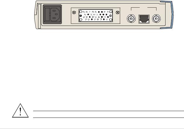
Connecting the Interfaces
Figure 2-2 and shows the rear panel of the AC-powered RIC-E1 unit.
V.35 |
LINK |
|
|
TX |
RX |
Figure 2-2. RIC-E1 Rear Panel
Connecting the E1 Line
RIC-E1 link interface terminates in balanced and unbalanced connectors, marked LINK.
To connect the balanced interface:
•Use RJ-45 male connector and connect it to the RIC-E1 RJ-45 port. Appendix A lists the balanced connector pin assignment.
To connect the unbalanced interface:
1.Connect the receive line to the back panel connector designated TX.
2.Connect the transmit line to the back panel connector designated RX.
Do not connect both balanced and unbalanced connectors.
Warning
2-4 |
Configuring RIC-E1 |
Order from: Cutter Networks |
Ph:727-398-5252/Fax:727-397-9610 |
www.bestdatasource.com |

RIC-E1 Installation and Operation Manual |
Chapter 2 Installation and Setup |
|
|
Connecting the DTE
RIC-E1 supports various types of data channel interfaces. Equipment with V.35, X.21, RS-530 and Ethernet interfaces can be connected directly to the RIC-E1 DTE port. The RIC-E1 V.36 interface is provided via an adapter cable converting between 25-pin RS-530 connector and 37-pin V.36 connector.
Connector pin allocations and cable wiring data appear in Appendix A. For the detailed description of the IR-ETH, IR-ETH/V, and IR-IP Ethernet interface modules, refer to Appendix B, Appendix C, and Appendix D, respectively.
Connecting the Power
Refer to the appropriate section below depending on the RIC-E1 version – AC or DC.
Connecting the AC Power
AC power should be supplied to the RIC-E1 unit through the 1.5m (5 ft) standard power cable terminated with a standard 3-prong plug. The cable is provided with the unit.
Before connecting power to the unit, verify that the socket outlet is provided with a protective ground contact. If you are using an extension cord (power
cable) make sure it is grounded as well
Warning Interrupting the protective (grounding) conductor (inside or outside the unit), or disconnecting the protective ground terminal can make this unit dangerous.
Make sure that only fuses of the required rating (0.250A, 250V) are used for replacement. Do not use repaired fuses or short-circuit the fuse holder. Always disconnect the mains cable before removing or replacing the fuse. If there is a chance that the fuse protection has been damaged, make the unit inoperative.
To connect AC power to RIC-E1:
1.Connect the power cable to the power connector on the RIC-E1 rear panel.
2.Plug the RIC-E1 power cable to the mains outlet.
RIC-E1 turns on automatically upon connection to the mains.
Connecting the DC Power
To connect DC power:
•Refer to the DC power supply connection supplement.
Configuring RIC-E1 |
2-5 |
Order from: Cutter Networks |
Ph:727-398-5252/Fax:727-397-9610 |
www.bestdatasource.com |

Chapter 2 Installation and Setup |
RIC-E1 Installation and Operation Manual |
|
|
2-6 |
Configuring RIC-E1 |
Order from: Cutter Networks |
Ph:727-398-5252/Fax:727-397-9610 |
www.bestdatasource.com |
Chapter 3
Operation
This chapter describes how to operate RIC-E1. Installation procedures explained in Chapter 2 must be completed and checked before attempting to operate RIC-E1.
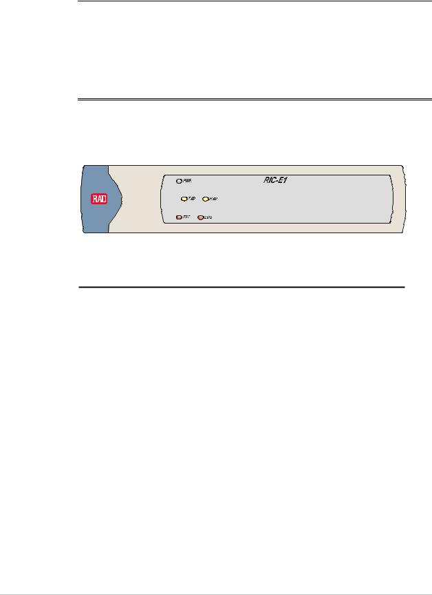
3.1 Front Panel Indicators
Figure 3-1 shows the RIC-E1 front panel. The front panel indicators are described in Table 3-1.
Figure 3-1. RIC-E1 Front Panel
Table 3-1. RIC-E1 Front Panel LED Indicators
Designation |
Color |
Function |
|
|
|
PWR |
Green |
ON – RIC-E1 is powered up |
|
|
|
TXD |
Yellow |
ON – Data is being transmitted to the link |
|
|
|
RXD |
Yellow |
ON – Data is being received from the link |
|
|
|
LOS |
Red |
ON – No E1 data is received from the link |
|
|
|
TST |
Red |
ON – The local loopback is active |
|
|
|
Front Panel Indicators |
3-1 |
Order from: Cutter Networks |
Ph:727-398-5252/Fax:727-397-9610 |
www.bestdatasource.com |

Chapter 3 Operation |
RIC-E1 Installation and Operation Manual |
|
|
|
|
|
|
|
|
|
|
3.2 Operating Instructions
Turning On
RIC-E1 starts operating as soon as AC or DC power is connected. Always connect the power cable to the RIC-E1 power connector first and then to the mains outlet.
The PWR LED lights when power is connected.
Operating RIC-E1
RIC-E1 operates entirely unattended except when performing system tests.
Turning Off
To turn RIC-E1 off, disconnect the power cable from the mains outlet.
3-2 |
Operating Instructions |
Order from: Cutter Networks |
Ph:727-398-5252/Fax:727-397-9610 |
www.bestdatasource.com |
Chapter 4
Troubleshooting and
Diagnostics
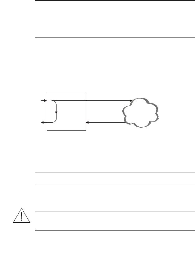
4.1 Performing Local Analog Loopback
RIC-E1 supports activation of a V.54 diagnostic (loop 3) local loopback.
This loopback checks the communication and connection between RIC-E1 and the attached DTE, as shown in Figure 4-1. When RIC-E1 performs a local loopback, the data received from the local transmitter is both transmitted on the line and looped back to the local receiver at the digital level. This checks the operation of all local digital circuitry.
DTE |
Line |
Tx |
Tx |
|
|
|
G.703 |
|
Network |
Rx |
Rx |
|
RIC-E1
Figure 4-1. RIC-E1 Local Loopback
Activating Local Analog Loopback
You can activate the local analog loopback via DTE interface circuit 141 (for V.35, RS-530 and V.36 interfaces only).
Note When activating the local analog loopback via interface of the DTE connected to the RIC-E1/R card, make sure to set the ALB DTE jumper (JP4) to EN.
Alternatively, you can initiate the loopback via internal jumper of the standalone RIC-E1 or by pressing the ANA pushbutton on the RIC-E1/R panel.
Do not touch any components other than ANA LOOP (JP11) jumper plug while activating the local loopback from the standalone RIC-E1, in order to avoid
Warning electrical shock.
Performing Local Analog Loopback |
4-1 |
Order from: Cutter Networks |
Ph:727-398-5252/Fax:727-397-9610 |
www.bestdatasource.com |

Chapter 4 Troubleshooting and Diagnostics |
RIC-E1 Installation and Operation Manual |
|
|
To activate the local analog loopback from the standalone RIC-E1:
1.Open the RIC-E1 case, as described in Chapter 2.
2.Set the JP11 jumper to LOC.
The analog loopback is activated and the TST indicator on the front panel turns on.
To activate the local analog loopback from RIC-E1/R:
•Press the ANA pushbutton on the RIC-E1/R front panel.
Make sure that the PNL SW jumper (JP5) on the RIC-E1/R board is set to EN.
The TST indicator on the front panel turns on.
Deactivating Local Analog Loopback
To deactivate the local analog loopback from the DTE:
•Lower the circuit 141 pins of the DTE interface.
To deactivate the local analog loopback from the standalone RIC-E1:
•Set the RIC-E1 JP11 jumper to DTE.
The TST indicator on the front panel turns off.
To deactivate the local analog loopback from the standalone RIC-E1/R:
•Press the RIC-E1/R ANA pushbutton again to return it to the previous position.
4.2 Troubleshooting
Table 4-1 contains troubleshooting information to help you identify and correct problems.
Table 4-1. RIC-E1 Troubleshooting
|
Trouble Symptoms |
Probable Cause |
Corrective Measures |
|
||
|
|
|
|
|
|
|
|
All front panel indicators |
1. |
No power |
Check that both ends of the power cable |
||
|
are OFF |
|
|
|
are properly connected. |
|
|
|
|
|
|
|
|
|
|
|
2. |
Blown fuse |
Disconnect power cable from both ends |
|
|
|
|
|
|
and replace the fuse with another fuse of |
|
|
|
|
|
|
proper rating. |
|
|
|
|
|
|
|
|
|
LOS indicator is ON |
1. |
Receive line fuses are blown |
Disconnect power cable from both ends |
||
|
|
|
|
|
and replace the fuses with new fuses of |
|
|
|
|
|
|
proper rating. |
|
|
|
|
|
|
|
|
|
|
|
2. |
Line cables are not properly |
Check and adjust both ends of the line |
|
|
|
|
|
connected |
cables. |
|
|
|
|
|
|
|
|
|
|
|
3. |
Unbalanced BNC connectors |
Switch the two BNC connectors. |
|
|
|
|
|
are reversed |
|
|
|
|
|
|
|
|
|
|
|
|
4. |
The transformer is damaged |
Replace RIC-E1. |
|
|
|
|
|
|
|
|
|
|
|
|
|
|
|
4-2 |
Troubleshooting |
|
|
|
|
|
Order from: Cutter Networks |
Ph:727-398-5252/Fax:727-397-9610 |
www.bestdatasource.com |
 Loading...