


 Loading...
LRS-24
12-slot Link Access Rack with SNMP
Version 3.00
Installation and Operation Manual
Notice
This manual contains information that is proprietary to RAD Data Communications. No part of this publication may be reproduced in any form whatsoever without prior written approval by RAD Data Communications.
No representation or warranties for fitness for any purpose other than what is specifically mentioned in this manual is made either by RAD Data Communications or its agents.
For further information contact RAD Data Communications at the address below or contact your local distributor.
RAD Data Communications |
RAD Data Communications |
RAD Data Communications |
Headquarters |
US East |
US West |
12 Hanechoshet Street |
900 Corporate Drive |
3631 South Harbor Boulevard |
Tel Aviv 69710 Israel |
Mahwah, NJ 07430 USA |
Suite 250 |
Tel: 972-3-6458181 |
Tel: (201) 529-1100 |
Santa Ana, CA 92704 |
Fax: 972-3-6498250 |
Fax: (201) 529-5777 |
Tel: (714) 850-0555 |
E-mail: rad@rad.co.il |
E-mail: market@radusa.com |
Fax: (714) 850-1555 |
|
|
|
© 2000 RAD Data Communications |
Publication No. 695-211-08/00 |
Order from: Cutter Networks |
Ph:727-398-5252/Fax:727-397-9610 |
www.bestdatasource.com |
Order from: Cutter Networks |
Ph:727-398-5252/Fax:727-397-9610 |
www.bestdatasource.com |
Warranty
This RAD product is warranted against defects in material and workmanship for a period of one year from date of shipment. During the warranty period, RAD will, at its option, either repair or replace products which prove to be defective. For warranty service or repair, this product must be returned to a service facility designated by RAD. Buyer shall prepay shipping charges to RAD and RAD shall pay shipping charges to return the product to Buyer. However, Buyer shall pay all shipping charges, duties and taxes for products returned to RAD from another country.
Limitation of Warranty
The foregoing warranty shall not apply to defects resulting from improper or inadequate maintenance by Buyer, Buyer-supplied firmware or interfacing, unauthorized modification or misuse, operation outside of the environmental specifications for the product, or improper site preparation or maintenance.
Exclusive Remedies
The remedies provided herein are the Buyer’s sole and exclusive remedies. RAD shall not be liable for any direct, indirect special, incidental, or consequential damages, whether based on contract, tort, or any legal theory.
Order from: Cutter Networks |
Ph:727-398-5252/Fax:727-397-9610 |
www.bestdatasource.com |

Safety Warnings
SEE INSTALLATION INSTRUCTIONS BEFORE CONNECTING TO THE SUPPLY!
The exclamation point within a triangle is intended to warn the operator or service personnel of operation and maintenance factors relating to the product and its operating environment which could pose a safety hazard.
Always observe standard safety precautions during installation, operation and maintenance of this product. Only a qualified and authorized service personnel should carry out adjustment, maintenance or repairs to this instrument. No adjustment, maintenance or repairs should be performed by either the operator or the user.
Telecommunication Safety
1.The unit should be installed within 1.5m (5 feet) of a grounded, easily accessible AC outlet, or in an adequately earthed rack mount. If the protective earth connection is not guaranteed by the mains supply, the unit must be externally connected to a reliable protective earth. DC powered units must be connected only to power sources which conform to the relevant safety standard.
2.In order to guarantee an uninterrupted flow of air stream, leave at least 15 mm spacing above and below the top and bottom sides of the unit. The recommended maximum temperature of the surrounding area is 40°C.
3.Vacant slots must always be covered with blank covers. This is necessary in order to guarantee a definite cooling stream of air and to prevent unintentional and unauthorized access inside the equipment.
4.The safety status of the ports on the LRS-24 is declared according to EN 41003 and is detailed in the table below. Interconnection of these ports with other apparatus should be made so that the equipment continues to comply with the requirements of EN 60950 connection of SELV and TNV circuits to other circuits after such a connection is made.
Ports |
Safety Status |
|
|
|
|
V.24, V.35, V.36, X.21, RS-530, |
SELV |
Circuit operating with Safety Extra-Low Voltage |
Unbalanced E1, E&M |
|
|
|
|
|
Baseband modems, ISDN, |
TNV-1 |
Circuit whose normal operating voltage is within |
Balanced E1, T1, HDSL |
|
the limits of SELV, on which overvoltages from |
|
|
Telecommunications Networks are possible. |
FXS |
TNV-2 |
Circuit whose normal operating voltage exceeds |
|
|
the limits of SELV, on which overvoltages from |
|
|
Telecommunications Networks are not possible. |
|
|
|
FXO, Ports with remote power |
TNV-3 |
Circuit whose normal operating voltage exceeds |
feeding (phantom) |
|
the limits of SELV, on which overvoltages from |
|
|
Telecommunications Networks are possible. |
Order from: Cutter Networks |
Ph:727-398-5252/Fax:727-397-9610 |
www.bestdatasource.com |
Additional conditions concerning the safety of connection to telecommunication networks:
•The unit must be earthed prior to connection to telecommunication networks.
•The signal ground of the SELV circuits is connected at the factory to the protective earth. Interrupting this connection may invalidate the safety of the connection to unprotected telecommunication networks in certain locations where permanent excessive voltages are present on the lines.
•In order to comply with the requirements set out in EN 60950 for TNV-3 circuits, the maximum phantom supply voltage must not exceed 120 VDC. The remote power feeding supply must be floating and must comply with the requirements for TNV-3 circuits.
•DC powered units must be powered from EN 60950 or UL-1950 approved power source. In order to avoid a fire hazard, a suitable fuse or circuit breaker must be installed on the non-earthed DC line.
Regulatory Information
FCC-15 User Information
This equipment has been tested and found to comply with the limits of the Class A digital device, pursuant to Part 15 of the FCC rules. These limits are designed to provide reasonable protection against harmful interference when the equipment is operated in a commercial environment. This equipment generates, uses and can radiate radio frequency energy and, if not installed and used in accordance with the instruction manual, may cause harmful interference to the radio communications. Operation of this equipment in a residential area is likely to cause harmful interference in which case the user will be required to correct the interference at his own expense.
Warning per EN 55022
This is a Class A product. In a domestic environment, this product may cause radio interference, in which case the user may be required to take adequate measures.
LRS-PS-FEED Output Voltage
The output voltage of the LRS-PS-FEED exceeds the limits of TNV-3 circuits. In the event of uncertainty about the regulatory status of connecting such voltages to leased lines provided by certain service providers, consult with a safety engineer.
Order from: Cutter Networks |
Ph:727-398-5252/Fax:727-397-9610 |
www.bestdatasource.com |

Declaration of Conformity
Manufacturer’s Name: |
RAD Data Communications Ltd. |
Manufacturer’s Address: |
12 Hanechoshet St. |
|
Tel Aviv 69710 |
|
Israel |
declares that the product: |
|
Product Name: |
LRS-24 |
Conforms to the following standard(s) or other normative document(s):
EMC: |
EN 55022 (1994) |
Limits and methods of measurement of radio disturbance |
|
|
characteristics of information technology equipment. |
|
EN 50082-1 (1992) Electromagnetic compatibility - Generic immunity |
|
|
|
standards for residential, commercial and light industry. |
Safety: |
EN 60950/A4 |
Safety of information technology equipment, including |
|
|
electrical business equipment. |
Supplementary Information:
The product herewith complies with the requirements of the EMC Directive 89/336/EEC and the Low Voltage Directive 73/23/EEC. The product was tested in a typical configuration.
Tel Aviv, March 19th, 2000
Haim Karshen
VP Quality
European Contact: Rad Data Communications GmbH, Berner Strasse 77, 60437, Frankfurt am Main, Germany
Order from: Cutter Networks |
Ph:727-398-5252/Fax:727-397-9610 |
www.bestdatasource.com |

Quick Start Guide
If you are familiar with LRS-24, use this guide to prepare it for operation. Choose the section appropriate to the version of LRS-24 you are using.
1.LRS-24 with CM-1 Module
This section contains the startup instructions for LRS-24 with the CM-1 module.
Power-On
To turn the power on:
1.Set the ON/OFF switches on the panels of the LRSI-PSP** modules to ON.
2.Supply the DC power, as applicable.
To supply external phantom feed voltages:
1.Turn on LRS-24.
2.Turn on the source (for example, LRS-PS-FEED).
Normal Indications
•PS Module(s): All the indicators on the panel(s) of the PS module(s) must light in green to indicate proper operation.
•CM-1 Module: The POWER indicator of the module must light. The TD and RD indicators may flash (or may light steadily) when a management session is in progress.
LRS-24 with CM-2 Module |
1 |
Order from: Cutter Networks |
Ph:727-398-5252/Fax:727-397-9610 |
www.bestdatasource.com |

Quick Start Guide |
LRS-24 Installation and Operation Manual |
|
|
|
|
|
|
2.LRS-24 with CM-2 Module
This section contains the startup instructions for LRS-24 with the CM-2 module.
Power-On
To turn the power on:
1.Set the ON/OFF switches on the panels of the LRSI-PSP** modules to ON.
2.Supply the DC power, as applicable.
To supply external phantom feed voltages:
1.Turn on LRS-24.
2.Turn on the source (for example, LRS-PS-FEED).
Normal Indications
•PS Module(s): All the indicators on the panel(s) of the PS module(s) must light in green to indicate proper operation.
•CM-2 Module: The POWER indicator of the module must light. The TD and RD indicators may flash (or light steadily) when a management session is in progress.
Normally, the STAT/ADD display shows the two least significant digits of the management number assigned to LRS-24. For normal startup, a rotating red circle is displayed. However, if a problem is detected during the power-up self-test, you will see a flashing error code (E1 through E9).
Preliminary Configuration
Perform preliminary configuration on the LRS-24 hub (see Chapter 4).
2 |
LRS-24 with CM-2 Module |
Order from: Cutter Networks |
Ph:727-398-5252/Fax:727-397-9610 |
www.bestdatasource.com |

Contents
Chapter 1. Introduction |
|
|
1.1 |
Overview .......................................................................................................... |
1-1 |
|
General ................................................................................................................... |
1-1 |
|
Versions................................................................................................................... |
1-3 |
|
Application .............................................................................................................. |
1-3 |
|
Features................................................................................................................... |
1-4 |
1.2 |
Physical Description .......................................................................................... |
1-6 |
|
Chassis Description.................................................................................................. |
1-6 |
|
LRS-24 Module Slots.............................................................................................. |
1-10 |
1.3 |
Functional Description .................................................................................... |
1-11 |
|
Power Supply (PS) Modules ................................................................................... |
1-11 |
|
Common Logic Modules........................................................................................ |
1-12 |
|
Management ......................................................................................................... |
1-13 |
|
I/O (User) Modules ................................................................................................ |
1-14 |
1.4 |
Technical Specifications .................................................................................. |
1-14 |
Chapter 2. Installation and Setup |
|
|
2.1 |
Introduction ...................................................................................................... |
2-1 |
|
Mechanical Data...................................................................................................... |
2-1 |
2.2 |
Site Requirements and Prerequisites.................................................................. |
2-4 |
|
AC Power ................................................................................................................ |
2-4 |
|
DC Power................................................................................................................ |
2-4 |
|
Grounding ............................................................................................................... |
2-4 |
|
Interface Module Handling Precautions.................................................................... |
2-4 |
|
Module Handling Precautions .................................................................................. |
2-5 |
|
Front Clearance ....................................................................................................... |
2-5 |
|
Ambient Requirements ............................................................................................ |
2-5 |
|
Cooling.................................................................................................................... |
2-5 |
2.3 |
Unpacking the Chassis ...................................................................................... |
2-5 |
2.4 |
Installation and Setup........................................................................................ |
2-6 |
|
PS Modules ............................................................................................................. |
2-6 |
|
CM-1 Module.......................................................................................................... |
2-8 |
|
CM-2 Module........................................................................................................ |
2-12 |
2.5 |
Interfaces and Connections ............................................................................. |
2-15 |
|
PS Interface Modules ............................................................................................. |
2-16 |
|
LRSI-F-CM1........................................................................................................... |
2-17 |
|
LRSI-F-1-CM2 / LRSI-B-1-CM2 Interface Modules with 10BaseT............................. |
2-18 |
|
LRSI-F-2-CM2 Interface Module with 10Base2 ....................................................... |
2-21 |
|
LRS-24 Enclosure................................................................................................... |
2-24 |
2.6 |
Initial Operation and Basic Checks.................................................................. |
2-27 |
|
LRS-24 with CM-1 Module .................................................................................... |
2-27 |
|
LRS-24 with CM-2 Module .................................................................................... |
2-28 |
LRS-24 Installation and Operation |
i |
Order from: Cutter Networks |
Ph:727-398-5252/Fax:727-397-9610 |
www.bestdatasource.com |

Table of Contents
Chapter 3. Management via the CM-1 Module |
|
|
3.1 |
Introduction ...................................................................................................... |
3-1 |
|
CM-1 Functions ....................................................................................................... |
3-1 |
|
Management Capabilities......................................................................................... |
3-1 |
3.2 |
Hardware Requirements ................................................................................... |
3-2 |
|
Terminal Characteristics ........................................................................................... |
3-2 |
|
Management RS-232 Port Interface Characteristics................................................... |
3-2 |
|
Connecting the Terminal.......................................................................................... |
3-2 |
3.3 |
Operating the CM-1 Supervision Terminal ........................................................ |
3-4 |
|
General ................................................................................................................... |
3-4 |
|
Configuring the Terminal ......................................................................................... |
3-4 |
|
Performing Preliminary Configuration....................................................................... |
3-5 |
|
Configuring Individual Modules................................................................................ |
3-5 |
Chapter 4. Management via the CM-2 Module |
|
|
4.1 |
Introduction ...................................................................................................... |
4-1 |
|
CM-2 Module Capabilities ....................................................................................... |
4-1 |
|
CM-2 Functions ....................................................................................................... |
4-2 |
|
Handling of Management Communication............................................................... |
4-3 |
|
Management Priorities ............................................................................................. |
4-4 |
|
Preliminary Configuration Activities.......................................................................... |
4-4 |
|
Initializing CM-2 ...................................................................................................... |
4-5 |
4.2 |
Hardware Requirements ................................................................................... |
4-6 |
|
Terminal Characteristics ........................................................................................... |
4-6 |
|
RS-232 Supervisory Port Interface Characteristics ..................................................... |
4-7 |
|
Terminal Connection Methods................................................................................. |
4-7 |
|
Connection of Management Station ........................................................................ |
4-7 |
4.3 |
CM-2 Supervision Terminal Language ............................................................. |
4-11 |
|
General ................................................................................................................. |
4-11 |
|
Index of Commands .............................................................................................. |
4-12 |
4.4 |
Supervision Terminal Operating Instructions.................................................... |
4-13 |
|
General ................................................................................................................. |
4-13 |
|
Configuring the Terminal ....................................................................................... |
4-13 |
|
Changing the Password .......................................................................................... |
4-14 |
|
Preliminary Configuration ...................................................................................... |
4-14 |
|
Configuring Individual Modules.............................................................................. |
4-14 |
|
Configuration by SNMP Network Management Stations ......................................... |
4-15 |
|
Transferring Control to the Supervision Terminal .................................................... |
4-15 |
Chapter 5. Troubleshooting and Diagnostics |
|
|
5.1 |
Alarms............................................................................................................... |
5-1 |
5.2 |
Diagnostic Tests ................................................................................................ |
5-1 |
5.3 |
Troubleshooting ................................................................................................ |
5-1 |
5.4 |
Error Messages .................................................................................................. |
5-2 |
ii |
LRS-24 Installation and Operation |
Order from: Cutter Networks |
Ph:727-398-5252/Fax:727-397-9610 |
www.bestdatasource.com |
Table of Contents
Appendix A. Connector Wiring
Appendix B. LRS-PS-FEED Power Supply
Appendix C. SNMP Management
Appendix D. CM-2 Management Commands
List of Figures
1-1. |
Backbone Data Distribution up to Customer’s Premises............................................. |
1-3 |
1-2. |
Management of Local and Remote Distribution Nodes .............................................. |
1-4 |
1-3. |
LRS-24B 3-D View .................................................................................................... |
1-7 |
1-4. |
LRS-24B Enclosure .................................................................................................... |
1-8 |
1-5. |
LRS-24F 3-D View..................................................................................................... |
1-9 |
1-6. |
LRS-24F Enclosure................................................................................................... |
1-10 |
1-7. |
LRS-24F Enclosure, Typical Front View.................................................................... |
1-11 |
1-8. |
Basic Management Configuration for LRS-24 with CM-2 Modules ........................... |
1-14 |
2-1. |
LRS-24F Mechanical Diagram.................................................................................... |
2-2 |
2-2. |
LRS-24B Mechanical Diagram ................................................................................... |
2-3 |
2-3. |
PS Module Panels...................................................................................................... |
2-7 |
2-4. |
Module CM-1 Front Panel......................................................................................... |
2-9 |
2-5. |
Module CM-1, Internal Jumpers .............................................................................. |
2-10 |
2-6. |
Module CM-2 Front Panel....................................................................................... |
2-12 |
2-7. |
Module CM-2, Internal Jumpers .............................................................................. |
2-14 |
2-8. |
LRSI-F-PSP/230/114 and LRSI-F-PS/48 Interface Module Panels .............................. |
2-17 |
2-9. |
Typical LRSI-F-CM1 Interface Module Panel............................................................ |
2-18 |
2-10. |
LRSI-F-1-CM2 / LRSI-B-1-CM2 Interface Module Panel with 10BT ........................ |
2-19 |
2-11. |
Interface Module LRSI-F-1-CM2 with UTP Connector, Internal Jumpers ................ |
2-20 |
2-12. |
LRSI-F-2-CM2 Interface Module Panel with 10B2 ................................................. |
2-22 |
2-13. |
Interface Module LRSI-F-2-CM2 with BNC Connectors, Internal Jumpers .............. |
2-23 |
3-1. |
Typical Direct Connection of Supervision Terminal ................................................... |
3-3 |
3-2. |
Typical Connection of Supervision Terminal Through Modem Link ........................... |
3-4 |
4-1. |
Typical Direct Connection of Supervision Terminal ................................................... |
4-8 |
4-2. |
Typical Connection of Supervision Terminal Through Modem Link ........................... |
4-8 |
4-3. |
Typical Connection of Supervision Terminal Through Slip ......................................... |
4-9 |
4-4. |
Typical Connection to Network Management Station .............................................. |
4-10 |
4-5. |
Password Menu Screen ........................................................................................... |
4-14 |
4-6. |
JP15 Settings............................................................................................................ |
4-14 |
5-1. |
Error Indicators.......................................................................................................... |
5-2 |
LRS-24 Installation and Operation |
iii |
Order from: Cutter Networks |
Ph:727-398-5252/Fax:727-397-9610 |
www.bestdatasource.com |

Table of Contents
List of Tables
2-1. |
PS Modules, Front Panel Indicators............................................................................ |
2-7 |
2-2. |
Module CM-1, Front Panel Components ................................................................... |
2-9 |
2-3. |
Module CM-1 Jumper Settings................................................................................. |
2-11 |
2-4. |
Module CM-2, Front Panel...................................................................................... |
2-13 |
2-5. |
Module CM-2 Jumper Settings................................................................................. |
2-15 |
2-6. |
PS Interface Module Types ...................................................................................... |
2-16 |
2-7. Management 10BT Ethernet LEDs ............................................................................ |
2-19 |
|
2-8. |
LRSI-F-1-CM2 Module Jumper Settings.................................................................... |
2-21 |
2-9. |
LRSI-F-2-CM2 Interface Module Jumper Settings ..................................................... |
2-23 |
2-10. |
CM-2 Module STATION CLK Connector, Pin Allocation........................................ |
2-26 |
2-11. CM-1 Module Management RS-232 Pin Allocation................................................. |
2-27 |
|
4-1. Terminal Command Set Index for CM-2 Module...................................................... |
4-12 |
|
4-2. |
Terminal Command Set Index for CM-2 Module (Cont.) ......................................... |
4-13 |
5-1. |
Front Panel Indicator Displays ................................................................................... |
5-2 |
5-2. |
Error Messages........................................................................................................... |
5-3 |
iv |
LRS-24 Installation and Operation |
Order from: Cutter Networks |
Ph:727-398-5252/Fax:727-397-9610 |
www.bestdatasource.com |

Chapter 1
Introduction
This chapter describes the basic physical and functional features of the LRS-24 modem rack, as well as some typical applications. The following topics are discussed:
•Overview
•Physical Description
•Functional Description
•Technical Specifications.
1.1 Overview
General
LRS-24 is a high-density SNMP managed modem chassis. The chassis has 12 slots that accommodate up to 24 modems. Using modular interface cards, LRS-24 can support xDSL, fiber or baseband modems in the same chassis under a single management application.
Supporting different modem technologies enables a wide range of data-rates, starting from 1.2 kbps in IDSL modems, through 2 Mbps with HDSL/fiber modems, and up to 43 Mbps using fiber modems. This also enables ranges from 4.8 km at
2 Mbps over copper to 100 km over fiber modems.
LRS-24 is available in two different physical hub versions: LRS-24B (ANSI) or
LRS-24F (ETSI).
All cards can be replaced or cables removed during operation, without causing interference to data transmission to/from other cards in the chassis.
Modular data interfaces allow modem connectivity via a wide range of data interfaces. These include: V.24, V.35, X.21, RS-530, V.36, G.703 codirectional, E1, built-in Ethernet bridge, or built-in IP router.
LRS-24 accepts a system clock via the DB-15 connector placed on the CM-2 card.
Overview 1-1
Order from: Cutter Networks |
Ph:727-398-5252/Fax:727-397-9610 |
www.bestdatasource.com |

Chapter 1 Introduction |
LRS-24 Installation and Operation Manual |
|
|
Management/CM-2 functions
LRS-24 is managed by a UNIX-based or PC-based SNMP management system via the Central Management card (CM-2). The software is user-friendly,
GUI-based and runs under PC/Windows (RADview-PC) or HP OpenView (RADview-HPOV) systems. Configuration and monitoring are also provided via TELNET or ASCII terminal.
Network management provides centralized control of all LRS-24 hubs, modem cards and remote modems in the network, including interface configuration, connection setup, alarm and monitoring. A single management station can control up to 64,000 LRS-24 hubs.
Direct 10BaseT Ethernet connection enables real-time management of central and remote sites. Performance information is available in graph and table format for the last 24 hours. This information can be saved in a file for accounting purposes.
If a major alarm occurs, the LRS-24 CM-2 card can dial out through an external dial-up modem to a central management site. This saves a direct connection to remote sites, while providing alerts if critical events occur. In addition alarms can activate dry contacts. The dry contacts are placed on the system clock connector on CM-2.
Two types of modem cards are available on the LRS-24:
•S-Mode: Cards with a built-in SNMP agent
•I-Mode: Cards without an SNMP agent. For these cards CM-2 serves as the SNMP proxy agent. The CM-2 built-in agent complies with SNMP MIB II and supports generic SNMP HPOV applications.
A new software version can be downloaded from a remote site onto the CM-2 via:
•LAN by TFTP protocol
•Terminal by XMODEM.
CM-2 saves up to three software versions.
When the management station includes BootP software, the CM-2 card automatically retrieves the IP address required for management connection. This eliminates the need to configure IP addresses for new hub installations.
LRS-24 can also be managed from an ASCII terminal. It allows all functions of SNMP except for GUI interface. The connection is made via a V.24 supervisory port using SLIP or PPP protocol.
Telnet support enables terminal connection over any IP network.
The CM-2 panel includes an alphanumeric display with two characters used for alerting on fault conditions and for the hub IP address.
1-2 Overview
Order from: Cutter Networks |
Ph:727-398-5252/Fax:727-397-9610 |
www.bestdatasource.com |
LRS-24 Installation and Operation Manual |
Chapter 1 Introduction |
|
|
Power Supplies
LRS-24 operates with single or dual, AC or DC power supplies. Each power supply supports a full LRS-24 hub, including modem cards. Redundant power supply can be replaced during operation, without affecting system performance (hot-swapping).
Cards in the LRS-24 chassis are capable of providing remote power feeding for repeaters and remote standalone modems. To provide remote power feeding order a separate standalone power supply, LRS-PS-FEED.
Versions
Two different physical versions of the LRS-24 hub are available:
•ANSI − card insertion, LEDs and switches are at the front, but cable connections are at the rear of the hub. This compact, 4U high unit complies with the American ANSI standard. Cards can be hot-swapped without removing cables.
•ETSI − card insertion, LEDs, switches and cable connections are at the front. This version is 30 cm high (almost 6U), and complies with European ETSI standard. Cards can be hot-swapped without removing cables.
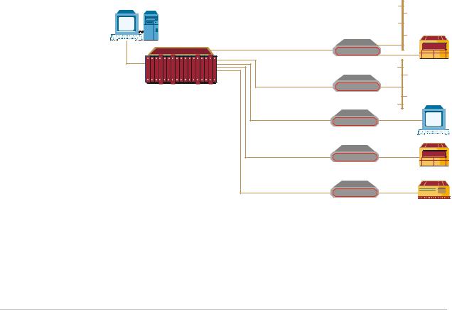
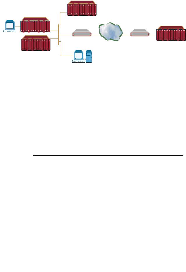
Application
Figure 1-1 shows an application of Backbone Data Distribution up to Customer’s Premises.
SNMP
Management
Station
HDSL |
|
HCD-E1 |
PABX |
MSDSL |
|
LRS-24 |
|
ASMi-51 |
|
IDSL |
|
ASMi-31-2 |
|
Fiber |
|
FOMi-E1/T1 |
PABX |
|
|
Fiber |
HSSI |
FOMi-E3 |
Router |
Figure 1-1. Backbone Data Distribution up to Customer’s Premises
Figure 1-2 shows an application of Management of Local and Remote Distribution Nodes.
Overview 1-3
Order from: Cutter Networks |
Ph:727-398-5252/Fax:727-397-9610 |
www.bestdatasource.com |

Chapter 1 Introduction |
LRS-24 Installation and Operation Manual |
|
|
Central
Management
Station
Dial-up
LRS-24 Modem
 PSTN
PSTN 

ADM or
Frame Relay Switch
|
|
|
|
|
|
|
|
|
|
|
|
|
|
|
|
|
|
|
|
|
|
|
|
|
|
|
|
|
|
|
|
|
|
|
|
|
|
|
|
|
|
|
|
|
|
|
|
|
|
|
|
|
|
|
|
|
|
|
|
|
|
|
|
|
|
|
|
|
|
|
|
|
|
|
|
|
|
|
|
|
|
|
|
|
|
|
|
|
|
|
|
|
|
|
|
|
|
PBX |
|
|
|
|
|
|
|
|
|
|
LRS-24 |
|
|
|
|
|
|
|
|
|
|
|
|
|
|
|
|
|
|
PBX |
|
|
|
|
|
||||||
|
|
|
|
|
|
||||||||
|
|
|
|
|
|
|
|
OP-XL |
|
|
|
||
PBX |
|
|
|
|
|
|
|
|
|
|
|||
|
|
|
|
|
|
|
|
|
|
|
LRS-24 |
|
|
|
|
|
|
|
|
|
|
|
|
|
|
|
|
|
|
LRS-24 |
Backbone |
Local SNMP |
|
|
Management |
|
|
Station |
Switch |
ADM or Frame |
|
|
Relay Switch |
|
LRS-24 |
|
Modem |
Router |
Router
Switch
MP2100
Figure 1-2. Management of Local and Remote Distribution Nodes
Features
LRS-24 is a high-density, fully modular design with front-panel access to all the functions. It supports up to 48 user modules in addition to redundant power supply and management access modules.
It combines different technologies in a centrally-managed rack: DSL, fiber and baseband.
LRS-24 offers single-point management access to the individual equipment modules installed in the hub, and to the remote equipment units connected by links to these modules. LRS-24 supports SNMP management, as well as management by means of an ASCII terminal. No special software is required for the terminal, which is controlled by the management software of the modules installed in LRS-24.
Clock signals are distributed from an external source (station clock) to all the equipment modules installed in the hub.
There is a standard set of regulated supply voltages. Power supply redundancy ensures continuous availability of power.
The unit supports remote (phantom) feed of equipment connected to LRS-24.
The mechanical design separates user hardware modules from interface (connector) modules, facilitates maintenance tasks.
The form factor is suitable for installation in standard 300 mm and 600 mm ETSI racks; can be easily adapted for installation in 19" racks.
The flexible modular construction and management capabilities that are available for the equipment installed in LRS-24 enable the user to easily configure individual systems for specific requirements and applications.
1-4 Overview
Order from: Cutter Networks |
Ph:727-398-5252/Fax:727-397-9610 |
www.bestdatasource.com |

LRS-24 Installation and Operation Manual |
Chapter 1 Introduction |
|
|
Remote Management
The modem cards in the LRS-24 can be remotely managed by the RADview-HPOV SNMP management system, the PC-based RADview-PC/MDM management system or by a dumb terminal. The same RADview application can manage the LRS-24, modems in the hub and other RAD products.
Audible and visual indicators provide status of alarms and tests at the network, card and port levels, and include all links connected to the hub. Alarms are automatically logged and presented upon request, unless otherwise masked.
RADview-HPOV SNMP Management System
Both electrical and fiber optic modem cards can be managed by the RADview-HPOV SNMP management system. All cards in the hub, except for ASM-40CD, have remote control abilities for monitoring and/or controlling remote units, and several types of cards contain an internal SNMP agent. In some cases, managed cards can work opposite non-manageable modems.
RADview-HPOV management is available for modules with or without integrated SNMP agent, via the SNMP Control Module (CM-2). The RADview-HPOV station is connected to LRS-24 via an integrated Ethernet connection on the CM-2 module; CM-2 acts as a proxy SNMP agent for those cards without an agent.
RADview-PC/MDM Management System
The RADview-PC/MDM management station communicates with LRS-24 using out-of-band communication via Ethernet.
The RADview-PC/MDM has a windows-based Graphical User Interface (GUI) platform for LAN and WAN networks. The graphical user interface allows configuration with easy-to-use operations on graphical representations of the hub. The configuration can be performed at the port, card, hub and network levels.
Management by Dumb Terminal
LRS-24 can also be managed from a dumb terminal. Control Module CM-1 is used for ASCII terminal management of modules with SNMP agent on-board, such as HTU-E1C.
Clock
Both control modules, CM-1 and CM-2, have a station clock connection enabling clock distribution to all cards, so that all cards can be synchronized to the same station clock. Refer to the specific card operation manual for a description of station clock support.
Power Supplies
LRS-24 operates with single or dual power supplies: AC or DC. Each power supply supports a full rack of cards of any combination. The redundant power supply can be replaced during operation, without affecting the system performance
(hotswapping).
Overview 1-5
Order from: Cutter Networks |
Ph:727-398-5252/Fax:727-397-9610 |
www.bestdatasource.com |

Chapter 1 Introduction |
LRS-24 Installation and Operation Manual |
|
|
|
|
|
|
|
|
|
|
1.2 Physical Description
Chassis Description
There are two different physical versions of LRS-24: LRS-24B and LRS-24F.
LRS-24B ANSI UNIT
LRS-24B is a modular chassis suitable for installation in standard ANSI racks. It has a height of 200 mm (4U). The chassis has physical slots arranged on the front and back sides:
•The front side accepts 4U-high functional modules (the modules that perform the various processing functions).
•The back side accepts 2U-high interface modules which contain the connectors used to access the modules on the front side.
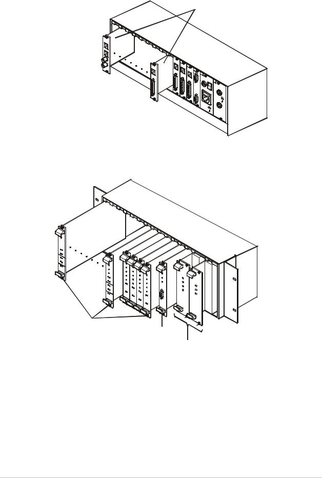
Figure 1-3 shows a 3-dimensional view of LRS-24B.
1-6 |
Physical Description |
Order from: Cutter Networks |
Ph:727-398-5252/Fax:727-397-9610 |
www.bestdatasource.com |

LRS-24 Installation and Operation Manual |
Chapter 1 Introduction |
|
|
O |
Rear View
Front View
Figure 1-3. LRS-24B 3-D View
Figure 1-4 shows the LRS-24B enclosure with the Interface Modules, User
Modules, Control Logic Module, and Power Supply Module.
Physical Description |
1-7 |
Order from: Cutter Networks |
Ph:727-398-5252/Fax:727-397-9610 |
www.bestdatasource.com |
Chapter 1 Introduction |
LRS-24 Installation and Operation Manual |
|
|
Interface Modules
LRS-24B Rear Section
User Modules
Control Logic
Module
Power Supply
(PS)
LRS-24 Front Section
Figure 1-4. LRS-24B Enclosure
1-8 |
Physical Description |
Order from: Cutter Networks |
Ph:727-398-5252/Fax:727-397-9610 |
www.bestdatasource.com |
LRS-24 Installation and Operation Manual |
Chapter 1 Introduction |
|
|
LRS-24F ETSI UNIT
LRS-24F is a modular chassis suitable for installation in standard ETSI racks, having a height of 300 mm (6U). The chassis has physical slots arranged in two rows:
•The lower row accepts 4U-high functional modules (the modules that perform the various processing functions).
•The top row accepts 2U-high interface modules, which contain the connectors used to access the modules in the lower row. The interface modules enable the connection of cables from the front side, and thus functional modules can be easily removed for maintenance without disconnecting cables.
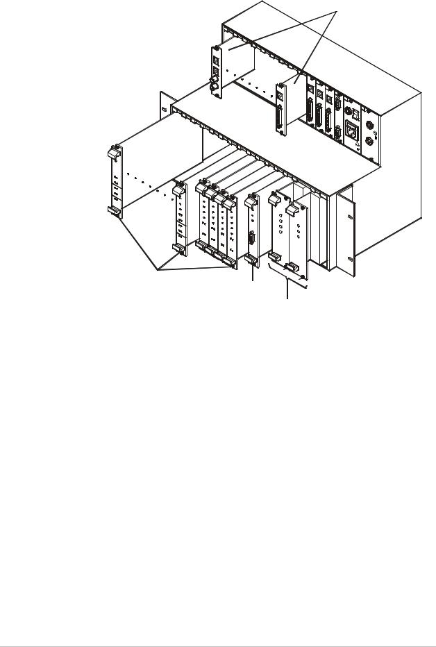
Figure 1-5 shows a 3-dimensional view of LRS-24F.
O |
Figure 1-5. LRS-24F 3-D View
LRS-24F Enclosure
Figure 1-6 shows the LRS-24F enclosure including User Modules and Interface Modules, Control Logic module, and Power Supply module.
Physical Description |
1-9 |
Order from: Cutter Networks |
Ph:727-398-5252/Fax:727-397-9610 |
www.bestdatasource.com |
Chapter 1 Introduction |
LRS-24 Installation and Operation Manual |
|
|
Interface Modules
User Modules
CONTROL LOGIC
Module
Power Supply
(PS)
Figure 1-6. LRS-24F Enclosure
LRS-24 Module Slots
The LRS-24F enclosure has a lower section for the functional modules and a top section for interface modules. The LRS-24B enclosure has a front section for the functional modules and a rear section for interface modules.
Each section has 15 module slots:
•Two slots are reserved for PS modules.
•One slot is reserved for the common logic module (CM-1 or CM-2).
•The other 12 slots are intended for user (I/O) modules. Each I/O slot can accept any type of I/O module. The modules are inserted from the front side. The top section of LRS-24F (back section of LRS-24B) includes slots for the interface modules.
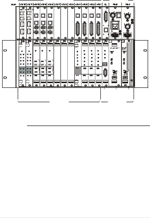
Front View
Figure 1-7 shows a typical front view of the LRS-24F enclosure, and identifies the slots and their use. Note the labels that designate the type of module that can be installed in each slot.
1-10 Physical Description
Order from: Cutter Networks |
Ph:727-398-5252/Fax:727-397-9610 |
www.bestdatasource.com |
LRS-24 Installation and Operation Manual |
Chapter 1 Introduction |
|
|
Internal Modules |
Internal Modules for |
for User Modules |
System Slots |
1 |
|
1 |
|
LRSI-F3 |
LRSI-F3 LRSI-F3 |
|
|
|
LRSI-F2 |
LRSI-F2 LRSI-F2 |
LRSI-F2 LRSI-F1-CM2 |
LRSI-F-PSP / 230 / 115 |
LRSI-F-PSP / 48 |
|||||||||
|
|
|
|
|
|
|
|
|
|
|
|
|
|
|
|
|
S |
PHANTOM |
POWER |
PHANTOM |
||
|
|
|
|
LINE |
|
LINE |
|
LINE |
|
|
|
|
LINE |
LINE |
LINE |
LINE |
|
|
T |
150V |
||
|
|
|
|
|
|
|
|
|
|
|
|
|
|
150V |
||||||||
|
|
|
|
|
|
|
|
|
|
|
|
A |
|
|
||||||||
|
|
|
|
|
|
|
|
|
|
|
|
|
|
|
|
|
|
|
T |
|
|
|
2 |
|
2 |
|
|
|
|
|
|
|
|
|
|
|
|
|
|
|
|
I |
|
|
|
|
|
|
|
|
|
|
|
|
|
|
|
|
|
|
|
|
O |
|
|
|
||
|
|
|
|
|
|
|
|
|
|
|
|
|
|
|
|
|
|
|
|
|
|
|
|
|
|
|
|
|
|
|
|
|
|
|
|
|
|
|
|
|
|
N |
|
|
|
|
|
|
|
|
|
|
|
|
|
|
|
|
|
DCE |
DCE |
DCE |
|
|
C |
|
|
|
DCE-1 |
DCE-1 |
|
|
|
|
|
|
|
|
|
DCE |
|
|
L |
|
|
|
|||||
|
|
|
|
|
|
|
|
|
|
|
|
|
|
|
|
|
|
|
K |
|
|
|
|
|
|
|
|
|
|
|
|
|
|
|
|
|
|
|
|
|
|
|
|
|
48V |
|
|
|
|
|
|
|
|
|
|
|
|
|
|
|
|
|
ETHERNET |
10BT |
MANAGEMENT |
|
|
|
DCE-2 |
DCE-2 |
|
|
|
|
|
|
|
|
|
|
|
|
|
|
|
|
|
||||
|
|
|
|
|
|
|
|
|
|
|
|
|
|
|
|
|
|
100-230 VAC |
CHASS |
|||
|
|
|
|
|
|
|
|
|
|
|
|
|
|
|
|
|
|
GND |
||||
|
|
|
|
|
|
|
|
|
|
|
|
|
|
|
|
|
|
3A T 250V |
|
|||
|
|
|
|
|
|
|
|
|
|
|
|
|
|
|
|
|
|
|
|
|
||
I/O12 |
|
I/O11 |
|
I/O10 |
|
I/O 9 |
|
I/O 8 |
|
I/O 7 |
I/O 6 |
I/O 5 |
I/O 4 |
I/O 3 |
I/O 2 |
I/O 1 |
CL |
|
|
PS-B |
|
PS-A |
POWER |
POWER |
POWER |
|
POWER |
|
POWER |
|
|
|
|
POWER |
POWER |
POWER |
POWER |
POWER |
|
|
|
|
|||
|
|
|
|
|
|
|
|
|
|
|
|
|
|
|
|
|
|
|||||
TD1 |
TD2 |
TD1 |
TD2 |
|
|
|
|
|
|
|
|
|
TD |
TD |
TD |
TD |
|
TD |
|
|
|
|
|
|
|
|
|
|
|
|
|
|
|
|
|
|
|
|
|
|
|
|
|
|
|
RD1 RD2 |
RD1 RD2 |
|
|
|
|
|
|
|
|
|
RD |
RD |
RD |
RD |
|
RD |
|
|
|
|
||
|
|
|
|
|
|
|
|
|
|
|
|
|
|
|
|
|
|
|||||
RTS1 RTS2 |
RTS1 RTS2 |
ALARMS |
|
ALARMS |
|
ALARMS |
|
|
|
|
RTS |
RTS |
RTS |
RTS |
|
|
|
|
|
|
||
|
|
|
|
|
|
|
|
|
|
|
|
|
|
|
|
|
||||||
DCD1 DCD2 |
DCD1DCD2 |
|
E |
|
E |
|
E |
|
|
|
|
|
|
|
STAT / ADD |
|
|
|
|
|||
|
|
|
|
|
|
DCD |
|
|
|
|
|
|
|
|
|
|||||||
|
|
|
|
SIGNAL |
1 |
SIGNAL |
1 |
SIGNAL |
1 |
|
|
|
DCD |
DCD |
DCD |
|
|
|
|
|
|
|
SYNC LOSS |
SYNC LOSS |
SYNC LOSS |
SYNC LOSS |
SYNC LOSS |
|
|
|
LINE |
LINE |
LINE |
LINE |
CONTROL |
|
|
|
|
||||||
|
|
|
|
|
|
|
|
|
||||||||||||||
1 |
2 |
1 |
2 |
A B |
|
A B |
|
A B |
|
|
|
|
LOS QLTY |
LOS QLTY |
LOS QLTY |
LOS QLTY |
R |
|
|
|
|
|
TEST |
TEST |
QUALITY |
|
QUALITY |
|
QUALITY |
|
|
|
|
|
|
|
|
S |
|
|
|
|
|
||
1 |
2 |
1 |
2 |
A B |
|
A B |
|
A B |
|
|
|
|
|
|
|
|
2 |
|
|
|
|
|
|
|
|
|
LINE |
|
LINE |
|
LINE |
|
|
|
|
|
|
|
|
3 |
|
|
|
|
|
|
|
|
|
|
|
|
|
|
|
|
|
|
|
|
|
|
2 |
|
|
|
|
|
ERR1 ERR2 ERR1 ERR2 |
TEST ALARM TEST ALARM TEST ALARM |
|
|
|
TESTERR |
TEST ALARM TEST ALARM TEST ALARM |
|
|
|
|
|
|
||||||||||
ASM-40CD |
ASM-40CD |
HTU-E1 |
|
HTU-E1 |
|
HTU-T1 |
|
|
|
|
ASMi-50C |
ASMi-450 |
ASMi-450 |
ASMi-450 |
|
CM-2 |
|
|
|
|
||
|
Control |
Redundant |
|
Power |
|
|
|||
|
Logic |
Power Supply |
Supply |
|
|
Module |
(Option) |
|
|
User Modules |
System Slots |
|
||
Figure 1-7. LRS-24F Enclosure, Typical Front View
1.3 Functional Description
The main functions of the LRS-24 chassis are to provide mechanical support and connections between the various modules.
The main modules are:
•Power Supply (PS) Modules
•Common Logic Modules
•I/O (User) Modules.
Power Supply (PS) Modules
The LRS-24 hub can be powered by AC and DC power supply modules. Two power supply modules can be installed to provide redundancy. The following types of AC and DC power supply modules are available for LRS-24:
•AC power supply module, PS-LRS/230/115 – operates on 100 to 240 VAC nominal, and provides a maximum total output power of 120W.
Functional Description |
1-11 |
Order from: Cutter Networks |
Ph:727-398-5252/Fax:727-397-9610 |
www.bestdatasource.com |

Chapter 1 Introduction |
LRS-24 Installation and Operation Manual |
|
|
•DC power supply module, PS-LRS/48 – operates on –48 VDC, and provides a maximum total power of 120W.
The PS modules are installed in dedicated chassis slots. The chassis has two PS slots, enabling the installation of two PS modules, for redundancy. When both modules are operational, they share the load; in case of failure or loss of input power, the remaining module continues to supply the power alone. Switchover is thus automatic and does not interrupt normal operation.
A redundant module can be installed in an operating enclosure without turning off the enclosure power. An AC and a DC PS module can be installed simultaneously.
Several I/O modules installed in the chassis can supply remote (phantom) feed voltage for the remote equipment connected to the modules installed in the LRS-24. This voltage must be provided by an external source.
RAD offers a standalone unit, LRS-PS-FEED, that can provide the required voltage for the remote power source. LRS-PS-FEED is explained in Appendix B of this manual.
The phantom feed voltage is connected through the power supply interface module and through the corresponding PS to the internal phantom feed distribution bus of the LRS-24.
Common Logic Modules
LRS-24 is managed by either of the two CM modules, CM-1 or CM-2. The main functions of the two module types are:
•Interfacing between a management facility and the equipment modules installed in LRS-24. The CM-1 module only supports management by means of a supervision terminal; the CM-2 module also supports network management stations.
•Distribution of an external clock signal (station clock) to the equipment modules. The station clock interface circuits of the common logic modules have the following user-selectable modes:
−T1 DSU interface per ANSI TR-62411 and ANSI T1.403, with 100Ω balanced T1 line interface. This mode accepts an AMI-coded clock signal of 1544 kHz. The maximum signal attenuation is 10 dB.
−E1 DSU interface per ITU-T Rec. G.703, which accepts an
HDB3-coded clock signal of 2048 kHz. The E1 interface can be configured to operate as a 120Ω balanced line interface, or a 75Ω unbalanced interface. The maximum line attenuation is 10 dB.
−Square interface per TTL input.
The recovered clock signal is returned toward the equipment providing the clock signal (remote loop condition, controlled by a user jumper).
1-12 Functional Description
Order from: Cutter Networks |
Ph:727-398-5252/Fax:727-397-9610 |
www.bestdatasource.com |

LRS-24 Installation and Operation Manual |
Chapter 1 Introduction |
|
|
Management
CM-1 Management Capabilities
An ASCII terminal can be used as a supervision terminal to manage the CM-1 module. The supervision terminal is connected to one of the RS-232 asynchronous serial supervisory ports (one port is located on the CM-1 module itself and the second port is located on the interface module serving the CM-1 module).
The CM-1 module operates as an interface module that does not process the management information, but only transfers the management traffic transparently to the modules installed in the LRS-24. Therefore, the supervision terminal is controlled by the software stored in the managed modules, and the management capabilities depend on the capabilities of the managed modules.
For a description of the management activities supported by a terminal connected to the CM-1 module, refer to the Installation and Operation Manuals available for the modules installed in LRS-24.
CM-2 Management Capabilities
The CM-2 module enhances the management capabilities available to the user by including three different management functions:
•SNMP management. For SNMP management, the CM-2 module communicates via an additional management interface located on the interface module serving the CM-2 module. Currently, two types of interfaces are available: an Ethernet 10BaseT interface (for UTP and STP media), and an Ethernet 10Base2 interface (for coaxial media). This configuration is illustrated in Figure 1-8.
•SNMP management communication with an LRS-24 module that includes an SNMP agent is handled by an internal SNMP agent and bridge/router located on the CM-2 module. To enable SNMP management of modules without SNMP agents, the CM-2 module includes a proxy agent that converts the management traffic to the proprietary internal protocol used to manage such modules.
•Management by an ASCII terminal operating as a supervision terminal. The terminal, which is controlled by the software stored in the managed modules, connects to the serial RS-232 asynchronous supervisory port located on the CM-2 module (see Figure 1-8). The management capabilities available through the terminal are similar to those available through the CM-1 module.
•Management by means of Telnet. The CM-2 also supports the Telnet protocol. This enables remote management via the same command line interface used with a supervision terminal. Telnet uses TCP/IP communication through the Ethernet port of the CM-2 card.
•Management via RS-232 by Slip Protocol with SNMP management.
Functional Description |
1-13 |
Order from: Cutter Networks |
Ph:727-398-5252/Fax:727-397-9610 |
www.bestdatasource.com |
Chapter 1 Introduction |
LRS-24 Installation and Operation Manual |
|
|
|
LRS-24 |
|
|
|
LRS-24 |
|
|
|
|
WAN |
|
Supervision |
MBE |
MBE |
|
Terminal |
|||
|
|
||
|
|
LRS-24 |
|
|
LRS-24 |
|
Management
Station
Figure 1-8. Basic Management Configuration for LRS-24 with CM-2 Modules
I/O (User) Modules
LRS-24 can be equipped with various types of input/output (I/O) modules to provide the required system functions. These include ASMi-24C, ASMi-31C, ASMi-31CQ, ASMi-50C, ASMi-450C, HTU-E1C, FOMi-40C, FOMi-E1/T1C, FOMi-E3C, FOMi-T3C, MTMi-20C, FOMi-40CD, ASM-40CD, FOMi-E1/T1/CD, ASMi-50CD, and ASMi-51CQ.
The range of modules and options available for LRS-24 is continuously expanding. Refer to the Installation and Operation Manuals of the corresponding modules for information.
1.4 Technical Specifications
Chassis |
Number of |
15 – Each slot is connected to an interface module slot |
Characteristics |
Functional Module |
|
|
Slots |
|
|
Slot Usage |
2 power supply slots |
|
|
1 common logic slot |
|
|
12 identical slots for I/O (user) modules |
Power |
Module |
100 – 240 VAC nominal, 50/60 Hz, maximum 160W |
|
PS-LRS/230/115 |
|
|
Module PS-LRS/48 |
–48 VDC nominal, maximum 160W |
|
Remote (Phantom) |
LRS-PS-FEED standalone unit |
|
Source |
|
1-14 Technical Specifications
Order from: Cutter Networks |
Ph:727-398-5252/Fax:727-397-9610 |
www.bestdatasource.com |

LRS-24 Installation and Operation Manual Chapter 1 Introduction
External Clock Interface |
|
|
T1 Mode |
Type |
T1 |
|
Clock Rate |
1.544 MHz |
|
Line Interface |
100Ω, balanced |
|
Line Code |
Bipolar AMI |
|
Receive Level |
0 through -10 dB |
|
Transmit Level |
±3V ±10%, balanced |
E1 Mode |
Type |
E1 |
|
Bit Rate |
2.048 MHz |
|
Line Interface |
120Ω, balanced |
|
|
75Ω, unbalanced |
|
Line Code |
AMI |
|
Receive Level |
0 through -10 dB |
|
Transmit Level |
±3V ±10%, balanced |
|
|
±2.73V ±10%, unbalanced |
|
Square |
Minimum 2.2V peak-to-peak amplitude |
CM-1 Management Interface |
|
|
|
Functionality |
Transparent interfacing to internal management ports of |
|
|
I/O modules |
|
Hardware |
RS-232 asynchronous port, compatible with |
|
|
VT-52, VT-100, FREEDOM-100, FREEDOM-110, |
|
|
FREEDOM-220 |
|
|
Data rates up to 9.6 kbps |
|
|
Word format: software-configurable |
|
Software |
Terminal driven by software stored in each I/O module |
CM-2 Management Interface |
|
|
|
Functionality |
Terminal management interface |
|
|
SNMP agent with internal bridge/router and ARP server |
|
|
for internal modules |
Protocol conversion between internal management protocols of I/O modules and external management function
Technical Specifications |
1-15 |
Order from: Cutter Networks |
Ph:727-398-5252/Fax:727-397-9610 |
www.bestdatasource.com |

Chapter 1 Introduction |
LRS-24 Installation and Operation Manual |
|
|
Hardware
Asynchronous Port
Characteristics
Software
Ethernet 10BaseT interface for UTP and STP media
Ethernet 10Base2 interface for coaxial media
RS-232 asynchronous port, compatible with VT-52, VT-100, FREEDOM-100, FREEDOM-110, and FREEDOM-220
Data rate: 38.4 kbps
Word format: one start bit, eight data bits, no parity, one stop bit
SNMP over Ethernet LAN port
Terminal interface controlled by software stored in the
CM-2 module
Physical Data |
LRS-24F |
|
|
|
|
|
Height |
299 |
mm/ 11.8 |
in |
|
|
Width including |
533.8 |
mm/ |
21 |
in |
|
brackets |
|
|
|
|
|
Width without |
437.8 |
mm/ 17.2 |
in |
|
|
brackets |
|
|
|
|
|
Depth |
252 |
mm/ |
9.9 |
in |
|
LRS-24B |
|
|
|
|
|
Height |
177 |
mm/ |
7.0 |
in |
|
Width including |
533.8 |
mm/ |
21 |
in |
|
brackets |
|
|
|
|
|
Width without |
437.8 |
mm/ 17.2 |
in |
|
|
brackets |
|
|
|
|
|
Depth |
324 |
mm/ 12.8 |
in |
|
Environment |
|
32 F to 113 F / 0 C to 45 C |
|||
|
Operating |
° |
° |
° |
° |
|
Temperature |
|
|
|
|
|
Storage |
0°F to 150°F / –20°C to +70°C |
|||
|
Temperature |
|
|
|
|
|
Humidity |
Up to 90%, non-condensing |
|||
1-16 Technical Specifications
Order from: Cutter Networks |
Ph:727-398-5252/Fax:727-397-9610 |
www.bestdatasource.com |

Chapter 2
Installation and Setup
This chapter provides installation and operation instructions for the LRS-24 system, and the basic system configuration of the power supply (PS) and common logic (CM-1 and CM-2) modules. It includes the following topics:
•Site requirements and prerequisites
•Equipment needed
•Package contents
•Installation and setup
•Interfaces and connections
•Initial operation and basic checks
See Chapter 3 for management via a CM-1 module and Chapter 4 for management via a CM-2 module.
2.1 Introduction
If LRS-24 includes a CM-2 module, you must configure management parameters of the CM-2 module before the management functions are operable. This procedure is explained in Chapter 4.
After installing the basic system, install the user modules according to the system installation plan, as explained in the Installation and Operation Manual of the individual modems.
No internal settings, adjustment, maintenance, and repairs may be performed by either the operator or the user; such activities may be performed only by a
skilled technician who is aware of the hazards involved.
Warning Always observe standard safety precautions during installation, operation, and maintenance of this product.
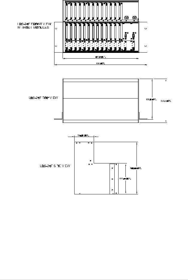
Mechanical Data
Figure 2-1 provides mechanical data on the LRS-24F chassis. Figure 2-2 provides mechanical data on the LRS-24B chassis.
Introduction 2-1
Order from: Cutter Networks |
Ph:727-398-5252/Fax:727-397-9610 |
www.bestdatasource.com |
Chapter 2 Installation and Setup |
|
|
|
|
|
|
|
|
|
|
|
|
|
|
|
|
|
|
|
|
|
|
|
|
|
|
|
|
|
|
|
|
|
|
|
|
|
|
LRS-24 Installation and Operation Manual |
|||||||||||||||||||||||||||||||||||||||||||||||
|
|
|
|
|
|
|
|
|
|
|
|
|
|
|
|
|
|
|
|
|
|
|
|
|
|
|
|
|
|
|
|
|
|
|
|
|
|
|
|
|
|
|
|
|
|
|
|
|
|
|
|
|
|
|
|
|
|
|
|
|
|
|
|
|
|
|
|
|
|
|
|
|
|
|
|
|
|
|
|
|
|
|
|
|
|
|
|
|
|
|
|
|
|
|
|
|
|
|
|
|
|
|
|
|
|
|
|
|
|
|
|
|
|
|
|
|
|
|
|
|
|
|
|
|
|
|
|
|
|
|
|
|
|
|
|
|
|
|
|
|
|
|
|
|
|
|
|
|
|
|
|
|
|
|
|
|
|
|
|
|
|
|
|
|
|
|
|
|
|
|
|
|
|
|
|
|
|
|
|
|
|
|
|
|
|
|
|
|
|
|
|
|
|
|
|
|
|
|
|
|
|
|
|
|
|
|
|
|
|
|
|
|
|
|
|
|
|
|
|
|
|
|
|
|
|
|
|
|
|
|
|
|
|
|
|
|
|
|
|
|
|
|
|
|
|
|
|
|
|
|
|
|
|
|
|
|
|
|
|
|
|
|
|
|
|
|
|
|
|
|
|
|
|
|
|
|
|
|
|
|
|
|
|
|
|
|
|
|
|
|
|
|
|
|
|
|
|
|
|
|
|
|
|
|
|
|
|
|
|
|
|
|
|
|
|
|
|
|
|
|
|
|
|
|
|
|
|
|
|
|
|
|
|
|
|
|
|
|
|
|
|
|
|
|
|
|
|
|
|
|
|
|
|
|
|
|
|
|
|
|
|
|
|
|
|
|
|
|
|
|
|
|
|
|
|
|
|
|
|
|
|
|
|
|
|
|
|
|
|
|
|
|
|
|
|
|
|
|
|
|
|
|
|
|
|
|
|
|
|
|
|
|
|
|
|
|
|
|
|
|
|
|
|
|
|
|
|
|
|
|
|
|
|
|
|
|
|
|
|
|
|
|
|
|
|
|
|
|
|
|
|
|
|
|
|
|
|
|
|
|
|
|
|
|
|
|
|
|
|
|
|
|
|
|
|
|
|
|
|
|
|
|
|
|
|
|
|
|
|
|
|
|
|
|
|
|
|
|
|
|
|
|
|
|
|
|
|
|
|
|
|
|
|
|
|
|
|
|
|
|
|
|
|
|
|
|
|
|
|
|
|
|
|
|
|
|
|
|
|
|
|
|
|
|
|
|
|
|
|
|
|
|
|
|
|
|
|
|
|
|
|
|
|
|
|
|
|
|
|
|
|
|
|
|
|
|
|
|
|
|
|
|
|
|
|
|
|
|
|
|
|
|
|
|
|
|
|
|
|
|
|
|
|
|
|
|
|
|
|
|
|
|
|
|
|
|
|
|
|
|
|
|
|
|
|
|
|
|
|
|
|
|
|
|
|
|
|
|
|
|
|
|
|
|
|
|
|
|
|
|
|
|
|
|
|
|
|
|
|
|
|
|
|
|
|
|
|
|
|
|
|
|
|
|
|
|
|
|
|
|
|
|
|
|
|
|
|
|
|
|
|
|
|
|
|
|
|
|
|
|
|
|
|
|
|
|
|
|
|
|
|
|
|
|
|
|
|
|
|
|
|
|
|
|
|
|
|
|
|
|
|
|
|
|
|
|
|
|
|
|
|
|
|
|
|
|
|
|
|
|
|
|
|
|
|
|
|
|
|
|
|
|
|
|
|
|
|
|
|
|
|
|
|
|
|
|
|
|
|
|
|
|
|
|
|
|
|
|
|
|
|
|
|
|
|
|
|
|
|
|
|
|
|
|
|
|
|
|
|
|
|
|
|
|
|
|
|
|
|
|
|
|
|
|
|
|
|
|
|
|
|
|
|
|
|
|
|
|
|
|
|
|
|
|
|
|
|
|
|
|
|
|
|
|
|
|
|
|
|
|
|
|
|
|
|
|
|
|
|
|
|
|
|
|
|
|
|
|
|
|
|
|
|
|
|
|
|
|
|
|
|
|
|
|
|
|
|
|
|
|
|
|
|
|
|
|
|
|
|
|
|
|
|
|
|
|
|
|
|
|
|
|
|
|
|
|
|
|
|
|
|
|
|
|
|
|
|
|
|
|
|
|
|
|
|
|
|
|
|
|
|
|
|
|
|
|
|
|
|
|
|
|
|
|
|
|
|
|
|
|
|
|
|
|
|
|
|
|
|
|
|
|
|
|
|
|
|
|
|
|
|
|
|
|
|
|
|
|
|
|
|
|
|
|
|
|
|
|
|
|
|
|
|
|
|
|
|
|
|
|
|
|
|
|
|
|
|
|
|
|
|
|
|
|
|
|
|
|
|
|
|
|
|
|
|
|
|
|
|
|
|
|
|
|
|
|
|
|
|
|
|
|
|
|
|
|
|
|
|
|
|
|
|
|
|
|
|
|
|
|
|
|
|
|
|
|
|
|
|
|
|
|
|
|
|
|
|
|
|
|
|
|
|
|
|
|
|
|
|
|
|
|
|
|
|
|
|
|
|
|
|
|
|
|
|
|
|
|
|
|
|
|
|
|
|
|
|
|
|
|
|
|
|
|
|
|
|
|
|
|
|
|
|
|
|
|
|
|
|
|
|
|
|
|
|
|
|
|
|
|
|
|
|
|
|
|
|
|
|
|
|
|
|
|
|
|
|
|
|
|
|
|
|
|
|
|
|
|
|
|
|
|
|
|
|
|
|
|
|
|
|
|
|
|
|
|
|
|
|
|
|
|
|
|
|
|
|
|
|
|
|
|
|
|
|
|
|
|
|
|
|
|
|
|
|
|
|
|
|
|
|
|
|
|
|
|
|
|
|
|
|
|
|
|
|
|
|
|
|
|
|
|
|
|
|
|
|
|
|
|
|
|
|
|
|
|
|
|
|
|
|
|
|
|
|
|
|
|
|
|
|
|
|
|
|
|
|
|
|
|
|
|
|
|
|
|
|
|
|
|
|
|
|
|
|
|
|
|
|
|
|
|
|
|
|
|
|
|
|
|
|
|
|
|
|
|
|
|
|
|
|
|
|
|
|
|
|
|
|
|
|
|
|
|
|
|
|
|
|
|
|
|
|
|
|
|
|
|
|
|
|
|
|
|
|
|
|
|
|
|
|
|
|
|
|
|
|
|
|
|
|
|
|
|
|
|
|
|
|
|
|
|
|
|
|
|
|
|
|
|
|
|
|
|
|
|
|
|
|
|
|
|
|
|
|
|
|
|
|
|
|
|
|
|
|
|
|
|
|
|
|
|
|
|
|
|
|
|
|
|
|
|
|
|
|
|
|
|
|
|
|
|
|
|
|
|
|
|
|
|
|
|
|
|
|
|
|
|
|
|
|
|
|
|
|
|
|
|
|
|
|
|
|
|
|
|
|
|
|
|
|
|
|
|
|
|
|
|
|
|
|
|
|
|
|
|
|
|
|
|
|
|
|
|
|
|
|
|
|
|
|
|
|
|
|
|
|
|
|
|
|
|
|
|
|
|
|
|
|
|
|
|
|
|
|
|
|
|
|
|
|
|
|
|
|
|
|
|
|
|
|
|
|
|
|
|
|
|
|
|
|
|
|
|
|
|
|
|
|
|
|
|
|
|
|
|
|
|
|
|
|
|
|
|
|
|
|
|
|
|
|
|
|
|
|
|
|
|
|
|
|
|
|
|
|
|
|
|
|
|
|
|
|
|
|
|
|
|
|
|
|
|
|
|
|
|
|
|
|
|
|
|
|
|
|
|
|
|
|
|
|
|
|
|
|
|
|
|
|
|
|
|
|
|
|
|
|
|
|
|
|
|
|
|
|
|
|
|
|
|
|
|
|
|
|
|
|
|
|
|
|
|
|
|
|
|
|
|
|
|
|
|
|
|
|
|
|
|
|
|
|
|
|
|
|
|
|
|
|
|
|
|
|
|
|
|
|
|
|
|
|
|
|
|
|
|
|
|
|
|
|
|
|
|
|
|
|
|
|
|
|
|
|
|
|
|
|
|
|
|
|
|
|
|
|
|
|
|
|
|
|
|
|
|
|
|
|
|
|
|
|
|
|
|
|
|
|
|
|
|
|
|
|
|
|
|
|
|
|
|
|
|
|
|
|
|
|
|
|
|
|
|
|
|
|
|
|
|
|
|
|
|
|
|
|
|
|
|
|
|
|
|
|
|
|
|
|
|
|
|
|
|
|
|
|
|
|
|
|
|
|
|
|
|
|
|
|
|
|
|
|
|
|
|
|
|
|
|
|
|
|
|
|
|
|
|
|
|
|
|
|
|
|
|
|
|
|
|
|
|
|
|
|
|
|
|
|
|
|
|
|
|
|
|
|
|
|
|
|
|
|
|
|
|
|
|
|
|
|
|
|
|
|
|
|
|
|
|
|
|
|
|
|
|
|
|
|
|
|
|
|
|
|
|
|
|
|
|
|
|
|
|
|
|
|
|
|
|
|
|
|
|
|
|
|
|
|
|
|
|
|
|
|
|
|
|
|
|
|
|
|
|
|
|
|
|
|
|
|
|
|
|
|
|
|
|
|
|
|
|
|
|
|
|
|
|
|
|
|
|
|
|
|
|
|
|
|
|
|
|
|
|
|
|
|
|
|
|
|
|
|
|
|
|
|
|
|
|
|
|
|
|
|
|
|
|
|
|
|
|
|
|
|
|
|
|
|
|
|
|
|
|
|
|
|
|
|
|
|
|
|
|
|
|
|
|
|
|
|
|
|
|
|
|
|
|
|
|
|
|
|
|
|
|
|
|
|
|
|
|
|
|
|
|
|
|
|
|
|
|
|
|
|
|
|
|
|
|
|
|
|
|
|
|
|
|
|
|
|
|
|
|
|
|
|
|
|
|
|
|
|
|
|
|
|
|
|
|
|
|
|
|
|
|
|
|
|
|
|
|
|
|
|
|
|
|
|
|
|
|
|
|
|
|
|
|
|
|
|
|
|
|
|
|
|
|
|
|
|
|
|
|
|
|
|
|
|
|
|
|
|
|
|
|
|
|
|
|
|
|
|
|
|
|
|
|
|
|
|
|
|
|
|
|
|
|
|
|
|
|
|
|
|
|
|
|
|
|
|
|
|
|
|
|
|
|
|
|
|
|
|
|
|
|
|
|
|
|
|
|
|
|
|
|
|
|
|
|
|
|
|
|
|
|
|
|
|
|
|
|
|
|
|
|
|
|
|
|
|
|
|
|
|
|
|
|
|
|
|
|
|
|
|
|
|
|
|
|
|
|
|
|
|
|
|
|
|
|
|
|
|
|
|
|
|
|
|
|
|
|
|
|
|
|
|
|
|
|
|
|
|
|
|
|
|
|
|
|
|
|
|
|
|
|
|
|
|
|
|
|
|
|
|
|
|
|
|
|
|
|
|
|
|
|
|
|
|
|
|
|
|
|
|
|
|
|
|
|
|
|
|
|
|
|
|
|
|
|
|
|
|
|
|
|
|
|
|
|
|
|
|
|
|
|
|
Figure 2-1. LRS-24F Mechanical Diagram
2-2 Introduction
Order from: Cutter Networks |
Ph:727-398-5252/Fax:727-397-9610 |
www.bestdatasource.com |
Loading...