


 Loading...
Installation and Operation Manual
IPmux-11
TDM Pseudowire Access
Gateway
Version 2.00

IPmux-11
TDM Pseudowire Access Gateway
Version 2.00
Installation and Operation Manual
Notice
This manual contains information that is proprietary to RAD Data Communications Ltd. ("RAD"). No part of this publication may be reproduced in any form whatsoever without prior written approval by RAD Data Communications.
Right, title and interest, all information, copyrights, patents, know-how, trade secrets and other intellectual property or other proprietary rights relating to this manual and to the IPmux-11 and any software components contained therein are proprietary products of RAD protected under international copyright law and shall be and remain solely with RAD.
IPmux-11 is a registered trademark of RAD. No right, license, or interest to such trademark is granted hereunder, and you agree that no such right, license, or interest shall be asserted by you with respect to such trademark.
You shall not copy, reverse compile or reverse assemble all or any portion of the Manual or the IPmux11. You are prohibited from, and shall not, directly or indirectly, develop, market, distribute, license, or sell any product that supports substantially similar functionality as the IPmux-11, based on or derived in any way from the IPmux-11. Your undertaking in this paragraph shall survive the termination of this Agreement.
This Agreement is effective upon your opening of the IPmux-11 package and shall continue until terminated. RAD may terminate this Agreement upon the breach by you of any term hereof. Upon such termination by RAD, you agree to return to RAD the IPmux-11 and all copies and portions thereof.
For further information contact RAD at the address below or contact your local distributor.
|
International Headquarters |
North America Headquarters |
|
|
RAD Data Communications Ltd. |
RAD Data Communications Inc. |
|
|
24 Raoul Wallenberg St. |
900 Corporate Drive |
|
|
Tel Aviv 69719 Israel |
Mahwah, NJ 07430 USA |
|
|
Tel: 972-3-6458181 |
Tel: (201) 529-1100, Toll free: 1-800-444-7234 |
|
|
Fax: 972-3-6498250 |
Fax: (201) 529-5777 |
|
|
E-mail: market@rad.com |
E-mail: market@radusa.com |
|
|
|
|
|
© 1999–2006 RAD Data Communications Ltd. |
Publication No. 352-200-08/06 |
||
Limited Warranty
RAD warrants to DISTRIBUTOR that the hardware in the IPmux-11 to be delivered hereunder shall be free of defects in material and workmanship under normal use and service for a period of twelve (12) months following the date of shipment to DISTRIBUTOR.
If, during the warranty period, any component part of the equipment becomes defective by reason of material or workmanship, and DISTRIBUTOR immediately notifies RAD of such defect, RAD shall have the option to choose the appropriate corrective action: a) supply a replacement part, or b) request return of equipment to its plant for repair, or c) perform necessary repair at the equipment's location. In the event that RAD requests the return of equipment, each party shall pay one-way shipping costs.
RAD shall be released from all obligations under its warranty in the event that the equipment has been subjected to misuse, neglect, accident or improper installation, or if repairs or modifications were made by persons other than RAD's own authorized service personnel, unless such repairs by others were made with the written consent of RAD.
The above warranty is in lieu of all other warranties, expressed or implied. There are no warranties which extend beyond the face hereof, including, but not limited to, warranties of merchantability and fitness for a particular purpose, and in no event shall RAD be liable for consequential damages.
RAD shall not be liable to any person for any special or indirect damages, including, but not limited to, lost profits from any cause whatsoever arising from or in any way connected with the manufacture, sale, handling, repair, maintenance or use of the IPmux-11, and in no event shall RAD's liability exceed the purchase price of the IPmux-11.
DISTRIBUTOR shall be responsible to its customers for any and all warranties which it makes relating to IPmux-11 and for ensuring that replacements and other adjustments required in connection with the said warranties are satisfactory.
Software components in the IPmux-11 are provided "as is" and without warranty of any kind. RAD disclaims all warranties including the implied warranties of merchantability and fitness for a particular purpose. RAD shall not be liable for any loss of use, interruption of business or indirect, special, incidental or consequential damages of any kind. In spite of the above RAD shall do its best to provide error-free software products and shall offer free Software updates during the warranty period under this Agreement.
RAD's cumulative liability to you or any other party for any loss or damages resulting from any claims, demands, or actions arising out of or relating to this Agreement and the IPmux-11 shall not exceed the sum paid to RAD for the purchase of the IPmux-11. In no event shall RAD be liable for any indirect, incidental, consequential, special, or exemplary damages or lost profits, even if RAD has been advised of the possibility of such damages.
This Agreement shall be construed and governed in accordance with the laws of the State of Israel.
Product Disposal
To facilitate the reuse, recycling and other forms of recovery of waste equipment in protecting the environment, the owner of this RAD product is required to refrain from disposing of this product as unsorted municipal waste at the end of its life cycle. Upon termination of the unit’s use, customers should provide for its collection for reuse, recycling or other form of environmentally conscientious disposal.
General Safety Instructions
The following instructions serve as a general guide for the safe installation and operation of telecommunications products. Additional instructions, if applicable, are included inside the manual.
Safety Symbols
This symbol may appear on the equipment or in the text. It indicates potential safety hazards regarding product operation or maintenance to
operator or service personnel.
Warning
Danger of electric shock! Avoid any contact with the marked surface while the product is energized or connected to outdoor telecommunication lines.
.
Protective earth: the marked lug or terminal should be connected to the building protective earth bus.
|
Some products may be equipped with a laser diode. In such cases, a label |
|
|
with the laser class and other warnings as applicable will be attached near |
|
Warning |
the optical transmitter. The laser warning symbol may be also attached. |
|
Please observe the following precautions: |
||
|
•Before turning on the equipment, make sure that the fiber optic cable is intact and is connected to the transmitter.
•Do not attempt to adjust the laser drive current.
•Do not use broken or unterminated fiber-optic cables/connectors or look straight at the laser beam.
•The use of optical devices with the equipment will increase eye hazard.
•Use of controls, adjustments or performing procedures other than those specified herein, may result in hazardous radiation exposure.
ATTENTION: The laser beam may be invisible!
In some cases, the users may insert their own SFP laser transceivers into the product. Users are alerted that RAD cannot be held responsible for any damage that may result if non-compliant transceivers are used. In particular, users are warned to use only agency approved products that comply with the local laser safety regulations for Class 1 laser products.
Always observe standard safety precautions during installation, operation and maintenance of this product. Only qualified and authorized service personnel should carry out adjustment, maintenance or repairs to this product. No installation, adjustment, maintenance or repairs should be performed by either the operator or the user.
Handling Energized Products
General Safety Practices
Do not touch or tamper with the power supply when the power cord is connected. Line voltages may be present inside certain products even when the power switch (if installed) is in the OFF position or a fuse is blown. For DC-powered products, although the voltages levels are usually not hazardous, energy hazards may still exist.
Before working on equipment connected to power lines or telecommunication lines, remove jewelry or any other metallic object that may come into contact with energized parts.
Unless otherwise specified, all products are intended to be grounded during normal use. Grounding is provided by connecting the mains plug to a wall socket with a protective earth terminal. If an earth lug is provided on the product, it should be connected to the protective earth at all times, by a wire with a diameter of 18 AWG or wider. Rack-mounted equipment should be mounted only in earthed racks and cabinets.
Always make the ground connection first and disconnect it last. Do not connect telecommunication cables to ungrounded equipment. Make sure that all other cables are disconnected before disconnecting the ground.
Connection of AC Mains
Make sure that the electrical installation complies with local codes. Always connect the AC plug to a wall socket with a protective ground.
The maximum permissible current capability of the branch distribution circuit that supplies power to the product is 16A. The circuit breaker in the building installation should have high breaking capacity and must operate at short-circuit current exceeding 35A.
Always connect the power cord first to the equipment and then to the wall socket. If a power switch is provided in the equipment, set it to the OFF position. If the power cord cannot be readily disconnected in case of emergency, make sure that a readily accessible circuit breaker or emergency switch is installed in the building installation.
In cases when the power distribution system is IT type, the switch must disconnect both poles simultaneously.
Connection of DC Mains
Unless otherwise specified in the manual, the DC input to the equipment is floating in reference to the ground. Any single pole can be externally grounded.
Due to the high current capability of DC mains systems, care should be taken when connecting the DC supply to avoid short-circuits and fire hazards.
DC units should be installed in a restricted access area, i.e. an area where access is authorized only to qualified service and maintenance personnel.
Make sure that the DC supply is electrically isolated from any AC source and that the installation complies with the local codes.

The maximum permissible current capability of the branch distribution circuit that supplies power to the product is 16A. The circuit breaker in the building installation should have high breaking capacity and must operate at short-circuit current exceeding 35A.
Before connecting the DC supply wires, ensure that power is removed from the DC circuit. Locate the circuit breaker of the panel board that services the equipment and switch it to the OFF position. When connecting the DC supply wires, first connect the ground wire to the corresponding terminal, then the positive pole and last the negative pole. Switch the circuit breaker back to the ON position.
A readily accessible disconnect device that is suitably rated and approved should be incorporated in the building installation.
If the DC mains are floating, the switch must disconnect both poles simultaneously.
Connection of Data and Telecommunications Cables
Data and telecommunication interfaces are classified according to their safety status.
The following table lists the status of several standard interfaces. If the status of a given port differs from the standard one, a notice will be given in the manual.
Ports |
Safety Status |
|
|
|
|
V.11, V.28, V.35, V.36, RS-530, |
SELV Safety Extra Low Voltage: |
|
X.21, 10 BaseT, 100 BaseT, |
Ports which do not present a safety hazard. Usually |
|
Unbalanced E1, E2, E3, STM, DS-2, |
||
up to 30 VAC or 60 VDC. |
||
DS-3, S-Interface ISDN, Analog voice |
||
|
||
E&M |
|
xDSL (without feeding voltage), Balanced E1, T1, Sub E1/T1
TNV-1 Telecommunication Network Voltage-1:
Ports whose normal operating voltage is within the limits of SELV, on which overvoltages from telecommunications networks are possible.
FXS (Foreign Exchange Subscriber) |
TNV-2 |
Telecommunication Network Voltage-2: |
|
|
Ports whose normal operating voltage exceeds the |
|
|
limits of SELV (usually up to 120 VDC or telephone |
|
|
ringing voltages), on which overvoltages from |
|
|
telecommunication networks are not possible. These |
|
|
ports are not permitted to be directly connected to |
|
|
external telephone and data lines. |
|
|
|
FXO (Foreign Exchange Office), xDSL |
TNV-3 |
Telecommunication Network Voltage-3: |
(with feeding voltage), U-Interface |
|
Ports whose normal operating voltage exceeds the |
ISDN |
|
|
|
limits of SELV (usually up to 120 VDC or telephone |
|
|
|
|
|
|
ringing voltages), on which overvoltages from |
|
|
telecommunication networks are possible. |
|
|
|
Always connect a given port to a port of the same safety status. If in doubt, seek the assistance of a qualified safety engineer.
Always make sure that the equipment is grounded before connecting telecommunication cables. Do not disconnect the ground connection before disconnecting all telecommunications cables.
Some SELV and non-SELV circuits use the same connectors. Use caution when connecting cables. Extra caution should be exercised during thunderstorms.
When using shielded or coaxial cables, verify that there is a good ground connection at both ends. The earthing and bonding of the ground connections should comply with the local codes.
The telecommunication wiring in the building may be damaged or present a fire hazard in case of contact between exposed external wires and the AC power lines. In order to reduce the risk, there are restrictions on the diameter of wires in the telecom cables, between the equipment and the mating connectors.
Caution |
|
|
To reduce the risk of fire, use only No. 26 AWG or larger telecommunication line cords. |
||
|
||
Attention |
|
|
|
||
Pour réduire les risques s’incendie, utiliser seulement des conducteurs de |
||
|
||
|
télécommunications 26 AWG ou de section supérieure. |
|
|
|
Some ports are suitable for connection to intra-building or non-exposed wiring or cabling only. In such cases, a notice will be given in the installation instructions.
Do not attempt to tamper with any carrier-provided equipment or connection hardware.
Electromagnetic Compatibility (EMC)
The equipment is designed and approved to comply with the electromagnetic regulations of major regulatory bodies. The following instructions may enhance the performance of the equipment and will provide better protection against excessive emission and better immunity against disturbances.
A good earth connection is essential. When installing the equipment in a rack, make sure to remove all traces of paint from the mounting points. Use suitable lock-washers and torque. If an external grounding lug is provided, connect it to the earth bus using braided wire as short as possible.
The equipment is designed to comply with EMC requirements when connecting it with unshielded twisted pair (UTP) cables. However, the use of shielded wires is always recommended, especially for high-rate data. In some cases, when unshielded wires are used, ferrite cores should be installed on certain cables. In such cases, special instructions are provided in the manual.
Disconnect all wires which are not in permanent use, such as cables used for one-time configuration.
The compliance of the equipment with the regulations for conducted emission on the data lines is dependent on the cable quality. The emission is tested for UTP with 80 dB longitudinal conversion loss (LCL).
Unless otherwise specified or described in the manual, TNV-1 and TNV-3 ports provide secondary protection against surges on the data lines. Primary protectors should be provided in the building installation.
The equipment is designed to provide adequate protection against electro-static discharge (ESD). However, it is good working practice to use caution when connecting cables terminated with plastic connectors (without a grounded metal hood, such as flat cables) to sensitive data lines. Before connecting such cables, discharge yourself by touching earth ground or wear an ESD preventive wrist strap.
FCC-15 User Information
This equipment has been tested and found to comply with the limits of the Class A digital device, pursuant to Part 15 of the FCC rules. These limits are designed to provide reasonable protection against harmful interference when the equipment is operated in a commercial environment. This equipment generates, uses and can radiate radio frequency energy and, if not installed and used in accordance with the Installation and Operation manual, may cause harmful interference to the radio communications. Operation of this equipment in a residential area is likely to cause harmful interference in which case the user will be required to correct the interference at his own expense.
Canadian Emission Requirements
This Class A digital apparatus meets all the requirements of the Canadian Interference-Causing Equipment Regulation.
Cet appareil numérique de la classe A respecte toutes les exigences du Règlement sur le matériel brouilleur du Canada.
|
Warning per EN 55022 (CISPR-22) |
Warning |
|
This is a class A product. In a domestic environment, this product may cause |
|
|
radio interference, in which case the user will be required to take adequate |
|
measures. |
|
|
|
|
|
Cet appareil est un appareil de Classe A. Dans un environnement résidentiel, cet |
Avertissement |
appareil peut provoquer des brouillages radioélectriques. Dans ces cas, il peut |
|
être demandé à l’utilisateur de prendre les mesures appropriées. |
|
|
|
|
|
Dieses ist ein Gerät der Funkstörgrenzwertklasse A. In Wohnbereichen können |
Achtung |
bei Betrieb dieses Gerätes Rundfunkströrungen auftreten, in welchen Fällen der |
|
Benutzer für entsprechende Gegenmaßnahmen verantwortlich ist. |

Declaration of Conformity
Manufacturer's Name: |
RAD Data Communications Ltd. |
Manufacturer's Address: |
24 Raoul Wallenberg St. |
|
Tel Aviv 69719 |
|
Israel |
declares that the product: |
|
Product Name: |
IPmux-11 |
conforms to the following standard(s) or other normative document(s):
EMC: |
EN 55022: 1998 |
Information technology equipment – Radio disturbance |
|
|
characteristics – Limits and methods of measurement. |
|
EN 50024: 1998 |
Information technology equipment – Immunity characteristics |
|
|
– Limits and methods of measurement. |
Safety: |
EN 60950: 2000 |
Safety of information technology equipment. |
Supplementary Information:
The product herewith complies with the requirements of the EMC Directive 89/336/EEC, the Low Voltage Directive 73/23/EEC and the R&TTE Directive 99/5/EC for wired equipment. The product was tested in a typical configuration.
Tel Aviv, September 22, 2004
Haim Karshen
VP Quality
European Contact: RAD Data Communications GmbH, Otto-Hahn-Str. 28-30,
85521 Ottobrunn-Riemerling, Germany
Quick Start Guide
Installation of IPmux-11 should be carried out only by an experienced technician. If you are familiar with IPmux-11, use this guide to prepare the unit for operation.
1.Installing IPmux-11
Connecting the Interfaces
1.Connect the network to the RJ-45 connector designated ETH 1.
2.Connect the user LAN(s) to the RJ-45 connector(s) designated ETH 2 or ETH 3.
3.Connect the E1 or T1 line to the RJ-45 connector designated E1 or T1.
Caution When connecting balanced E1 or T1 equipment, make sure to use only 4-wire RJ-45 connectors with the following pins used for receiving and transmitting data: 1, 2, 4, 5. Do not use 8-pin RJ-45 connectors.
4.Connect the control terminal to the rear panel CONTROL connector. or
Connect a Telnet host, or a PC running a Web browsing application to one of the user LAN ports.
Connecting the Power
•Connect the power cable to the power connector on the IPmux-11 rear panel.
The unit has no power switch. Operation starts when the power is applied to the rear panel power connector.
2.Configuring IPmux-11
Configure IPmux-11 to the desired operation mode via an ASCII terminal connected to the rear panel CONTROL port. Alternatively, you can manage IPmux-11 over Telnet, or via a PC running a Web browsing application connected to one of the user LAN ports.
Starting a Terminal Session for the First Time
To start a terminal session:
1.Connect a terminal to the CONTROL connector of IPmux-11.
2.Turn on the control terminal PC and set its port parameters to 115,200 baud, 8 bits/character, 1 stop bit, no parity. Set the terminal emulator to ANSI VT100 emulation (for optimal view of system menus).
3.Power IPmux-11 up and proceed with management session.
IPmux-11 Ver. 2.00 |
Configuring IPmux-11 |
1 |

Quick Start Guide |
Installation and Operation Manual |
|
|
Configuring the IP Management Parameters
The host IP address, subnet mask and default gateway IP address must be configured via an ASCII terminal.
To configure the IP management parameters:
•From the Host IP menu (Main > Configuration > System > Host IP), select an IP address of the IPmux-11 host.
Configuring E1 and T1 at the Physical Level
E1 and T1 interface must be configured at the physical level first.
To configure E1 and T1 at the physical level:
•From the TDM Configuration menu (Configuration > Physical layer > TDM configuration), configure the necessary parameters of the E1 or T1 services.
Configuring Bundle Connections
The E1/T1 timeslots must be assigned to a bundle. The bundle must be sent to the remote IP address and be connected to one of the destination bundles.
To assign timeslots to a bundle:
•From the DS0 Bundle Configuration menu (Main > Configuration >
Connection > DS0 bundle configuration), assign desired timeslots to a bundle by setting them to 1.
To connect a bundle:
•From the Bundle Connection Configuration menu (Main > Configuration >
Connection > Bundle connection configuration), set the following:
Destination IP address
Destination bundle.
Configuring the Internal Bridge
To configure the Ethernet policy for the internal bridge ports:
•From the ETH Policy Configuration menu (Main > Configuration > Bridge >
Bridge policy configuration), do the following:
Specify bridge port operation mode
Set default VLAN ID
Set default VLAN priority
Select rate limit for each port.
To configure VLANs for the internal bridge ports:
•From the VLAN Table Configuration menu (Main > Configuration > Bridge > VLAN table configuration), assign VLANs for each bridge port, if necessary.
2 |
Configuring IPmux-11 |
IPmux-11 Ver. 2.00 |
|
Contents |
|
Chapter 1. Introduction |
|
|
1.1 |
Overview..................................................................................................................... |
1-1 |
|
Versions................................................................................................................................ |
1-1 |
|
Application ........................................................................................................................... |
1-2 |
|
Features................................................................................................................................ |
1-2 |
1.2 |
Physical Description..................................................................................................... |
1-5 |
1.3 |
Functional Description................................................................................................. |
1-5 |
|
Operation Modes ................................................................................................................. |
1-5 |
|
Timeslot Assignment in a Bundle........................................................................................... |
1-6 |
|
Testing.................................................................................................................................. |
1-6 |
|
Timing Modes....................................................................................................................... |
1-6 |
|
Network Timing Schemes ..................................................................................................... |
1-7 |
|
Frame Format ....................................................................................................................... |
1-8 |
|
Packet Delay Variation........................................................................................................ |
1-11 |
|
PDVT (Jitter) Buffer ............................................................................................................. |
1-12 |
|
Ethernet Throughput........................................................................................................... |
1-12 |
|
Round Trip Delay ............................................................................................................... |
1-14 |
|
Reorder and Duplication of Ethernet Frames ....................................................................... |
1-14 |
|
OAM Connectivity.............................................................................................................. |
1-15 |
|
End-to-End Alarm Generation ............................................................................................. |
1-15 |
|
Trail-Extended Mode .......................................................................................................... |
1-15 |
|
VLAN Traffic Behavior ........................................................................................................ |
1-16 |
|
Ethernet Ports ..................................................................................................................... |
1-16 |
1.4 |
Technical Specifications............................................................................................. |
1-24 |
Chapter 2. Installation and Setup |
|
|
2.1 |
Introduction................................................................................................................. |
2-1 |
2.2 |
Site Requirements and Prerequisites ............................................................................ |
2-1 |
2.3 |
Package Contents ........................................................................................................ |
2-2 |
2.4 |
Connecting the Ethernet Equipment ............................................................................ |
2-2 |
|
Connecting the Ethernet Network Equipment........................................................................ |
2-2 |
|
Connecting the Ethernet User Equipment.............................................................................. |
2-3 |
2.5 |
Connecting to the E1/T1 Devices ................................................................................. |
2-3 |
2.6 |
Connecting to the External Clock Source ..................................................................... |
2-4 |
2.7 |
Connecting to the ASCII Terminal................................................................................ |
2-4 |
2.8 |
Connecting IPmux-11 to Power ................................................................................... |
2-4 |
|
Connecting AC Power........................................................................................................... |
2-5 |
|
Connecting DC Power .......................................................................................................... |
2-5 |
Chapter 3. Operation |
|
|
3.1 |
Turning IPmux-11 On.................................................................................................. |
3-1 |
3.2 |
Controls and Indicators................................................................................................ |
3-1 |
3.3 |
Default Settings............................................................................................................ |
3-3 |
3.4 |
Configuration Alternatives............................................................................................ |
3-6 |
|
Working with Terminal ......................................................................................................... |
3-6 |
|
Working with ConfiguRAD.................................................................................................... |
3-8 |
|
Overview of Menu Operations............................................................................................ |
3-10 |
3.5 |
Turning IPmux-11 Off................................................................................................ |
3-12 |
|
|
|
IPmux-11 Ver. 2.00 |
i |
|

Table of Contents Installation and Operation Manual
Chapter 4. Configuration |
|
|
4.1 |
Configuration Sequence .............................................................................................. |
4-1 |
4.2 |
Configuring IPmux-11 for Management ....................................................................... |
4-2 |
|
Configuring IP Host Parameters............................................................................................. |
4-2 |
|
Configuring Management Parameters.................................................................................... |
4-4 |
|
Configuring Control Port Parameters ................................................................................... |
4-10 |
4.3 |
Configuring IPmux-11 for Operation.......................................................................... |
4-11 |
|
Configuring the System Clock.............................................................................................. |
4-11 |
|
Configuring IPmux-11 at the Physical Level ......................................................................... |
4-13 |
|
Configuring Bundle Connections......................................................................................... |
4-20 |
|
Configuring the Ethernet Bridge .......................................................................................... |
4-24 |
4.4 |
Additional Tasks......................................................................................................... |
4-27 |
|
Displaying the IPmux-11 Inventory...................................................................................... |
4-27 |
|
Setting the Date and Time .................................................................................................. |
4-27 |
|
Displaying the IPmux-11 Status ........................................................................................... |
4-28 |
|
Transferring Software and Configuration Files ...................................................................... |
4-31 |
|
Resetting IPmux-11............................................................................................................. |
4-32 |
Chapter 5. Configuring IPmux-11 for a Typical Application |
|
|
5.1 |
Overview..................................................................................................................... |
5-1 |
|
Application ........................................................................................................................... |
5-1 |
|
Guidelines for Configuring IPmux-11 Units............................................................................ |
5-1 |
5.2 |
Configuring IPmux-11 Units......................................................................................... |
5-2 |
|
Configuring the IP Parameters ............................................................................................... |
5-2 |
|
Configuring E1 Parameters at the Physical Layer .................................................................... |
5-3 |
|
Configuring Bundles.............................................................................................................. |
5-4 |
Chapter 6. Troubleshooting and Diagnostics |
|
|
6.1 |
Monitoring Performance .............................................................................................. |
6-1 |
|
Displaying E1/T1 Statistics ..................................................................................................... |
6-1 |
|
Displaying LAN Statistics ....................................................................................................... |
6-5 |
|
Displaying Bundle Connection Statistics ................................................................................ |
6-7 |
6.2 |
Detecting Errors......................................................................................................... |
6-10 |
|
Power-Up Self-Test............................................................................................................. |
6-10 |
|
Using Front Panel LEDs....................................................................................................... |
6-11 |
|
Working with the Event Log ................................................................................................ |
6-11 |
6.3 |
Handling Alarms ........................................................................................................ |
6-15 |
|
Masking Alarms................................................................................................................... |
6-15 |
6.4 |
Troubleshooting......................................................................................................... |
6-16 |
6.5 |
Testing IPmux-11....................................................................................................... |
6-17 |
|
Running Loopbacks ............................................................................................................ |
6-17 |
|
Pinging IP Hosts.................................................................................................................. |
6-20 |
|
Running a Trace Route........................................................................................................ |
6-21 |
6.6 |
Frequently Asked Questions ...................................................................................... |
6-22 |
6.7 |
Technical Support...................................................................................................... |
6-25 |
Appendix A. Connector Wiring
Appendix B. Boot Sequence and Downloading Software
Appendix C. SNMP Management
ii |
IPmux-11 Ver. 2.00 |

Chapter 1
Introduction
1.1 Overview
IPmux-11 offers a solution for extending traditional E1/T1 transparently over packet switched networks (PSNs) such as IP, Ethernet, and MPLS networks. The device converts the data stream coming from its TDM ports into configurable-sized packets that are extended over the Fast Ethernet network port, and vice versa. IPmux-11 offers end-to-end synchronization for voice/leased line applications. IPmux-11 also features two Fast Ethernet user ports for data (Ethernet) connectivity to the IP/Ethernet network. Management is performed locally by a terminal, or remotely via Web, Telnet, or SNMP.
Versions
IPmux-11 is available with different hardware configurations. The following versions are available:
•TDM interface options:
E1 for balanced E1 interface
E1CX for unbalanced E1 interface (via supplied adapter cable)
T1 for T1 interface
•Network Ethernet interface options:
UTP for 10/100BaseT interface, RJ-45 connector
MM13LC for multimode 1310 nm - 100BaseFx interface, LC connector
SM13LC for single mode 1310 nm - 100BaseFx interface, LC connector
•User Ethernet interface options:
UTP for 10/100BaseT user interface, RJ-45 connector
IPmux-11 Ver. 2.00 |
Overview |
1-1 |
Chapter 1 Introduction |
Installation and Operation Manual |
|
|
Application
Features
Note
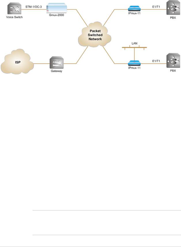
Figure 1-1 illustrates a typical IPmux-11 multiplexing voice and Ethernet traffic over an IP link.
Figure 1-1. Multiplexing Voice and Ethernet over a Packet-Switched Network
E1 Interface
The E1 port complies with G.703, G.704, and G.823 standards. The E1 port supports unframed, framed and multiframed operation with or without CRC-4. The E1 port supports long haul and short haul input signals and can be monitored for alarms and error statistics.
T1 Interface
The T1 port complies with ANSI T1.403, G.703, and G.704 standards. T1 jitter performance is according to G.824 and TR-62411. The T1 port supports unframed, SF, ESF and Robbed Bit signaling. The T1 port supports long haul and short haul input/output signals and can be monitored for alarms and error statistics. FDL and transmit performance monitoring for T1/ESF are also supported.
Ethernet Interface
IPmux-11 is available with three Ethernet ports (two user and one network port). The Ethernet ports work in the following switch modes:
•Transparent
•Tagged
•Untagged
•Double Tagged.
Half-duplex operation in the IPmux-11 network port is not recommended when transmitting small-size packets, because collisions and backoffs cause large delay variation and may exceed the delay variation buffer tolerance at the receiving end, resulting in buffer underflows and errors.
1-2 |
Overview |
IPmux-11 Ver. 2.00 |

Installation and Operation Manual |
Chapter 1 Introduction |
|
|
IP
The data stream coming from the E1 or T1 port is converted into IP packets that are transported over the Fast Ethernet ports, and vice versa.
TDM bytes are encapsulated in a UDP frame that runs over IP and over Ethernet.
The number of TDM bytes in an IP frame is configurable for throughput/delay tradeoff.
Each device has a single IP address (host IP). A configurable destination IP address is assigned to the IP packets. IP ToS field support can be configured for IP level priority.
The Ethernet ports can be either UTP or fiber.
•Fiber option – standard 100BaseFx full-duplex port (see Table 1-1).
•UTP option – A standard 10/100BaseT half/full duplex port with autonegotiation and automatic crossover support. If autonegotiation is disabled, Ethernet mode should be configured.
Table 1-1. Fiber Optic Interface Options
Wavelength |
Fiber Type |
Transmitter |
|
Power |
|
Receiver |
Loss |
|
Budget |
|
|
|
Type |
|
|
|
|
Sensitivity |
|
|
[dBm] |
[nm] |
[μm] |
|
|
[dBm] |
|
[dBm] |
|
|
||
|
|
|
[dB/km] |
|
||||||
|
|
|
|
|
|
|
|
|
|
|
|
|
|
|
Min |
|
Max |
|
Min |
Max |
|
|
|
|
|
|
|
|
|
|
|
|
1310 |
62.5/125 |
LED |
-19 |
|
-14 |
-32 |
1 |
4 |
10* |
|
|
multimode |
|
|
|
|
|
|
|
|
|
|
|
|
|
|
|
|
|
|
|
|
1310 |
9/125 single |
Laser |
-15 |
|
-7 |
-34 |
0.5 |
0.8 |
16* |
|
|
mode |
|
|
|
|
|
|
|
|
|
|
|
|
|
|
|
|
|
|
|
|
*Permitted fiber optic cable length differs according to fiber characteristics, splices, and connectors.
To calculate optical budget:
Optical Budget [dB] =
Receive Sensitivity – Optical Power –3 (Aging) – Connectors/Patch Panels Loss
To calculate distance:
Distance = Optical Budget/Maximum Loss
MPLS
IPmux-11 encapsulates TDM data with MPLS labels for transporting it over MPLS networks (TDMoMPLS). Saving up to 24 bytes of overhead in comparison to the standard TDMoIP encapsulation, TDMoMPLS is ideal for bandwidth-sensitive networks.
TDMoIP Operation Modes
E1/T1 operation modes are:
•Unframed E1/T1 over UDP over IP over Ethernet
•Fractional E1/T1 over UDP over IP over Ethernet
•Fractional E1/T1 with CAS over UDP over IP over Ethernet.
IPmux-11 Ver. 2.00 |
Overview |
1-3 |

Chapter 1 Introduction |
Installation and Operation Manual |
|
|
QoS
QoS supports:
•Labeling IP level priority (ToS/Diffserv) for TDMoIP packets
•VLAN tagging and priority labeling according to IEEE 802.1p&Q for TDMoIP packets
•QoS marking of the TDMoIP traffic in MPLS networks.
The user can configure the ToS (Type of Service) of the outgoing TDMoIP packets. This allows an en-route Layer 3 router or switch, which supports ToS, to give higher priority to IPmux-11 TDMoIP traffic for delay-sensitive and secure applications. IPmux-11 allows you to configure the WHOLE ToS byte field, since different vendors may use different bits to tag packets for traffic prioritization. This also enables operation according to various RFC definitions (for example RFC
2474, RFC 791). The user can also configure VLAN priority bits for Level 2 Priority.
Management
IPmux-11 can be managed locally by connecting an ASCII terminal to the RS-232 port on the rear panel, or via an HTTP connection (Web-based management tool, ConfiguRAD), Telnet or SNMP. The SNMP management capability enables fully graphical, user-friendly management using the RADview Service Center TDMoIP network management stations offered by RAD, as well as management by other SNMP-based management systems.
ConfiguRAD
ConfiguRAD is user-friendly, Web-based terminal management system for remote device configuration and maintenance. It is embedded into IPmux-11 and provided at no extra cost. ConfiguRAD can be run from any standard Web browser.
Timing
IPmux-11 maintains synchronization between TDM devices by deploying advanced clock distribution mechanisms.
Available timing modes are:
•Loopback
•Adaptive
•Internal clock
•External clock.
System clock ensures clock resilience by using master and fallback timing sources for clock redundancy.
IPmux-11 also provides system clock output via external clock connector.
1-4 |
Overview |
IPmux-11 Ver. 2.00 |

Installation and Operation Manual |
Chapter 1 Introduction |
|
|
|
|
|
|
|
|
|
|
1.2 Physical Description
IPmux-11 is a compact easy-to-install standalone unit. Figure 1-2 shows a 3-dimensional view of IPmux-11.
Figure 1-2. IPmux-11 3D View
The front panel includes the IPmux-11 LEDs. For the detailed LED description, see
Chapter 3.
User, network, external clock and management ports, and power supply connector are located on the rear panel of unit. For further details, see Chapter 2.
1.3 Functional Description
IPmux-11 provides TDM connectivity across the IP/Ethernet network. A single bundle (group of timeslots) can be transmitted to a predefined far-end bundle. IPmux-11 supports ICMP (ping), and generates ARP in case of unknown next hop MAC addresses, answers ARP requests, and supports the 802.3 VLAN Ethernet format.
IPmux-11 includes E1 or T1 port. Traffic is transmitted over the network as E1/T1 or fractional E1/T1, using the TDMoIP or TDMoMPLS method.
IPmux-11 supports two Ethernet user ports for user LAN connectivity.
Configuration and management are provided via the IPmux-11 local terminal, Web-based management utility, Telnet or RADview management tool (SNMP).
Operation Modes
This section describes the IPmux-11 operation modes, which are:
•Unframed E1/T1
•Fractional E1/T1
•Fractional E1/T1 with CAS.
IPmux-11 Ver. 2.00 |
Functional Description |
1-5 |

Chapter 1 Introduction |
Installation and Operation Manual |
|
|
Unframed
In the unframed mode, the incoming bit stream from each channel (regardless of framing) is converted into IP over Ethernet frames. This option provides clear channel end-to-end service (unframed).
Fractional
In the fractional mode, the incoming bit stream is regarded as a sequence of
N × 64 kbps timeslots (according to framing). Each predefined group of timeslots is converted into a structure block. The structure block is packetized into IP frames and transmitted.
This mode allows transmission of several selected timeslots without the whole E1 or T1 frame, as in transparent mode.
Fractional with CAS
In the fractional-with-CAS mode, the structure block (as described under Fractional Operation Modes, above) also includes Channel Associated Signaling (CAS) from timeslot 16 (E1) or robbed bit (T1). The relevant portion of the signaling channel is packetized and sent to the destination.
Timeslot Assignment in a Bundle
A bundle is a group of timeslots associated with a specific E1 or T1 channel. IPmux-11 places individual or multiple TDM timeslots (up to 31 timeslots for E1 or up to 24 for T1) into bundles with a single IP address destination.
Testing
Diagnostic capabilities include E1/T1 local and remote loopback tests for rapid localization of faults. The E1/T1 traffic can be looped locally, toward the line, or toward the remote end (see Chapter 6 for more information).
Timing Modes
The E1/T1 Tx clock can operate in several timing modes to provide maximum flexibility for connecting the IPmux-11 E1 or T1 channels.
Each of the clocks must be configured correctly on both the receive and transmit ends to ensure proper operation and prevent slips (see Figure 1-3, Figure 1-4 and
Figure 1-5).
The E1/T1 available Tx modes are:
•Loopback timing – the E1/T1 Tx clock is derived from the E1/T1 receive (Rx) clock.
•Adaptive timing – in this mode, the E1 or T1 Tx clock is regenerated using the adaptive method. In this method, the fill level of the buffer receiving packets is monitored. If the buffer begins to overfill, the regenerated Tx clock frequency increases to avoid overflow. If the buffer begins to empty, the Tx clock frequency (toward the TDM device) decreases to avoid underflow.
1-6 |
Functional Description |
IPmux-11 Ver. 2.00 |
Installation and Operation Manual |
Chapter 1 Introduction |
|
|
•Internal timing – in this mode, the Tx clock is derived from an internal oscillator.
•External timing – in this mode the Tx clock is derived from the external clock input. The external clock port also outputs the input clock signal to allow connection to other units, if needed.
Note In adaptive timing the regenerated clock is subject to network packet delay variation. That is why the quality of the adaptive clock depends on the quality of the network.
Network Timing Schemes
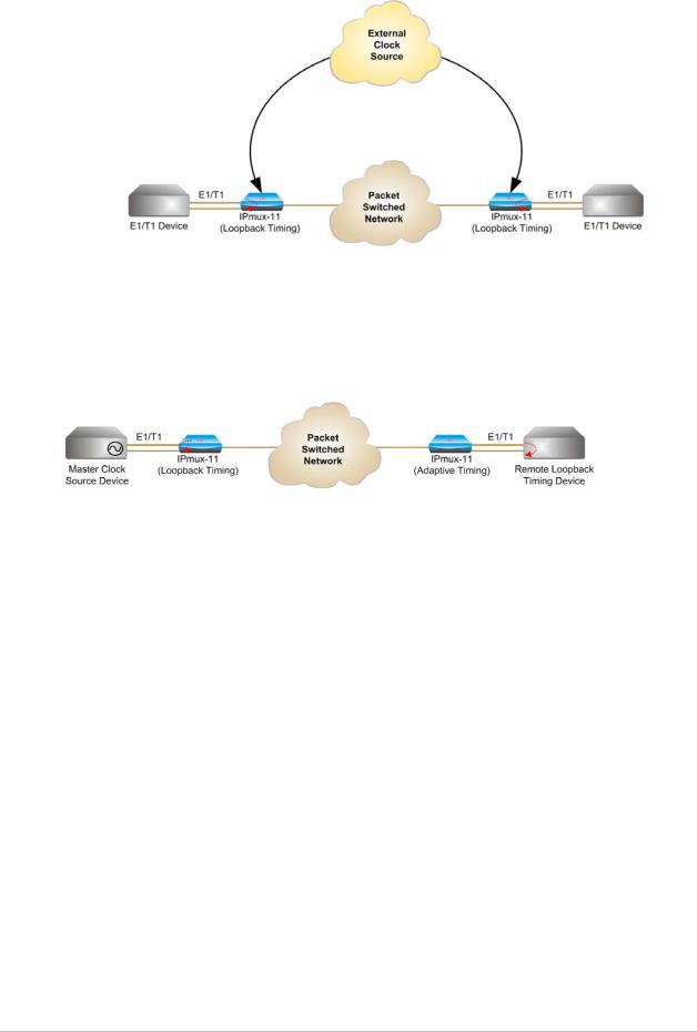
The following paragraphs describe typical timing schemes and the correct timing mode settings for achieving end-to-end synchronization.
External Network Timing
When the edges of the network are synchronized by an external network clock source, all the IPmux-11 units should be configured to work in loopback timing mode (see Figure 1-3). This topology enables any-to-any connectivity.
Figure 1-3. IPmux-11 in Loopback Timing Mode
External timing from the network can also be issued to IPmux-11 by external clock input.
IPmux-11 Ver. 2.00 |
Functional Description |
1-7 |
Chapter 1 Introduction |
Installation and Operation Manual |
|
|
Figure 1-4. IPmux-11 in External Clock Mode
Single Source Clock Network
When a common clock is not available on all the ends of the network, one of the IPmux-11 devices is configured to work in loopback timing, while the other IPmux-11device is configured to work in adaptive timing (see Figure 1-5).
Figure 1-5. IPmux-11 in Adaptive Timing Mode
Frame Format
TDMoIP
The Ethernet frame sent by IPmux-11 is a UDP datagram that transfers E1/T1 payload bytes over IP over Ethernet (UDP payload + UDP header + IP header + Ethernet header). The UDP payload is equal to TDM bytes per frame
(TDM bytes/frame configuration). Table 1-2 specifies the structure of the different headers, special fields, and the payload in the Ethernet packet.
CRC |
TDM Payload |
CW |
UDP |
IP |
ETH |
|
|
|
|
|
|
Figure 1-6. TDMoIP Frame Structure
1-8 |
Functional Description |
IPmux-11 Ver. 2.00 |

Installation and Operation Manual |
Chapter 1 Introduction |
|
|
ETH
Layer
LLC
Layer
IP Layer
UDP
Layer
Table 1-2. TDMoIP Frame Structure
Field Length (Bytes) |
Field |
|
|
7 |
Preamble |
|
|
1 |
SFD |
|
|
6 |
Destination MAC Address |
|
|
6 |
Source MAC Address |
|
|
2 |
Type |
|
|
1 |
Vers/HLEN |
|
|
1 |
Service Type |
|
|
2 |
Total Length |
|
|
2 |
Identification |
|
|
1 |
Flags/Fragment Offset (most) |
|
|
1 |
Fragment Offset (least) |
|
|
1 |
Time to Live |
|
|
1 |
Protocol |
|
|
2 |
Header Checksum |
|
|
4 |
Source IP Address |
|
|
4 |
Destination IP Address |
|
|
2 |
UDP Source Port |
|
|
2 |
UDP Destination Port |
|
|
2 |
UDP Message Length |
|
|
2 |
UDP Checksum |
Note: IEEE 802.1p&Q VLAN Tagging (additional 4 bytes if enabled)
The UDP source port field is used to transfer a destination bundle number. See Note below.
Data
Layer
ETH
Layer
... Payload
4 |
CRC |
|
|
The UDP Source Port value calculation depends on the selected TDMoIP version
(1 or 2):
Note
•TDMoIP version 2: The UDP Source Port value equals 0x2000 + Destination Bundle Number, it is always greater than 8192.
•TDMoIP version 1:
During normal operation the UDP Source Port value equals Destination Bundle Number + 1 (for example, for bundle 1 the UDP Source Port equals 2). The allowed range for the UDP Source Port values in the normal state is from 0 to 8191.
If a bundle is in the local fail state, the MSB of the UDP Source Port is set to 1 to indicate the local fail state to the remote equipment. In this case the UDP Source Port value equals 0x8000 + Destination Bundle Number + 1.
The UDP Source Port value in the local fail state is always greater than 32768.
IPmux-11 Ver. 2.00 |
Functional Description |
1-9 |

Chapter 1 Introduction |
Installation and Operation Manual |
|
|
VLAN Support
VLAN, according to IEEE 802.1p&Q, adds four bytes to the MAC layer of the Ethernet frame. The user can set the contents of these bytes, MAC layer priority and VLAN ID. In this mode, only VLAN format frames are sent and received by IPmux-11. Figure 1-7 shows the VLAN tag format.
81 |
00 |
|
|
802.1D Tag Protocol Type
user_priority |
0 |
|
|
|
VID |
|
|
|
CFI = |
|
|
|
|
8 |
6 |
5 |
4 |
1 |
8 |
1 |
|
Priority |
|
|
|
|
VLAN ID |
Figure 1-7. VLAN Tag Format (802.1p&Q)
UDP Support
Table 1-3. UDP Ports Definition
Field Length (Bits) |
Field Description |
Value |
Function |
|
|
|
|
2 bytes |
UDP Source Port |
2–497d* |
Destination timeslots bundle |
|
|
|
|
2 bytes |
UDP Destination Port |
2142d |
Standard TDMoIP UDP port |
|
|
|
|
* The MSB of this field can be either 1 or 0 for inband end-to-end proprietary signaling.
Note The UDP Source Port field is used for destination timeslots bundle indication.
For more information about VLAN tagging, refer to IEEE standard 802.1p&Q.
TDMoMPLS
Figure 1-9 and Table 1-4 illustrate TDMoMPLS frame structure.
CRC |
TDM Payload |
CW |
MPLS |
ETH |
|
|
|
|
|
Figure 1-8. TDMoMPLS Frame Structure
1-10 |
Functional Description |
IPmux-11 Ver. 2.00 |

Installation and Operation Manual |
Chapter 1 Introduction |
|
|
Table 1-4. TDMoMPLS Frame Structure
|
Field Length (Bytes) |
Field |
|
|
7 |
Preamble |
|
ETH |
1 |
SFD |
|
6 |
Destination MAC Address |
||
Layer |
|||
|
6 |
Source MAC Address |
|
LLC |
2 |
Type |
|
Layer |
20 |
Outer label |
|
|
3 |
EXP |
|
|
1 |
Stacking bit |
|
MPLS |
8 |
TTL |
|
Layer |
20 |
Inner label |
|
|
3 |
EXP |
|
|
1 |
Stacking bit |
|
Data |
8 |
TTL |
|
Layer ... |
Payload |
||
|
|
||
ETH |
4 |
CRC |
|
Layer |
|||
Packet Delay Variation
Note: IEEE 802.1p&Q VLAN Tagging (additional 4 bytes if enabled)
The inner label field is used to transfer a destination bundle number.
Packets are transmitted at set intervals. Packet Delay Variation is the maximum deviation from the nominal time the packets are expected to arrive at the far end device. IPmux-11 has a buffer that compensates for the deviation from the expected packet arrival time to prevent IPmux-11 buffers from emptying out or overflowing.
Packet Delay Variation is an important network parameter. Large PDV (exceeding the jitter buffer configuration) will cause receive buffer underflows and errors at the TDM level (see Figure 1-9).
To compensate for large PDV, configure the PDVT (jitter) buffer to a higher value.
Packets Leaving IPmux-11 t
t
Packets Arriving  t
t
PDV
Figure 1-9. Packet Delay Variation
IPmux-11 Ver. 2.00 |
Functional Description |
1-11 |

Chapter 1 Introduction |
Installation and Operation Manual |
|
|
PDVT (Jitter) Buffer
IPmux-11 is equipped with a Packet DVT (Delay Variation Tolerance) buffer. The PDVT buffer or jitter buffer is filled by the incoming IP packets and emptied out to fill the TDM stream. The buffer begins to empty out only after it is half full in order to compensate for packet starvation from the Ethernet side. The time it takes for half of the buffer to empty out is the maximum DVT time. The PDVT (jitter) buffer is designed to compensate for packet delay variation caused by the network + packetization delay. It supports a delay variation of up to 300 ms for E1 or T1.
|
PDVT Buffer Effect on Delay |
|||
|
The PDVT buffer is on the TDM path; it adds to the total end-to-end delay (see |
|||
|
delay calculation, below). |
|||
|
Packetization Delay |
|||
|
When IPmux-11 builds a frame, a packetization delay is introduced. The |
|||
|
packetization delay is calculated according to the following formula: |
|||
|
Packetization delay (ms) = 47 ×N ×0.125 |
|||
|
|
|
TS |
|
|
Where: |
|||
|
N = |
TDM bytes/frame |
|
|
|
48 |
|
||
|
TS = number of assigned timeslots (in unframed mode= 32 for E1, 24 for T1) |
|||
|
Jitter Buffer Depth |
|||
|
The jitter buffer depth is configured according to the following formula: |
|||
|
Jitter buffer = PDV introduced by the network (measured or estimated) + |
|||
|
packetization delay. |
|||
Note |
|
|
|
|
For a bundle that contains a few timeslots (i.e. 1 to 3,) the recommended number |
||||
|
||||
|
of TDM bytes/frame is 48 in order to prevent excessive packetization delay. |
|||
|
|
|
|
|
Ethernet Throughput
Increasing payload size reduces the ratio of the TDMoIP header segment in the packet, thus reducing the total Ethernet throughput.
Increased payload reduces the IP/Ethernet overhead segment of the total packet and thus can reduce the total Ethernet throughput.
On the other hand, packetization delay is increased; this contributes to a higher end-to-end delay. This effect can be small and negligible when a full E1 (or many timeslots) are transferred, but can be very significant when few timeslots are transferred. In this case, when configuring a large value of TDM bytes/frame, the packetization delay can be very large and may exceed the maximum PDVT (jitter) buffer on the receiving end.
1-12 |
Functional Description |
IPmux-11 Ver. 2.00 |

Installation and Operation Manual |
Chapter 1 Introduction |
|
|
Configuring the TDM bytes per frame (TDM bytes/frame) parameter has impact on the Ethernet throughput (bandwidth or traffic traveling through the Ethernet). This parameter controls the number of TDM bytes encapsulated in one frame.
The TDM bytes/frame parameter can be configured to N × 48 bytes where N is an integer between 1 and 30.
To calculate Ethernet throughput as a function of TDM bytes/frame:
Ethernet load (bps) = [(frame overhead (bytes) + TDM bytes/frame) × 8] × frames/second
Frame overhead = Ethernet overhead + IP overhead = 46 bytes
Note The frame overhead does not include:
•Preamble field: 7 bytes
•SFD field: 1 byte
•Interframe gap: 12 bytes
•VLAN field (when used): 4 bytes.
Frame/second =
Unframed: 5447/n for a full E1 4107/n for a full T1
Framed: 8000 × k/(46.875 x n) Where k = number of assigned timeslots
Where n = TDM bytes/frame 48
The maximum Ethernet throughput mode is calculated by:
Unframed
|
|
data |
|
|
|
|
64748 |
|
|
|
|
8000 * TS |
* 8 bits |
|
(VLAN + frame overhead +payload) * |
47 * n |
|
||
1444444244444443 |
|
|
|
|
frame size |
|
|
|
|
|
|
|
|
|
Framed
|
|
data |
pointer |
CAS |
|
|
|
|
|
64748 |
64748 |
|
|
||
|
|
64748 |
8000 * TS |
TS |
|
|
|
|
8000 * TS + |
(47 * 8) - 1 |
+500 * |
|
|
||
|
|
|
2 |
|
|
|
|
(VLAN + frame overhead +payload) * |
|
|
|
|
|
* 8 bits |
|
|
47 * n |
|
|
||||
1444444244444443 |
|
|
|
|
|
|
|
frame size |
|
|
|
|
|
|
|
|
|
|
|
|
|
|
|
|
|
|
|
|
|
|
|
IPmux-11 Ver. 2.00 |
Functional Description |
1-13 |

Chapter 1 Introduction |
Installation and Operation Manual |
|
|
Where:
•VLAN is an optional field: if enabled it adds 4 bytes to the frame overhead
•payload = number of TDM bytes in frame, (48, 96, 144, 192, … 1440)
•frame overhead = size of 46 bytes, include MAC, LLC, IP and UDP layer
•CAS is signaling (framed mode only)
•TS is number of assigned timeslots.
The result in both the equations is in bits per second (bps).
Round Trip Delay
The voice path round-trip delay is a function of all connections and network parameters.
47 ×N
(±2 msec) RTDelay(msec) = 2 × [ NTS × 0.125 msec + PDVT buffer msec +1 msec] + network round trip delay
Where
N = TDMbytes/frame 48
NTS = number of assigned timeslots (in unframed mode= 32 for E1, 24 for T1)
Reorder and Duplication of Ethernet Frames
IPmux-11 handles situations in the IP network where:
•Packets are reordered by the network
•Packets are duplicated.
Reordering Frames
The ability to correct problems of reordering depends on the selected payload (TDMoIP) format: version 1 (V1) or version 2 (V2).
Frame reordering is supported for odd values of payload, i.e. 1, 3, 5, 7, …, 29 in V1 mode or for any payload in V2 mode.
You can reorder up to seven frames for V1 and up to 64 frames for V2; the number depends on the number of TDM bytes/frame size and buffer size.
The number of frames that can be reordered is calculated by: (Jitter Buffer[msec] −1)(Ts ×8)
47 ×Payload
Where:
•Ts = number of timeslots
•Payload = number of TDM bytes in frame, i.e. 1, 3, 5, 7, …, 29 for V1 or 1, 2, 3, …, 29 for V2.
1-14 |
Functional Description |
IPmux-11 Ver. 2.00 |
Installation and Operation Manual |
Chapter 1 Introduction |
|
|
Note For V1 the maximum number of frames that can be reordered is 7, even if the calculation result exceeds 7. For V2 the maximum number of frames that can be reordered is 64, even if the calculation result exceeds 64.
Duplicated Frames
When frames are duplicated, IPmux-11 only uses the later frame.
OAM Connectivity
When a destination IPmux-11 is lost, the traffic load that is transmitted to that IPmux is significantly decreased (several packets per second per connection). The IPmux starts transmitting at full rate only when it detects an IPmux at the remote side.
OAM connectivity is used to detect a valid connection (the remote IPmux will confirm it recognizes the connection and that it is enabled). It prevents flooding by a handshake.
The control packets are run over a unique bundle number that is used for this purpose. The control packets have the same VLAN ID and TOS of the originating connection. The control packet uses the TDMoIP UDP number.
OAM connectivity can be set to Disable/Enable.
Note For control packets, the UDP checksum is not calculated nor checked.
End-to-End Alarm Generation
An end-to-end alarm generation mechanism exists in IPmux-11 to facilitate the following alarms:
•Unframed – AIS is transmitted toward the near-end PBX in event of: Far-end LOS, AIS
PDVT underflow/overflow.
•Framed – Timeslot/CAS configurable alarm pattern is transmitted toward the near-end PBX in event of:
Far-end LOS, LOF, AIS
PDVT underflow/overflow.
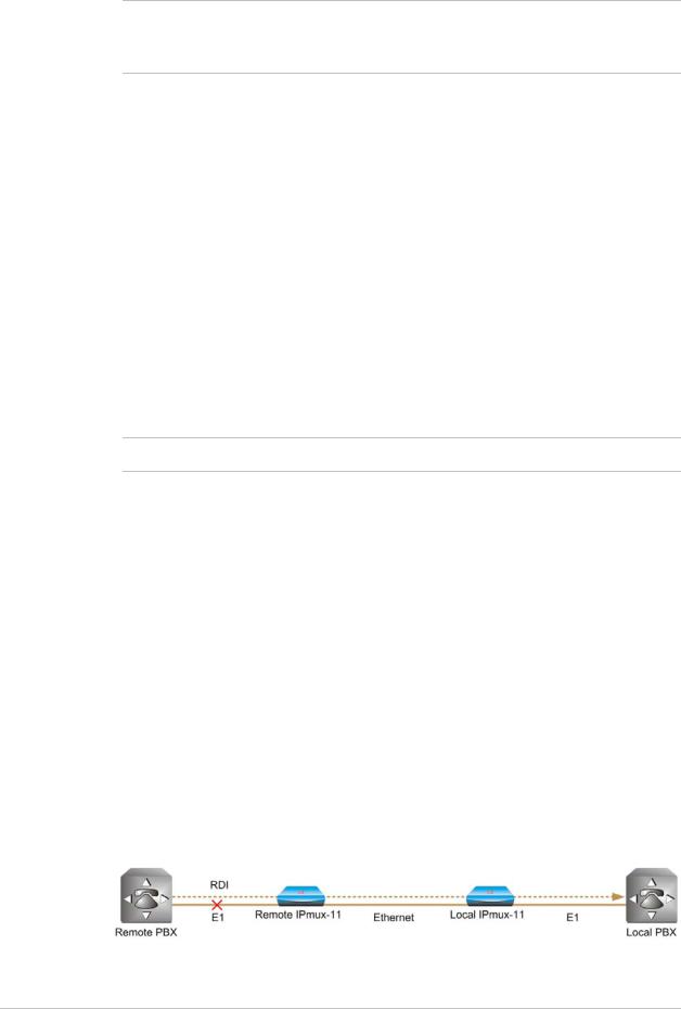
Trail-Extended Mode
To enhance fault condition reporting capabilities, remote IPmux-11 transfers RDI, LOS and AIS conditions received from the remote E1 device to the local E1 device (see Figure 1-10).
Figure 1-10. Fault Indication Transfer
IPmux-11 Ver. 2.00 |
Functional Description |
1-15 |

Chapter 1 Introduction |
Installation and Operation Manual |
|
|
IPmux-11 transfers fault conditions only if the payload format is configured to V2. The fault conditions are transferred as follows:
•Framed E1 or T1: RDI as RDI, LOS and AIS as AIS
•Unframed E1 or T1: LOS and AIS as AIS.
VLAN Traffic Behavior
Table 1-5 lists the IP and VLAN validity checks that are performed with each
Ethernet packet that is received by IPmux-11.
Table 1-5. VLAN Check for Packets that are Received by IPmux-11
Packet Type |
Source IP Check |
VLAN Check |
|
|
|
|
|
|
|
Management |
Performed |
Performed |
|
|
|
|
|
|
|
TDM over IP |
Performed |
Performed |
|
|
|
|
|
|
|
Receiving ping |
Not performed |
Not performed, even if it is one of |
|
|
|
|
|
the IPs that is configured for the |
|
ARP |
Not performed |
|
||
manager or for the connection |
|
|||
|
|
|
|
|
|
|
|
|
|
Telnet |
Performed only when Telnet access mark is |
Performed only when Telnet access |
|
|
|
from manager |
mark is from manager |
|
|
|
|
|
||
|
Table 1-6 lists the IP and VLAN validity checks that are performed with each |
|
||
|
Ethernet packet that is sent by IPmux-11. |
|
|
|
|
|
Table 1-6. VLAN Check for Packets Sent by IPmux-11 |
|
|
|
|
|
|
|
Packet Type |
|
VLAN Support |
|
|
|
|
|
|
|
Management |
|
As configured for the manager |
|
|
|
|
|
|
|
TDM over IP |
|
As configured for the connection |
|
|
|
|
|
|
|
Answer to ping |
|
Packet with VLAN tagging: IPmux-11 replies with the same VLAN ID (even |
|
|
|
|
if it is s one of IPs configured for the manager or for the connection). |
|
|
|
|
Packet without VLAN tagging: if it is one of the IPs configured for the |
|
|
|
|
manager or for the connection, the IPmux-11 replies with the VLAN ID |
|
|
|
|
that is in the manager or connection configuration. |
|
|
|
|
|
||
ARP initiated by IPmux-11 |
No VLAN value unless it is to one of the managers or the connection’s IP |
|
||
Telnet |
|
address |
|
|
|
|
|
|
|
Ping initiated by IPmux-11
Ethernet Ports
The Ethernet user ports allow a user to aggregate both TDMoIP traffic and his private network LAN traffic to a single Ethernet network connection without requiring an access switch. This is a cost-effective solution for MTU or small-office applications. A rate limiter to restrict user port traffic is supported.
IPmux-11 contains an internal bridge where one of its ports is connected to a TDMoIP interworking function, two external bridge ports is used as the user ports, and the fourth is used as an Ethernet network port.
1-16 |
Functional Description |
IPmux-11 Ver. 2.00 |
Loading...