


 Loading...
IPmux-1, IPmux-1E
TDMoIP Gateways
Installation and Operation Manual
Notice
This manual contains information that is proprietary to RAD Data Communications. No part of this publication may be reproduced in any form whatsoever without prior written approval by RAD Data Communications.
No representation or warranties for fitness for any purpose other than what is specifically mentioned in this manual is made either by RAD Data Communications or its agents.
For further information contact RAD Data Communications at the address below or contact your local distributor.
|
International Headquarters |
U.S. Headquarters |
|
|
RAD Data Communications Ltd. |
RAD Data Communications Inc. |
|
|
24 Raoul Wallenberg St. |
900 Corporate Drive |
|
|
Tel Aviv 69719 Israel |
Mahwah, NJ 07430 USA |
|
|
Tel: 972-3-6458181 |
Tel: (201) 529-1100 |
|
|
Fax: 972-3-6498250 |
Toll free: 1-800-444-7234 |
|
|
E-mail: rad@rad.co.il |
Fax: (201) 529-5777 |
|
|
|
E-mail: market@radusa.com |
|
© 2001 RAD Data Communications |
Publication No. 114-200-09/01 |
||
Order from: Cutter Networks |
Ph:727-398-5252/Fax:727-397-9610 |
www.bestdatasource.com |
Warranty
This RAD product is warranted against defects in material and workmanship for a period of one year from date of shipment. During the warranty period, RAD will, at its option, either repair or replace products which prove to be defective. For warranty service or repair, this product must be returned to a service facility designated by RAD. Buyer shall prepay shipping charges to RAD and RAD shall pay shipping charges to return the product to Buyer. However, Buyer shall pay all shipping charges, duties and taxes for products returned to RAD from another country.
Limitation of Warranty
The foregoing warranty shall not apply to defects resulting from improper or inadequate maintenance by Buyer, Buyer-supplied firmware or interfacing, unauthorized modification or misuse, operation outside of the environmental specifications for the product, or improper site preparation or maintenance.
Exclusive Remedies
The remedies provided herein are the Buyer’s sole and exclusive remedies. RAD shall not be liable for any direct, indirect special, incidental, or consequential damages, whether based on contract, tort, or any legal theory.
Regulatory Information
FCC-15 User Information
This equipment has been tested and found to comply with the limits of the Class B digital device, pursuant to Part 15 of the FCC rules. These limits are designed to provide reasonable protection against harmful interference when the equipment is operated in a commercial environment. This equipment generates, uses and can radiate radio frequency energy and, if not installed and used in accordance with the instruction manual, may cause harmful interference to the radio communications. Operation of this equipment in a residential area is likely to cause harmful interference in which case the user will be required to correct the interference at his own expense.
Order from: Cutter Networks |
Ph:727-398-5252/Fax:727-397-9610 |
www.bestdatasource.com |

Safety Warnings
The exclamation point within a triangle is intended to warn the operator or service personnel of operation and maintenance factors relating to the product and its operating environment which could pose a safety hazard.
Always observe standard safety precautions during installation, operation and maintenance of this product. Only a qualified and authorized service personnel should carry out adjustment, maintenance or repairs to this instrument. No adjustment, maintenance or repairs should be performed by either the operator or the user.
Telecommunication Safety
The safety status of each of the ports on IPmux-1/1E is declared according to EN 41003 and is detailed in the table below:
Safety Status |
Ports |
SELV |
LAN, Unbalanced E1, E&M, ISDN-S |
|
|
TNV-1 |
Balanced E1, T1 |
|
|
TNV-2 |
FXS |
|
|
TNV-3 |
FXO |
SELV = Safety Extra-Low Voltage
TNV-1 = Telecommunications Network Voltage within the limits of SELV and subject to overvoltages
TNV-2 = Telecommunications Network Voltage not subject to overvoltages
TNV-3 = Telecommunications Network Voltage subject to overvoltages
Order from: Cutter Networks |
Ph:727-398-5252/Fax:727-397-9610 |
www.bestdatasource.com |

Declaration of Conformity
Manufacturer’s Name: |
|
RAD Data Communications Ltd. |
|
Manufacturer’s Address: |
24 Raoul Wallenberg St. |
||
|
|
|
Tel Aviv 69719 |
|
|
|
Israel |
declares that the product: |
|
||
Product Name: |
IPmux-1 |
||
conforms to the following standard(s) or other normative document(s): |
|||
EMC: |
EN 55022 (1998) |
Information technology equipment – Radio disturbance |
|
|
characteristics – Limits and methods of measurement. |
||
|
EN 50024 (1998) |
Information technology equipment –Immunity |
|
|
characteristics – Limits and methods of measurement. |
||
Safety: |
EN 60950/A4 (1996)Safety of information technology equipment, including electrical |
||
|
business equipment. |
||
Supplementary Information:
The product herewith complies with the requirements of the EMC Directive 89/336/EEC and the
Low Voltage Directive 73/23/EEC. The product was tested in a typical configuration.
Tel Aviv, March 18th, 2001
Haim Karshen
VP Quality
European Contact: RAD Data Communications GmbH, Berner Strasse 77, 60437 Frankfurt am Main, Germany
Order from: Cutter Networks |
Ph:727-398-5252/Fax:727-397-9610 |
www.bestdatasource.com |
|
|
Contents |
|
|
|
Chapter 1. Introduction |
|
|
|
1.1 |
Overview .......................................................................................................... |
1-1 |
|
|
|
|
Versions................................................................................................................... |
1-1 |
|
|
|
Applications............................................................................................................. |
1-2 |
|
|
|
Features................................................................................................................... |
1-6 |
|
1.2 |
Physical Description........................................................................................ |
1-10 |
|
|
|
|
Front Panel ............................................................................................................ |
1-11 |
|
|
|
Rear Panel ............................................................................................................. |
1-11 |
|
1.3 |
Functional Description .................................................................................... |
1-11 |
|
|
|
|
Operation Modes .................................................................................................. |
1-12 |
|
|
|
BRI/FXS TS Assignment in a Bundle ........................................................................ |
1-14 |
|
|
|
Testing................................................................................................................... |
1-14 |
|
|
|
Timing Modes........................................................................................................ |
1-15 |
|
|
|
Network Timing Schemes ...................................................................................... |
1-16 |
|
|
|
Frame Format ........................................................................................................ |
1-17 |
|
|
|
Packet Delay Variation........................................................................................... |
1-19 |
|
|
|
PDVT (Jitter) Buffer ................................................................................................ |
1-20 |
|
|
|
Ethernet Throughput.............................................................................................. |
1-20 |
|
|
|
Round Trip Delay .................................................................................................. |
1-22 |
|
|
|
Ethernet User Port ................................................................................................. |
1-23 |
|
1.4 |
Technical Specifications .................................................................................. |
1-24 |
|
|
|
Chapter 2. Installation |
|
|
|
2.1 |
Introduction...................................................................................................... |
2-1 |
|
|
2.2 |
Site Requirements and Prerequisites.................................................................. |
2-1 |
|
|
2.3 |
Package Contents.............................................................................................. |
2-2 |
|
|
|
|
Power Cable............................................................................................................ |
2-2 |
|
2.4 |
Equipment Needed........................................................................................... |
2-2 |
|
|
2.5 |
Installation and Setup........................................................................................ |
2-2 |
|
|
|
|
Setting Jumpers........................................................................................................ |
2-2 |
|
|
|
Connecting Interfaces and Cables............................................................................. |
2-4 |
|
|
|
Connecting the Power ............................................................................................. |
2-9 |
|
|
Chapter 3. Operation |
|
|
|
3.1 |
Front Panel Controls, Connectors, and Indicators .............................................. |
3-1 |
|
|
3.2 |
Operating Instructions....................................................................................... |
3-4 |
|
|
|
|
Turning IPmux-1/1E On ........................................................................................... |
3-4 |
|
|
|
Login ....................................................................................................................... |
3-5 |
|
|
|
Turning IPmux-1/1E Off ........................................................................................... |
3-5 |
|
3.3 |
Getting Started.................................................................................................. |
3-6 |
|
|
3.4 |
Overview of Menu Operations.......................................................................... |
3-6 |
|
|
|
|
Navigating ............................................................................................................... |
3-6 |
|
|
|
Main Menu............................................................................................................ |
3-10 |
|
|
|
System Menu......................................................................................................... |
3-10 |
|
|
|
|
|
|
|
IPmux-1/1E Installation and Operation Manual |
i |
||
Order from: Cutter Networks |
Ph:727-398-5252/Fax:727-397-9610 |
www.bestdatasource.com |
||

Table of Contents
|
Setting IPmux-1/1E Configuration Options.............................................................. |
3-11 |
|
Performance Monitoring ........................................................................................ |
3-13 |
Chapter 4. Troubleshooting and Diagnostics |
|
|
4.1 |
Error Detection ................................................................................................. |
4-1 |
|
Using Front Panel LEDs............................................................................................ |
4-1 |
|
Working with the Alarm Buffer................................................................................. |
4-1 |
4.2 |
Troubleshooting ................................................................................................ |
4-3 |
4.3 |
Diagnostic Tests ................................................................................................ |
4-3 |
|
E1/T1....................................................................................................................... |
4-3 |
|
BRI .......................................................................................................................... |
4-4 |
|
FXS.......................................................................................................................... |
4-5 |
Chapter 5. Application Configuration Procedures |
|
|
5.1 |
Overview .......................................................................................................... |
5-1 |
|
Application .............................................................................................................. |
5-1 |
|
Guidelines ............................................................................................................... |
5-2 |
5.2 |
IPmux-1............................................................................................................ |
5-4 |
|
Powering-up............................................................................................................ |
5-4 |
|
Configuring IPmux-1 for Station A ............................................................................ |
5-5 |
|
Configuring IPmux-1 Station B ................................................................................. |
5-8 |
5.3 |
IPmux-4.......................................................................................................... |
5-10 |
|
Powering-up.......................................................................................................... |
5-10 |
|
Configuring IPmux-4.............................................................................................. |
5-11 |
5.4 |
Configuring the Management Option.............................................................. |
5-14 |
5.5 |
Checking the Application ................................................................................ |
5-17 |
|
Using IPmux Statistics – Step 1............................................................................... |
5-17 |
|
Using TDM Equipment Statistics and Functionality – Step 2.................................... |
5-18 |
Appendix A. Boot Sequence for Downloading Software
Appendix B. Telnet
Appendix C. SNMP Management
Appendix D. TFTP Download Procedures
Appendix E. Parameters and Screens
Index
ii |
IPmux-1/1E Installation and Operation Manual |
Order from: Cutter Networks |
Ph:727-398-5252/Fax:727-397-9610 |
www.bestdatasource.com |

Table of Contents
List of Figures
1-1. |
Multiplexing Voice and Data over an Ethernet Trunk................................................. |
1-2 |
|
1-2. |
E1/T1 Circuit Extension over an IP Based Network .................................................... |
1-3 |
|
1-3. |
Mixed BRI and POTS Support Application................................................................. |
1-4 |
|
1-4. |
U Interface Concentration ......................................................................................... |
1-5 |
|
1-5. |
Extending BRI Ports of a Small Office......................................................................... |
1-5 |
|
1-6. |
Ethernet-based Multi-tenant Application with Voice and Data Integrated Access ....... |
1-6 |
|
1-7. IPmux-1 |
3-D View .................................................................................................. |
1-10 |
|
1-8. IPmux-1E 3-D View.................................................................................................. |
1-10 |
||
1-9. |
IPmux-1 |
Functional Diagram ................................................................................... |
1-11 |
1-10. |
Grooming of Timeslots from Remote Sites into a Single E1/T1 Port at Central Site. 1-12 |
||
1-11. |
TS Assignment in a Bundle for IPmux-1E/BRI......................................................... |
1-14 |
|
1-12. IPmux-1 in Loopback Timing Mode....................................................................... |
1-16 |
||
1-13. |
IPmux-1 in External Clock Mode ........................................................................... |
1-16 |
|
1-14. |
IPmux-1 in Adaptive Timing Mode ........................................................................ |
1-17 |
|
1-15. |
IPmux-1E in Adaptive Timing Mode ...................................................................... |
1-17 |
|
1-16. |
TDMoIP Frame Structure....................................................................................... |
1-17 |
|
1-17. VLAN Tag Format (802.1p&q) ............................................................................... |
1-19 |
||
1-18. |
Packet Delay Variation .......................................................................................... |
1-20 |
|
1-19. |
IPmux-1/1E with Ethernet User Port ...................................................................... |
1-23 |
|
2-1. |
The IPmux-1E ISDN-S Jumpers.................................................................................. |
2-4 |
|
2-2. |
IPmux-1 |
Front Panel.................................................................................................. |
2-4 |
2-3. |
IPmux-1 |
Front Panel for Two Ethernet Ports .............................................................. |
2-5 |
2-4. |
IPmux-1 |
Rear Panel................................................................................................... |
2-5 |
2-5. |
IPmux-1 |
Rear Panel for Two Ethernet Ports ............................................................... |
2-5 |
2-6. |
IPmux-1E Front Panel................................................................................................ |
2-5 |
|
2-7. |
IPmux-1E Front Panel for Two Ethernet Ports ............................................................ |
2-5 |
|
2-8. |
IPmux-1E Rear Panel (BRI Option) ............................................................................ |
2-5 |
|
2-9. |
IPmux-1E Rear Panel (BRI Option) for Two Ethernet Ports ......................................... |
2-6 |
|
2-10. |
External Clock Port Pinout....................................................................................... |
2-8 |
|
3-1. |
IPmux-1 |
Front Panel LEDs......................................................................................... |
3-2 |
3-2. |
IPmux-1 |
Rear Panel Switch........................................................................................ |
3-2 |
3-3. |
IPmux-1E Front Panel Indicators................................................................................ |
3-3 |
|
3-4. |
IPmux-1E Back Panel Indicators ................................................................................ |
3-3 |
|
3-5. |
IPmux-1 |
(E1/T1) Terminal Menu Tree........................................................................ |
3-7 |
3-6. IPmux-1E ISDN-S Terminal Menu Tree ..................................................................... |
3-8 |
||
3-7. IPmux-1E FXS Terminal Menu Tree ........................................................................... |
3-9 |
||
3-8. IPmux-1/1E Main Menu .......................................................................................... |
3-10 |
||
3-9. System Menu .......................................................................................................... |
3-11 |
||
3-10. |
IPmux-1/1E Configuration Menu ........................................................................... |
3-11 |
|
3-11. |
IPmux-1E ISDN-S Configuration Menu .................................................................. |
3-11 |
|
3-12. |
IPmux-1E FXS Configuration Menu........................................................................ |
3-12 |
|
3-13. |
Performance Monitoring Menu for IPmux-1 .......................................................... |
3-13 |
|
|
|
||
IPmux-1/1E Installation and Operation Manual |
iii |
||
Order from: Cutter Networks |
Ph:727-398-5252/Fax:727-397-9610 |
www.bestdatasource.com |

Table of Contents
3-14. |
Performance Monitoring Menu for IPmux-1E ISDN-S ............................................ |
3-13 |
3-15. |
Performance Monitoring Menu for IPmux-1E FXS.................................................. |
3-13 |
4-1. |
IPmux-1 External Loop .............................................................................................. |
4-4 |
4-2. |
IPmux-1 Internal Loop............................................................................................... |
4-4 |
4-3. |
IPmux-1E/BRI External Loop...................................................................................... |
4-4 |
4-4. |
IPmux-1E/BRI Internal Loop ...................................................................................... |
4-5 |
5-1. |
IPmux-1 Operating Opposite IPmux-4 ...................................................................... |
5-1 |
5-2. Host IP Menu............................................................................................................ |
5-5 |
|
5-3. |
E1/T1 Configuration Menu ........................................................................................ |
5-6 |
5-4. |
DS0 Bundle Configuration Menu............................................................................... |
5-7 |
5-5. |
Bundle Connection Configuration ............................................................................. |
5-8 |
5-6. |
Physical Layer Configuration Menu.......................................................................... |
5-12 |
5-7. |
Bundle Connection Configuration in IPmux-4 ......................................................... |
5-14 |
5-8. |
Authentication/Community Menu ........................................................................... |
5-15 |
5-9. |
Manager List Menu.................................................................................................. |
5-16 |
5-10. Alarms Trap Mask Menu........................................................................................ |
5-16 |
|
5-11. Default Gateway Menu ......................................................................................... |
5-17 |
|
List of Tables
1-1. |
Fiber Options ............................................................................................................ |
1-8 |
1-2. |
Ethernet Frame Structure......................................................................................... |
1-18 |
1-3. |
UDP Ports Definition............................................................................................... |
1-19 |
1-4. |
Ethernet Throughput – Unframed E1 ....................................................................... |
1-21 |
1-5. |
Ethernet Throughput – Unframed T1....................................................................... |
1-21 |
2-1. |
E1/T1 Port Connectors Pinout.................................................................................... |
2-7 |
2-2. |
Ethernet Port Pinout .................................................................................................. |
2-7 |
2-3. |
Control Port Pinout ................................................................................................... |
2-7 |
2-4. |
ISDN-S Interface Pin Assignments.............................................................................. |
2-8 |
2-5. |
FXS Interface Pin Assignments for RJ-11..................................................................... |
2-8 |
2-6. |
External Clock Port Pinout......................................................................................... |
2-8 |
3-1. |
IPmux-1 System Indicators and Switches ................................................................... |
3-2 |
3-2. |
IPmux-1E (BRI/FXS) System Indicators and Switches .................................................. |
3-3 |
4-1. |
Event Types............................................................................................................... |
4-2 |
4-2. |
IPmux-1 Troubleshooting Chart................................................................................. |
4-3 |
5-1. |
Bundle Configuration ................................................................................................ |
5-3 |
5-2. |
Configuration Summary............................................................................................. |
5-3 |
iv |
IPmux-1/1E Installation and Operation Manual |
Order from: Cutter Networks |
Ph:727-398-5252/Fax:727-397-9610 |
www.bestdatasource.com |

Chapter 1
Introduction
1.1 Overview
IPmux-1/1E offers a solution for extending traditional E1/T1, ISDN, or POTS TDM services transparently over the widely deployed IP networks. The device converts the data stream coming from its user ports into configurable sized IP packets that are extended over the Fast Ethernet port and vice versa. IPmux-1/1E offers end-to-end synchronization for voice applications. IPmux-1/1E also offers large buffers to compensate for the delay variation inserted by the network. The device can be used to extend E1/T1 or ISDN/POTS circuits over IP networks for Metropolitan Area Network applications. IPmux-1/1E also features a Fast Ethernet user port for data (Ethernet) connectivity to the IP/Ethernet network. Management is performed locally by a terminal, or remotely via Telnet or SNMP.
IPmux-1 has a single E1/T1 port.
IPmux-1E offers one of the following options:
•4 BRI – a card with 4 ISDN standard S-interfaces
•4 FXS – a card with 4 FXS ports
•Optional user Ethernet port.
The IPmux family implements TDMoIP technology to carry TDM transport over IP. IPmux-1E BRI channels are transported as TDM timeslots, while the Analog FXS channels are digitized and carried as fractional E1/T1 with CAS.
Versions
•IPmux-1 with E1 interface
−Balanced line with an RJ-45 connector
−Unbalanced line with a mini-coaxial connector (TBNC)
•IPmux-1 with T1 interface – Balanced with an RJ-45 connector
•IPmux-1E with ISDN BRI interface –4 ISDN ‘S’ RJ-45 connectors
•IPmux-1E with FXS interface – 4 Analog ‘FXS’ RJ-11 connectors
An external clock port is optional for IPmux-1.
A user Ethernet interface is optional for IPmux-1/1E (Ordering options).
Overview 1-1
Order from: Cutter Networks |
Ph:727-398-5252/Fax:727-397-9610 |
www.bestdatasource.com |
Chapter 1 Introduction |
IPmux-1/1E Installation and Operation Manual |
|
|
Applications
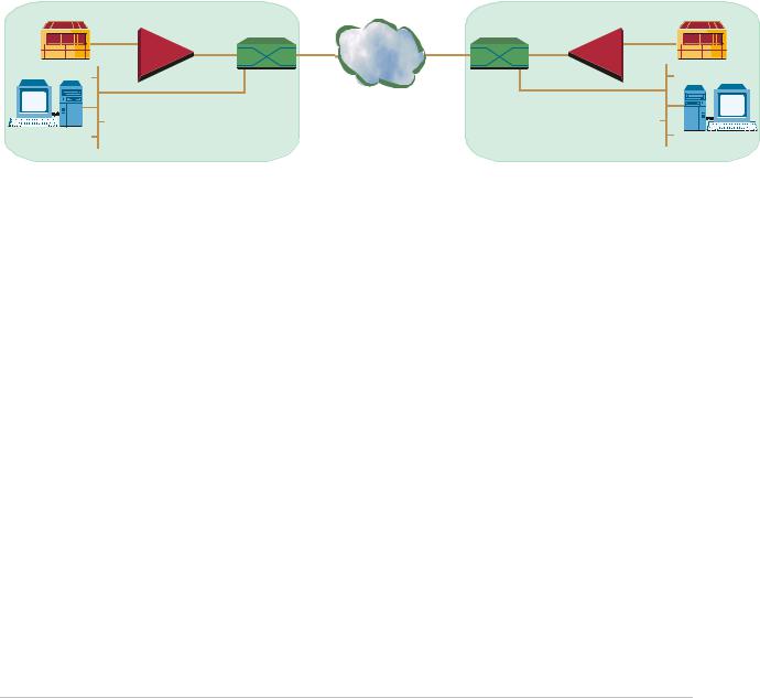
Typical IPmux-1/1E applications are shown with E1/T1, ISDN, and FXS interfaces. Figure 1-1 illustrates Multiplexing Voice and Data over an Ethernet Trunk.
Figure 1-2 shows an E1/T1 circuit extension over an IP based Network.
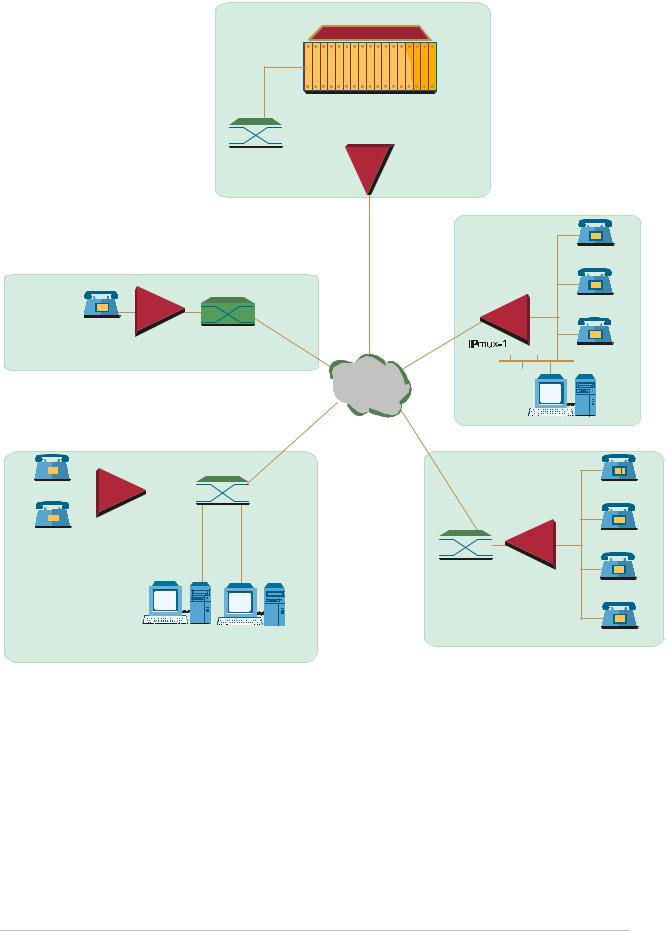
Figure 1-3 illustrates mixed BRI and POTS support application of V5.1 concentration of BRI remote terminals.
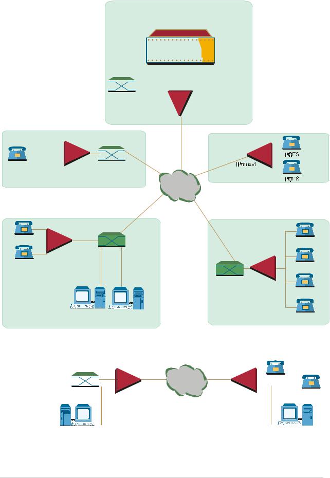
Figure 1-4 shows mixed BRI and POTS support application of S/U interface concentration.
Figure 1-5 illustrates extending BRI ports and LAN of a Small Office.
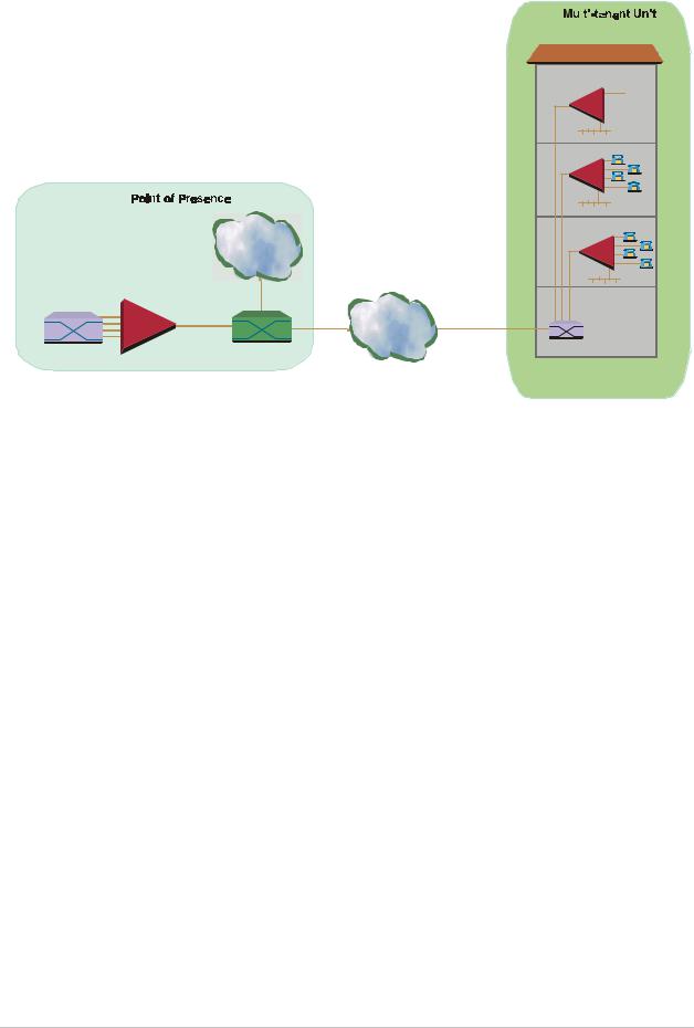
Figure 1-6 shows Ethernet-based multi-tenant with voice and data integrated access.
|
SITE A |
|
|
SITE B |
|
E1/T1 |
10/100 |
|
|
10/100 |
E1/T1 |
|
Mbps |
|
Ethernet |
Mbps |
|
|
|
|
|
|
|
PBX |
IPmux-1 |
Ethernet |
Ethernet |
IPmux-1 |
PBX |
|
|
||||
|
|
Switch |
Switch |
|
|
Figure 1-1. Multiplexing Voice and Data over an Ethernet Trunk
1-2 Overview
Order from: Cutter Networks |
Ph:727-398-5252/Fax:727-397-9610 |
www.bestdatasource.com |
IPmux-1/1E Installation and Operation Manual |
Chapter 1 Introduction |
100 Mbps |
n × E1/T1 |
|
PSTN |
IPmux-16 |
PBX |
or |
|
IPmux-4 |
|
Ethernet |
|
Switch |
|
10/100 Mbps |
IP Network |
100 Mbps |
Fractional |
E1/T1 |
|||
|
|
Fiber |
|
|
|
IPmux-1 |
PBX |
Ethernet |
Public Internet |
|
|
Switch |
|
|


 Fractional
 E1/T1
E1/T1
PBX |
IPmux-1 |
Figure 1-2. E1/T1 Circuit Extension over an IP Based Network
Overview 1-3
Order from: Cutter Networks |
Ph:727-398-5252/Fax:727-397-9610 |
www.bestdatasource.com |
Chapter 1 Introduction |
IPmux-1/1E Installation and Operation Manual |
|
|
Megaplex
For BRI
Grooming
|
|
E1 Link |
|
|
V5.1 |
|
|
E1 CAS |
|
|
|||
|
|
|
|
|||
|
For FXS |
|
|
|
|
|
Telephone |
Grooming |
|
|
|||
|
|
|
|
|
|
|
Switch |
|
|
|
|
|
|
POTS
Fast Ethernet
IPmux-1 Switch
 Network
|
|
|
|
|
|
|
|
|
|
ISDN Telephone |
|
|
|
|
Fast Ethernet |
|
|||
|
|
|
|
|
|||||
|
|
|
|
|
|||||
|
|
|
|
|
|
|
|
|
|
|
|
|
|
|
|
|
|
Switch |
|
ISDN Telephone |
|
IPmux-1 |
|
||||||
|
|
|
|
|
|
||||
|
|
|
|
|
|
||||
|
|
|
|
|
|
|
|
|
|
Fast Ethernet
Switch
Computer Computer
Workstation Workstation
POTS
POTS
POTS
Computer
Workstation
ISDN Telephone
ISDN Telephone
IPmux-1
ISDN Telephone
ISDN Telephone
Figure 1-3. Mixed BRI and POTS Support Application (V5.1 Concentration of BRI Remote Terminals)
1-4 Overview
Order from: Cutter Networks |
Ph:727-398-5252/Fax:727-397-9610 |
www.bestdatasource.com |
IPmux-1/1E Installation and Operation Manual |
Chapter 1 Introduction |
|
|
Megaplex
|
|
|
|
|
|
|
|
|
|
|
|
|
|
|
|
|
|
|
|
|
|
|
|
|
|
For BRI |
|
|
|
||||
|
|
|
|
|
|
|
|
|
|
|
|
|
|
|
|
|
|
|
|
|
|
|
|
|
|
Grooming |
|
|
|
||||
|
|
|
|
|
|
|
|
|
|
|
|
|
|
|
|
|
|
|
|
|
|
|
|
|
|
|
|
|
|||||
|
|
|
|
|
|
|
|
|
|
|
|
|
|
|
|
|
|
|
|
|
|
|
|
|
|
|
|
|
|
|
|
|
|
|
|
|
|
|
|
|
|
|
|
|
|
E1 Link |
|
|
TE U Ports |
|
|
|
|||||||||||||||
|
|
|
|
|
|
|
|
E1 CAS |
|
|
|
|
|
|
|
|
|
|
|
|
|
|
|
|
|||||||||
|
|
|
|
|
|
|
|
|
|
|
|
|
|
|
|
|
|
|
|
|
|
|
|
||||||||||
|
|
|
|
|
|
|
|
For FXS |
|
|
|
|
|
|
|
|
|
|
|
|
|
|
|
|
|
||||||||
|
|
|
|
|
Telephone |
Grooming |
|
|
|
|
|
|
|
|
|
|
|
|
|
|
|
||||||||||||
|
|
|
|
|
|
|
|
|
|
|
|
|
|
|
|
|
|
|
|
|
|
|
|
|
|
|
|
|
|
|
|||
|
|
|
|
|
Switch |
|
|
|
|
|
|
|
|
|
|
|
|
|
|
|
|
|
|
|
|
|
|
|
|
|
|
||
|
|
|
|
|
|
|
|
|
|
|
|
|
|
|
|
|
|
|
|
|
|
|
|
|
|
|
|
|
|
|
|
|
|
|
|
|
|
|
|
|
|
|
|
|
|
|
|
|
|
|
|
|
|
|
|
|
|
|
|
|
|
|
|
|
|
|
|
|
|
|
|
|
|
|
|
|
|
|
|
|
|
|
|
|
|
|
|
|
|
|
|
|
|
|
|
|
|
|
|
|
|
|
|
|
|
|
|
|
|
|
|
|
|
|
|
|
|
|
|
|
|
|
|
|
|
|
|
|
|
|
|
|
|
|
|
|
|
|
|
|
|
|
|
|
|
|
|
|
|
|
|
|
|
|
|
|
|
|
|
|
|
|
|
|
|
|
|
|
|
POTS |
IPmux-1 |
Fast Ethernet |
|
|
|
|
|
|
||
Switch |
|
|
||||||||
|
|
|
|
|||||||
|
|
|
|
|
|
|
|
|
|
|
|
|
|
|
|
|
|
|
|
|
|
Network
ISDN Telephone |
Fast Ethernet |
|
ISDN Telephone |
|
Switch |
|
|
IPmux-1 |
|
|
|
ISDN Telephone |
|
|
ISDN Telephone |
|
|
Fast Ethernet |
IPmux-1 |
|
|
Switch |
|
|
|
ISDN Telephone |
|
|
|
|
|
Computer |
Computer |
|
ISDN Telephone |
Workstation |
Workstation |
|
|
|
|
|
|
|
|
|
Figure 1-4. |
U Interface Concentration |
|
|
|
|
|
|
|
|
|
|
|
|
|
|
|
||
|
|
|
|
|
TE |
|
NT |
|
|
|
|
|
|
|
|
|
|
|
|
|
|
|
|
|
|
|
S |
Network |
|
|
ISDN Telephone |
||||||||||||||||
|
|
|
|
||||||||||||||||||||
|
|
|
|
|
|
|
|
||||||||||||||||
|
|
|
|
|
|
|
|
|
|
|
|
|
|
|
|
|
|
|
|
|
|
|
|
PBX |
|
|
|
|
|
|
|
|
|
|
|
|
|
|
ISDN Telephone |
||||||||
|
|
|
IPmux-1E |
IPmux-1E |
|
|
|
|
|
|
|
||||||||||||
|
|
|
|
|
|
|
|
|
|
|
|
|
|
|
|
|
|
||||||
|
|
|
|
|
|
|
|
|
|
|
|
|
|
|
|
|
|
|
|
|
|
|
|
|
|
|
|
|
|
|
|
|
|
|
|
|
|
|
|
|
|
|
|
|
|
|
|
|
|
|
|
|
|
|
|
|
|
|
|
|
|
|
|
|
|
|
|
|
|
|
|
|
|
|
|
|
|
|
|
|
|
|
|
|
|
|
|
|
|
|
|
|
|
|
|
|
|
|
|
|
|
|
|
|
|
|
|
|
|
|
|
|
|
|
|
|
|
|
|
|
|
|
|
|
|
|
|
|
|
|
|
|
|
|
|
|
|
|
|
|
|
|
|
Computer |
Computer |
Workstation |
Workstation |
Figure 1-5. Extending BRI Ports of a Small Office
Overview 1-5
Order from: Cutter Networks |
Ph:727-398-5252/Fax:727-397-9610 |
www.bestdatasource.com |
Chapter 1 Introduction |
IPmux-1/1E Installation and Operation Manual |
||||||||||||||
|
|
|
|
|
|
|
|
|
|
|
|
|
|
|
|
|
|
|
|
|
|
|
|
|
|
|
|
|
|
|
|
|
|
|
|
|
|
|
|
|
|
|
|
|
|
|
|
|
|
|
|
|
|
|
|
|
|
|
|
|
|
|
|
E1/T1
|
|
IPmux-1 |
|
|
FXS ISDN |
|
|
Phones |
|
|
IPmux-1E |
|
|
BRI |
Internet |
|
|
|
|
IPmux-1E |
Switch |
IP Network |
Ethernet |
|
|
Switch |
Telephony Switch IPmux-16
Figure 1-6. Ethernet-based Multi-tenant Application with Voice and Data Integrated Access
Features
IPmux-1/1E is a 1U high, easy-to-install standalone unit. A rack mount installation option is available.
IPmux-1 can be ordered with AC or DC power supply. IPmux-1E is only available with AC power supply.
Management
IPmux-1/1E can be managed locally by connecting an ASCII terminal to the RS-232 port on the front panel or remotely via Telnet or SNMP. The SNMP management capability enables fully graphical, user-friendly management using the RADview network management stations offered by RAD, as well as management by other SNMP-based management systems.
T1
The T1 port and framers comply with ANSI T1.403 standards. T1 jitter performance is according to G.704, G.824, TR-62411. The T1 framers support pass-through, SF, ESF and CAS framing. The T1 port supports long haul and short haul input signals and can be monitored for alarms and error statistics. FDL and transmit PRM for T1/ESF are also supported.
E1
The E1 port complies with G.703, G.704, and G.823 standards. E1 framers comply with G.704. The E1 framers support pass-through, framed, CRC4 MF and CAS MF framing. The E1 port supports long haul and short haul input signals and can be monitored for alarms and error statistics.
1-6 Overview
Order from: Cutter Networks |
Ph:727-398-5252/Fax:727-397-9610 |
www.bestdatasource.com |

IPmux-1/1E Installation and Operation Manual |
Chapter 1 Introduction |
|
|
ISDN BRI
IPmux-1E has 4-ports, S-interface only. Each port can be configured as either NT or TE (Network/User) by jumper and software; NT or TE is configured per device.
IPmux-1E can be configured to 1, 2, 3 or 4 active ports.
IPmux-1E works in transparent mode (no termination/compression of D channels). It operates opposite IPmux with E1/T1 and a Megaplex unit as a concentrator in transparent mode or opposite another IPmux-1E with ISDN BRI ports.
FXS
IPmux-1E has 4 FXS interface ports for POTS connection. A central IPmux unit with an E1/T1 CAS interface can groom FXS channels from the remote site.
IP
The data stream coming from the E1 or T1 port is converted into IP packets that are transported over the Fast Ethernet port, and vice versa.
TDM bytes are encapsulated in a UDP frame that runs over IP and over Ethernet.
The number of TDM bytes in an IP frame is configurable for throughput/delay tradeoff.
Each device has a single IP address (Host IP). A configurable destination IP address is assigned to the IP packets. IP ToS field support can be configured for IP Level Priority.
Ethernet User Port
IPmux-1E has an optional user port for user LAN connectivity/access as well as TDM services connectivity. A transparent bridging mode is supported (user/network Ethernet port) and a second mode which enables user port rate limiting.
Ethernet Physical Port
IPmux-1/1E is available with Ethernet ports (user or network port). The Ethernet network port can be either UTP or fiber. The Ethernet user port is UTP only.
•UTP option – A standard 10/100BaseT half/full duplex port with auto-negotiation support. If auto-negotiation is disabled, IPmux-1 capabilities can be configured to 100BaseT – full duplex, 100BaseT – half duplex, 10BaseT – full duplex, or 10BaseT – half-duplex. Half-duplex operation in IPmux-1 network port is not recommended, because collisions and backoffs cause large delay variation and may exceed the delay variation buffer tolerance at the receiving end, causing buffer underflows and errors to occur.
•Fiber option – standard 100BaseF full duplex port (see Table 1-1).
Overview 1-7
Order from: Cutter Networks |
Ph:727-398-5252/Fax:727-397-9610 |
www.bestdatasource.com |

Chapter 1 Introduction IPmux-1/1E Installation and Operation Manual
Table 1-1. Fiber Options
Interface Type |
Wavelength |
Optical Power |
Receive |
Optical |
Loss |
|
|
|
(nm) |
(dBm) |
|
Sensitivity |
Budget |
(dB/km) |
|
|
|
Min |
Max |
(dBm) |
(dB)* |
Min |
Max |
|
|
|
|
|
|
|
|
SC Multimode |
1300 |
–20 |
–14 |
–31 |
8* |
1 |
4 |
|
|
|
|
|
|
|
|
SC Single mode |
1300 |
–20 |
–14 |
–31 |
8* |
0.5 |
0.8 |
|
|
|
|
|
|
|
|
LC Multimode |
1300 |
–19 |
–14 |
–32 |
10* |
1 |
4 |
|
|
|
|
|
|
|
|
LC Single mode |
1300 |
–15 |
–8 |
–32 |
14* |
0.5 |
0.8 |
•Permitted fiber optic cable length differs according to fiber characteristics, splices, and connectors.
Note When a user port option (only UTP) is chosen, the network fiber option is LC. If there is no user port, the network fiber option is SC.
To calculate Optical Budget:
Optical Budget [dB] =
Receive Sensitivity – Optical Power –3 (Aging) – Connectors/Patch Panels Loss
To calculate Distance:
Distance = Optical Budget/Maximum Loss
Mode of Operation
IPmux-1 can operate in three different modes:
•Unframed E1/T1 over UDP over IP over Ethernet
•Fractional E1/T1 over UDP over IP over Ethernet
•Fractional E1/T1 with CAS over UDP over IP over Ethernet.
IPmux-1E with BRI can operate in two modes:
•NT mode
•TE mode.
IPmux-1E with FXS can operate in three modes:
•E1 mode
•T1 mode D4 mode
•T1 ESF mode.
1-8 Overview
Order from: Cutter Networks |
Ph:727-398-5252/Fax:727-397-9610 |
www.bestdatasource.com |

IPmux-1/1E Installation and Operation Manual |
Chapter 1 Introduction |
|
|
Note IPmux E1/T1 working opposite IPmux-1E with BRI ports should work in Fractional E1/T1 mode (no CAS). When working opposite IPmux-1E with FXS, use E1/T1 CAS mode.
QoS
QoS support:
•Labeling IP level priority (ToS) for TDMoIP packets
•VLAN tagging and priority labeling according to IEEE 802.1p&q for TDMoIP packets.
The user can configure the ToS (Type of Service) of the outgoing TDMoIP packets. This allows an en-route Layer 3 router or switch, which supports ToS, to give higher priority to IPmux-1/1E TDMoIP traffic for delay-sensitive and secure applications. IPmux-1 allows you to configure the WHOLE ToS byte field, since different vendors may use different bits to tag packets for traffic prioritization. This also enables you to work according to various RFC definitions (for example RFC 2474, RFC 791). The user can also configure VLAN priority bits for
Level 2 Priority.
Timing
IPmux-1 maintains synchronization between TDM devices by deploying advanced clock distribution mechanisms.
Available timing modes are:
•Loopback
•Adaptive
•Internal Clock
•External Clock.
Note For more details see Timing Modes in Section 1.3.
Standards
G.703, G.704, G.706, G.823, ANSI T1.403, AT&T TR-62411, G.824, IEEE 802.3, I.430, IEEE 802.3D, IEEE 802.1p&q, EMC Class B compliance – EN55022 Class B
Overview 1-9
Order from: Cutter Networks |
Ph:727-398-5252/Fax:727-397-9610 |
www.bestdatasource.com |

Chapter 1 Introduction |
IPmux-1/1E Installation and Operation Manual |
|
|
1.2 Physical Description
IPmux-1 is a 1U high 19-in (IPmux-1E is a 1U high ½ 19-in), easy-to-install standalone unit. A rack mounting kit option is available (ordered separately).
Figure 1-7 shows a 3-dimensional view of IPmux-1; Figure 1-8 shows a 3-dimensional view of IPmux-1E.
Figure 1-7. IPmux-1 3-D View
Figure 1-8. IPmux-1E 3-D View
1-10 |
Physical Description |
Order from: Cutter Networks |
Ph:727-398-5252/Fax:727-397-9610 |
www.bestdatasource.com |
IPmux-1/1E Installation and Operation Manual |
Chapter 1 Introduction |
|
|
Front Panel
The control interface and indicator LEDs are located on the front panel of IPmux-1/1E. For further details see Chapter 2.
Rear Panel
User and network ports and power supply are located on the rear panel of
IPmux-1/1E. For further details see Chapter 2.
1.3 Functional Description
IPmux-1 supports a single E1 or T1 TDM interface; it provides TDM connectivity across the IP network. A single bundle (group of timeslots) can be transmitted to a predefined far-end bundle. IPmux-1 supports ICMP (ping), and generates ARP in case of unknown next hop MAC addresses, answers ARP requests, and supports 802.3 Ethernet format.
IPmux-1E supports 4 BRI or 4 FXS ports for transparent connectivity over the IP network.
Both IPmux-1 and IPmux-1E support Ethernet user port for user LAN connectivity.
Configuration and management are provided via the IPmux-1/1E local terminal, Telnet or RADview management tool (SNMP).
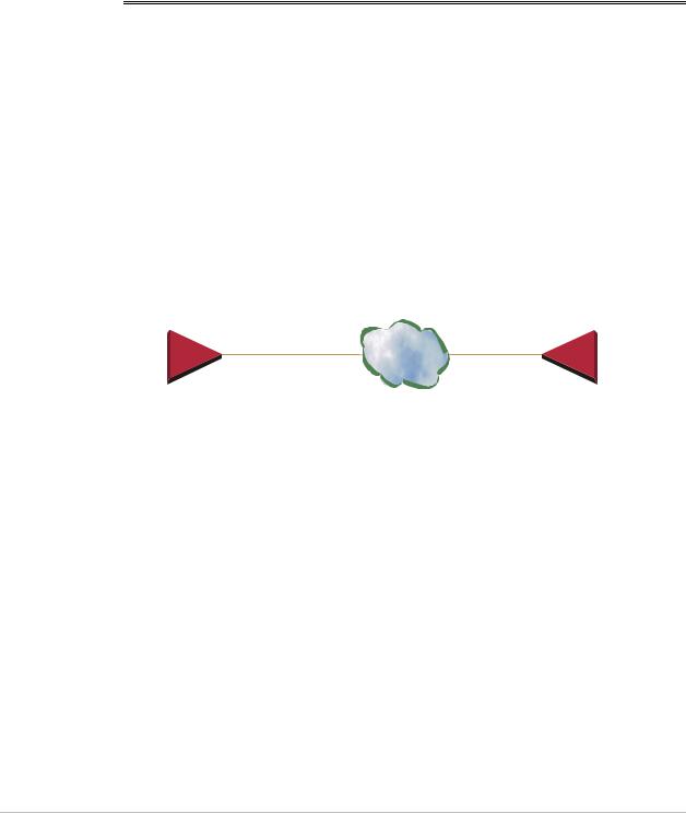
Figure 1-9 shows a typical application for IPmux-1.
E1/T1 Port |
10/100BaseT |
IP |
10/100BaseT |
E1/T1 Port |
|
100BaseF |
100BaseF |
||||
|
|
|
|||
|
IPmux-1 |
|
|
IPmux-1 |
Figure 1-9. IPmux-1 Functional Diagram
IPmux-1/1E works in conjunction with the rest of the IPmux product line (see Figure 1-10). The combination of IPmux products provides up to 31 per E1 or 24 per T1 remote bundles, attached to one central IPmux-4/16 (see Figure 1-10).
Functional Description |
1-11 |
Order from: Cutter Networks |
Ph:727-398-5252/Fax:727-397-9610 |
www.bestdatasource.com |

Chapter 1 Introduction |
IPmux-1/1E Installation and Operation Manual |
|
|
Sub E1/T1
IPmux-1
Sub E1/T1
IPmux-1
E1/T1 Line 1 |
|
IP over |
E1/T1 Line 2 |
|
|
|
Ethernet |
|
E1/T1 Line 3 |
|
|
|
||
E1/T1 Line 4 |
|
IPmux-4/16 |
|
||
|
|
IPmux-1 |
|
Sub E1/T1 |
|
||
|
|
IPmux-1
Sub E1/T1
Figure 1-10. Grooming of Timeslots from Remote Sites into a
Single E1/T1 Port at Central Site
Other BRI/FXS applications are shown in Figure 1-3, Figure 1-4, and Figure 1-5.
Operation Modes
IPmux-1 E1/T1
IPmux-1 E1/T1 operation modes are:
•Unframed
•Fractional
•Fractional with CAS.
Unframed
In the transparent mode, the incoming bit stream from each channel (regardless of framing) is converted into IP over Ethernet frames. This option provides clear channel end-to-end service (unframed).
Fractional
In the fractional mode, the incoming bit stream is regarded as a sequence of n x 64 kbps channel groups (according to framing). Each predefined group of
channels is converted into a structure block. The structure block is packetized into IP frames and transmitted.
This mode allows transmission of several selected timeslots without the whole E1 or T1 frame, as in transparent mode.
Note Use Fractional mode when grooming ISDN BRI channels from a remote IPmux-1E unit.
1-12 |
Functional Description |
Order from: Cutter Networks |
Ph:727-398-5252/Fax:727-397-9610 |
www.bestdatasource.com |
IPmux-1/1E Installation and Operation Manual |
Chapter 1 Introduction |
|
|
Fractional with CAS
In the fractional-with-CAS mode, the structure block (as described under Fractional Operation Modes, above) also includes Channel Associated Signaling (CAS). The relevant portion of the signaling channel is packetized and sent to the destination.
Note Use Fractional with CAS mode when grooming FXS channels from a remote IPmux-1E unit.
IPmux-1E ISDN BRI
The IPmux-1E ISDN BRI S interface operation modes are:
•TE mode
•NT mode.
The selected mode applies to all 4 channels. The NT or TE mode is determined by phantom feeding and software setting, which is enabled/disabled by jumpers located on the BRI card (see Chapter 2).
TE Mode
All four channels are configured in TE (Terminal Equipment) as defined in I.430.
NT Mode
All four channels are configured in NT (Network Termination) as defined in I.430. TE Deactivation is not used in NT mode, and Layer 1 is in active mode all the time.
Note If phantom feeding is enabled by the jumpers, the TE mode cannot be selected as the IPmux-1E operation mode. If phantom feeding is disabled, both NT and TE are valid options.
IPmux-1E FXS
IPmux-1E FXS operates in:
•E1 mode
•T1-D4 mode
•T1 ESF mode.
Functional Description |
1-13 |
Order from: Cutter Networks |
Ph:727-398-5252/Fax:727-397-9610 |
www.bestdatasource.com |
Chapter 1 Introduction |
IPmux-1/1E Installation and Operation Manual |
|
|
The IPmux-1E FXS operation modes allow IPmux to work opposite E1, T1-D4, or T1-ESF. Two parameters are set internally when choosing one of the options:
•A-Law/µ-Law
−A-Law when E1 mode is selected
−µ-Law is used in PCM CODEC when T1 (D4 or ESF) is selected.
•E1, T1-D4, and T1-ESF with CAS are structured differently in the TDM ↔IP interworking function. A different structure must be used when working opposite each one.
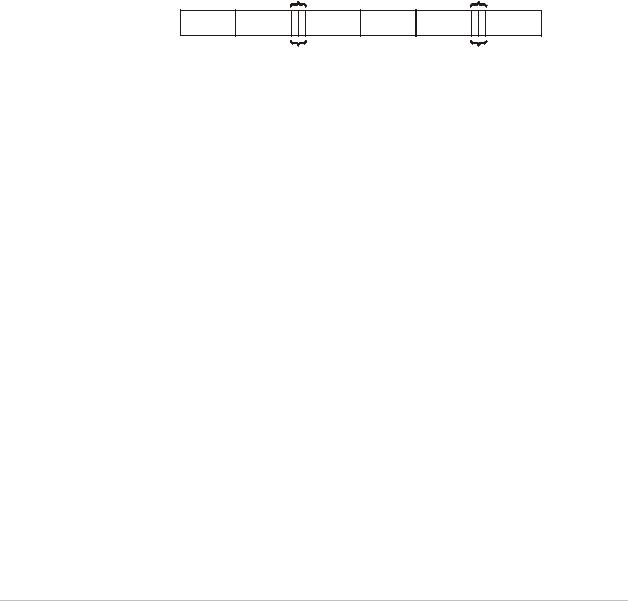
BRI/FXS TS Assignment in a Bundle
BRI
The TS assignment in a Bundle for IPmux-1E with BRI (when working opposite IPmux with E1/T1 or Megaplex) is assigned as follows:
|
First Channel |
|
|
Second Channel |
|
B1 |
B2 |
D |
B1 |
B2 |
D … |
MSB Bits 7, 6 contain D channel information
MSB Bits 7, 6 contain D channel information
Figure 1-11. TS Assignment in a Bundle for IPmux-1E/BRI
As shown in Figure 1-11, the 4 BRI channels consume 12 timeslots in the Bundle. The E1/T1 IPmux should work in framed mode (no CAS).
The three TS groups in the bundle are assigned according to BRI channel numbers; the first group is assigned to the lowest BRI channel that is enabled, etc.
FXS
The TS assignment in a Bundle for IPmux-1E with FXS is straightforward. Each timeslot in a Bundle is assigned to a specific FXS channel. Time slots in the bundle are assigned according to FXS channel numbers; the first timeslot is assigned to the lowest FXS channel that is configured, etc. As shown in Figure 1-11, the 4 FXS channels consume 4 timeslots in the Bundle.
The E1/T1 IPmux that works opposite the FXS channels should work in Framed with CAS mode.
Testing
Diagnostic capabilities include E1/T1 or BRI S local and remote loopback tests for rapid localization of faults. The E1/T1 or BRI S channel can be looped locally, toward the line, or toward the remote end (see Chapter 4 for more information).
Remote Loopback and Tone Injection are available for the FXS port.
1-14 |
Functional Description |
Order from: Cutter Networks |
Ph:727-398-5252/Fax:727-397-9610 |
www.bestdatasource.com |

IPmux-1/1E Installation and Operation Manual |
Chapter 1 Introduction |
|
|
Timing Modes
The E1/T1 Tx clock, or ISDN/FXS PCM clock, can operate in several timing modes to provide maximum flexibility for connecting the IPmux-1 E1, T1, ISDN or FXS channels.
Each of the clocks must be configured correctly on both the Receive and Transmit ends to ensure proper operation and prevent pattern slips (see Figure 1-12,
Figure 1-14, and Figure 1-15).
E1/T1
The E1/T1 available Tx modes are:
•Loopback Timing – the E1/T1 Tx clock is derived from the E1/T1 receive (Rx) clock.
•Adaptive Timing – in this mode, the E1 or T1 Tx clock is regenerated using the Adaptive method. In this method, the fill level of the buffer receiving packets is monitored. If the buffer begins to overfill, the regenerated Tx clock frequency increases to avoid overflow. If the buffer begins to empty, the Tx clock (toward the TDM device) decreases to avoid underflow.
•Internal Clock Timing – in this mode, the Tx clock is received from an internal oscillator.
•External Clock Timing – in this mode the Tx clock is taken from the external clock input (Ordering option). The External Clock port also outputs the input clock signal to allow connection to other units, if needed.
Note In Adaptive Timing mode the regenerated clock is subject to network Packet Delay Variation and may not comply with jitter and wander specifications.
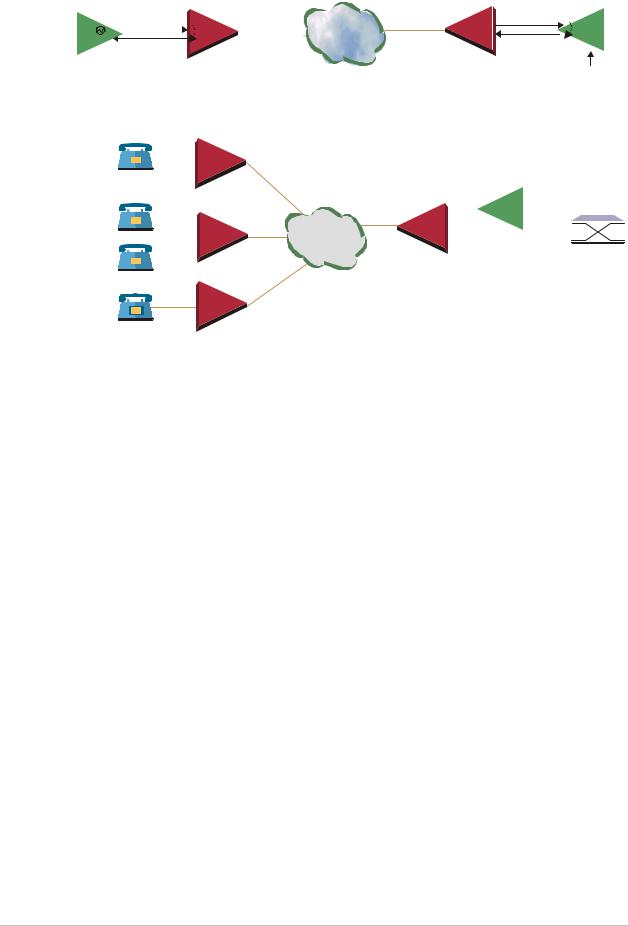
FXS/BRI
The available timing modes for the PCM clock are:
•Loopback Timing – available only when IPmux-1E BRI is configured as TE (not available in BRI NT mode or for FXS interface). In this mode the PCM clock is derived from Channel 1.
It is recommended not to deactivate Channel 1 while it is in loopback clock so that data will not be damaged. If Channel 1 is disconnected or deactivated (by the NT side), the PCM clock will change to Internal clock and a momentary
Warning disruption will occur to the other channels (2,3,4), if they are active.
•Adaptive Mode – the clock is regenerated using the Adaptive method, where the rate of arriving packets is used to regenerate the clock (see E1/T1).
•Internal Mode – the clock is received from an internal oscillator.
Functional Description |
1-15 |
Order from: Cutter Networks |
Ph:727-398-5252/Fax:727-397-9610 |
www.bestdatasource.com |

Chapter 1 Introduction |
IPmux-1/1E Installation and Operation Manual |
|
|
Network Timing Schemes
The following paragraphs describe typical timing schemes and the correct timing mode settings for achieving end-to-end synchronization.
External Network Timing
When the edges of the network are synchronized according to an external network clock source, all the IPmux-1 units should be configured to work in loopback timing mode (see Figure 1-12). This topology enables any-to-any connectivity.
Clock from External Distribution Network
|
E1/T1 |
|
|
E1/T1 |
|
||
|
E1/T1 |
IPmux-1 |
IPmux-1 |
E1/T1 |
|
||
E1/T1 Device |
LBT Mode |
E1/T1 Device |
|||||
|
IP over |
||||||
|
LBT Mode |
|
Ethernet |
|
|
||
|
|
|
|
|
|||
|
|
|
|
|
E1/T1 |
|
|
|
|
|
IPmux-1 |
IPmux-1 |
E1/T1 |
|
|
|
|
|
|
||||
E1/T1 Device LBT Mode |
LBT Mode |
E1/T1 Device |
|||||
Figure 1-12. IPmux-1 in Loopback Timing Mode
External timing from the network can also be issued to IPmux-1 by External Clock input; in this case, the E1/T1 device will use the LBT mode.
Clock from External Distribution Network
E1/T1 Device |
|
|
|
|
E1/T1 Device |
|
|
|
|
|
IP over |
|
E1/T1 |
|
|
|
|
|
|
|
|
|
|
IPmux-1 |
Ethernet |
|
E1/T1 |
|
|
|
|
|||
|
|
|
|
|
||
LBT Mode |
|
|
IPmux-1 |
|||
External |
|
|
LBT Mode |
|||
|
|
Clock Mode |
|
|
|
|
Figure 1-13. IPmux-1 in External Clock Mode
Single Source Clock Network
When a common clock is not available on all the ends of the network one of the IPmux-1 devices is configured to work in Loopback timing mode, while the other IPmux-1 device is configured to work in Adaptive timing mode (see Figure 1-14).
1-16 |
Functional Description |
Order from: Cutter Networks |
Ph:727-398-5252/Fax:727-397-9610 |
www.bestdatasource.com |
IPmux-1/1E Installation and Operation Manual |
|
|
|
|
|
|
|
|
Chapter 1 Introduction |
||||||||||||||
|
|
|
|
|
|
|
|
|
|
|
|
|
|
|
|
|
|
|
|
|
|
|
|
E1/T1 Device |
|
Loopback Timing Mode |
|
|
|
|
|
Adaptive |
|
|
Mode |
|
|
|
E1/T1 Device |
||||||||
|
|
|
|
|
|
|
|
|
|||||||||||||||
Master Clock |
E1/T1 |
|
|
|
IP over |
|
|
|
|
|
|
E1/T1 |
|
|
|
|
|
||||||
|
|
|
|
|
|
|
|
|
E1/T1 |
|
|
|
|
|
|||||||||
Source Device |
E1/T1 |
|
Ethernet |
|
|
|
|
|
|
|
|
|
|
|
|||||||||
|
|
|
|
IPmux-1 |
|
|
|
|
|
|
|
||||||||||||
|
|
|
|
|
IPmux-1 |
|
|
|
|
|
|
|
|
|
|||||||||
|
|
|
|
|
|
|
|
|
|
|
|
|
|
|
|
|
|
|
Remote Loopback |
||||
|
|
|
|
|
|
|
|
|
|
|
|
|
|
|
|
|
|
|
Timing Device |
||||
|
|
|
Figure 1-14. IPmux-1 in Adaptive Timing Mode |
|
|
|
|
|
|
|
|||||||||||||
|
|
|
|
|
Adaptive |
|
|
|
|
|
|
|
|
|
|
|
|
|
|
|
|
|
|
|
|
|
|
|
|
|
|
Grooming |
|
|
|
|
|
|
|
||||||||
|
|
|
|
|
|
|
|
|
|
|
|
|
|
|
|
|
|
|
|||||
ISDN |
|
|
|
|
|
|
|
|
|
|
|
|
|||||||||||
|
|
|
|
|
|
|
|
LBT |
|
|
|
of BRI |
LBT |
|
|
|
|
||||||
|
|
|
|
|
|
|
|
|
|
|
E1 |
|
|
|
|
|
|
||||||
|
|
|
|
|
Adaptive |
|
|
|
|
|
|
|
|
|
|
|
|||||||
|
|
|
|
|
IP over |
|
|
|
Megaplex |
|
|
V5.1 |
|
|
|
||||||||
ISDN |
|
|
|
|
|
|
|
|
|
|
|||||||||||||
|
|
|
|
|
|
|
|
|
|
|
|
|
|
|
|||||||||
Ethernet |
|
|
|
Grooming of FXS |
|
|
|
|
|||||||||||||||
|
|
|
|
|
|
|
|
|
|
|
Telephone |
||||||||||||
|
|
|
|
|
|
|
|
IPmux-4/16 |
in E1 CAS |
|
|
||||||||||||
|
|
|
|
|
|
|
|
|
|
Switch |
|||||||||||||
|
|
|
|
|
|
|
|
|
|
|
|
|
|
|
|
|
|
|
|
|
|||
ISDN |
Adaptive |
|
POTS
Figure 1-15. IPmux-1E in Adaptive Timing Mode
Frame Format
The Ethernet frame sent by the IPmux-1 is a UDP datagram that transfers E1/T1 payload bytes over IP over Ethernet (UDP payload + UDP header + IP header + Ethernet header).
The UDP payload size is equal to TDM bytes per frame (TDM bytes/frame configuration).
Table 1-2 specifies the structure of the different headers, special fields, and the payload in the Ethernet packet.
|
|
|
|
|
MAC |
IP |
UDP |
Payload |
|
|
|
|
|
|
|
|
|
|
|
Figure 1-16. TDMoIP Frame Structure
Functional Description |
1-17 |
Order from: Cutter Networks |
Ph:727-398-5252/Fax:727-397-9610 |
www.bestdatasource.com |

Chapter 1 Introduction |
IPmux-1/1E Installation and Operation Manual |
|
|
Table 1-2. Ethernet Frame Structure
MAC
Layer
LLC
Layer
IP Layer
UDP
Layer
Data
Layer
MAC
Layer
|
|
Field length (bytes) |
Field |
|
|
|
|
7 |
Preamble |
||
|
|
|
|
1 |
SFD |
||
|
|
|
|
6 |
Destination MAC Address |
||
|
|
|
|
6 |
Source MAC Address |
||
|
|
|
|
2 |
Type |
||
|
|
|
|
1 |
Vers/HLEN |
||
|
|
|
|
1 |
Service Type |
||
|
|
|
|
2 |
Total Length |
||
|
|
|
|
2 |
Identification |
||
|
|
|
|
1 |
Flags/Fragment Offset (most) |
||
|
|
|
|
1 |
Fragment Offset (least) |
||
|
|
|
|
1 |
Time to Live |
||
|
|
|
|
1 |
Protocol |
||
|
|
|
|
2 |
Header Checksum |
||
|
|
|
|
4 |
Source IP Address |
||
|
|
|
|
4 |
Destination IP Address |
||
|
|
|
|
2 |
UDP Source Port |
||
|
|
|
|
2 |
UDP Destination Port |
||
|
|
|
|
2 |
UDP Message Length |
||
|
|
|
|
2 |
UDP Checksum |
||
|
|
|
|
... |
Payload |
||
|
|
|
|
4 |
CRC |
||
|
|
|
|
Note: IEEE 802.1p&q VLAN Tagging (additional 4 bytes if enabled)
Note: The UDP source port field is used to transfer the destination bundle number.
VLAN Support
VLAN, according to IEEE 802.1p&q, adds four bytes to the MAC layer of the Ethernet frame. The contents of these bytes, MAC layer priority and VLAN ID, can be set by the user. In this mode, only VLAN format frames are sent and received by IPmux-1. Figure 1-17 describes the VLAN tag format.
1-18 |
Functional Description |
Order from: Cutter Networks |
Ph:727-398-5252/Fax:727-397-9610 |
www.bestdatasource.com |

IPmux-1/1E Installation and Operation Manual |
Chapter 1 Introduction |
|
|
81 |
00 |
|
|
802.1D Tag Protocol Type
user_priority |
0 |
|
|
|
VID |
|
|
|
CFI = |
|
|
|
|
8 |
6 |
5 |
4 |
1 |
8 |
1 |
|
Priority |
|
|
|
|
VLAN ID |
Figure 1-17. VLAN Tag Format (802.1p&q)
UDP Support
Table 1-3. UDP Ports Definition
Field Length (Bits) |
Field Description |
Value |
Function |
|
|
|
|
2 bytes |
UDP Source Port |
2–497d* |
Destination timeslots bundle |
|
|
|
|
2 bytes |
UDP Destination Port |
2142d |
Standard TDMoIP UDP port |
|
|
|
|
* The MSB of this field can be either 1 or 0 for inband end-to-end proprietary signaling.
Note The UDP Source Port field is used for destination timeslots bundle indication. For example, if the destination is:
Bundle 1 – 02, Bundle 2 – 03, Bundle 3 – 04, Bundle 4 – 05, etc.
For more information about VLAN tagging, refer to IEEE Std 802.1p&q.
Packet Delay Variation
Packets are transmitted at set intervals. Packet Delay Variation is the maximum deviation from the nominal time the packets are expected to arrive at the far end device. IPmux-1 has a buffer that compensates for the deviation from the expected packet arrival time to prevent IPmux-1 buffers from emptying out or overflowing.
Packet Delay Variation is an important network parameter. Large PDV (exceeding the jitter buffer configuration) will cause receive buffer underflows and errors at the E1/T1 level (see Figure 1-18).
To compensate for large PDV, configure the PDVT (jitter) buffer to a higher value.
Functional Description |
1-19 |
Order from: Cutter Networks |
Ph:727-398-5252/Fax:727-397-9610 |
www.bestdatasource.com |

Chapter 1 Introduction |
IPmux-1/1E Installation and Operation Manual |
|
|
Packets Leaving IPmux-1  t
t
Packets Arriving  t
t
PDV
Figure 1-18. Packet Delay Variation
PDVT (Jitter) Buffer
IPmux-1 is equipped with a Packet DVT (Delay Variation Tolerance) buffer. The PDVT buffer or jitter buffer is filled by the incoming IP packets and emptied out to fill the E1/T1 stream. The buffer begins to empty out only after it is half full in order to compensate for packet starvation from the Ethernet side. The time it takes for half of the buffer to empty out is the maximum DVT time. Delay Variation Tolerance is configurable. The PDVT (jitter) buffer is designed to compensate for packet delay variation caused by the network + intrinsic PDV.
It supports a delay variation of up to 300 ms for E1 or T1.
To configure jitter buffer depth:
Estimated or Measured PDV introduced by the network + intrinsic PDV (if it exists) introduced by the module as a result of configuring the
TDM bytes / frame > 48 (see explanation of calculating intrinsic PDV, below).
Intrinsic PDV
If TDM bytes/frame is greater than 48, there is an intrinsic delay variation (intrinsic PDV). The intrinsic PDV introduced by the module is a function of n>1 in
TDM bytes/frame configuration as follows:
I.PDV (ms) = [(n-1) x 1000) / (frames per second × n]
where n = |
Configured TDM bytes/frame |
(n = 1 to 8). |
|
48 |
|||
|
|
Note For a bundle that contains a few timeslots (i.e. 1–3) the minimal jitter buffer should be 6 ms.
PDVT Buffer Effect on Delay
The PDVT buffer is on the TDM path; it adds to the total end-to-end delay (see delay calculation, below).
Ethernet Throughput
Configuring the TDM bytes per frame (TDM bytes/frame) parameter can reduce Ethernet throughput (bandwidth or traffic travelling through the Ethernet). This parameter controls the number of TDM bytes encapsulated in one frame. The TDM bytes/frame parameter can be configured to n x 48 bytes where n is an
1-20 |
Functional Description |
Order from: Cutter Networks |
Ph:727-398-5252/Fax:727-397-9610 |
www.bestdatasource.com |

IPmux-1/1E Installation and Operation Manual |
Chapter 1 Introduction |
|
|
integer between 1 and 8. Configuring TDM bytes/frame to a higher value reduces the IP/Ethernet overhead segment of the total packet and thus can significantly reduce the total Ethernet throughput.
On the other hand, packetization delay and intrinsic packet delay variation (PDVT) are increased; this contributes to a higher end-to-end delay. This effect can be small and negligible when a full E1 (or many timeslots) are transferred but can be very significant when few timeslots are transferred. In this case, the packetization delay and the intrinsic PDV when configuring a large value of
TDM bytes/frame can be very large and may exceed the maximum PDVT (jitter) buffer on the receiving end. Table 1-4 and Table 1-5 show throughput as a function of the TDM bytes/frame configuration for full E1 and full T1.
|
Table 1-4. |
Ethernet Throughput – Unframed E1 |
|
||
|
|
|
|
|
|
TDM |
Frame |
Overhead |
Overhead |
Packets |
Throughput |
bytes/frame |
Length |
(bytes) |
(%) |
per |
(Mbps) |
|
(bytes) |
|
|
Second |
|
|
|
|
|
|
|
48 |
94 |
46 |
96 |
5447 |
4.1 |
|
|
|
|
|
|
96 |
142 |
46 |
48 |
2724 |
3.1 |
|
|
|
|
|
|
144 |
190 |
46 |
32 |
1816 |
2.76 |
|
|
|
|
|
|
192 |
238 |
46 |
24 |
1362 |
2.6 |
|
|
|
|
|
|
240 |
286 |
46 |
19 |
1089 |
2.5 |
|
|
|
|
|
|
288 |
334 |
46 |
16 |
908 |
2.43 |
|
|
|
|
|
|
336 |
382 |
46 |
14 |
778 |
2.38 |
|
|
|
|
|
|
384 |
430 |
46 |
12 |
681 |
2.34 |
|
|
|
|
|
|
|
Table 1-5. |
Ethernet Throughput – Unframed T1 |
|
||
|
|
|
|
|
|
TDM |
Frame |
Over head |
Over head |
Packets |
Throughput |
bytes/frame |
length |
(bytes) |
(%) |
per |
(Mbps) |
|
(bytes) |
|
|
Second |
|
|
|
|
|
|
|
48 |
94 |
46 |
96 |
4107 |
3.08 |
|
|
|
|
|
|
96 |
142 |
46 |
48 |
2054 |
2.32 |
|
|
|
|
|
|
144 |
190 |
46 |
32 |
1369 |
2.07 |
|
|
|
|
|
|
192 |
238 |
46 |
24 |
1027 |
1.95 |
|
|
|
|
|
|
240 |
286 |
46 |
19 |
821 |
1.87 |
|
|
|
|
|
|
288 |
334 |
46 |
16 |
685 |
1.82 |
|
|
|
|
|
|
336 |
382 |
46 |
14 |
587 |
1.78 |
|
|
|
|
|
|
384 |
430 |
46 |
12 |
513 |
1.76 |
|
|
|
|
|
|
Functional Description |
1-21 |
Order from: Cutter Networks |
Ph:727-398-5252/Fax:727-397-9610 |
www.bestdatasource.com |

Chapter 1 Introduction |
IPmux-1/1E Installation and Operation Manual |
|
|
To calculate Ethernet throughput and intrinsic PDV as a function of TDM bytes/frame:
Ethernet load (bps) =
[(frame overhead (bytes) + TDM bytes/frame) x 8] x frames/second
Frame overhead = Ethernet overhead + IP overhead = 46 bytes
Note The frame overhead does not include:
Preamble field: 7 bytes
SFD field: 1 byte
VLAN field (when used): 4 bytes.
Frame/second = |
|
|
|
Unframed: |
5447/n for a full E1 |
||
|
4107/n for a full T1 |
||
Framed: |
8000 x k/(46.875 x n) |
||
|
Where k = number of assigned timeslots |
||
|
Where n = |
TDM bytes/frame |
|
|
|
||
|
48 |
|
|
Round Trip Delay
The voice path round-trip delay, which is a function of all connections and network parameters, is calculated for E1/T1 as follows:
(±2 µs) RTDelay( s) = 2 x ( 48NTS×n x 125 ( s) + PDVT buffer ( s) +1000 s)+ Network Round Trip Delay
where n = TDMbytes/frame 48
where NTS = number of timeslots assigned in unframed E1 interface = 32
T1 interface = 24
End-to-End Alarm Generation
An end-to-end alarm generation mechanism exists in IPmux-1 to facilitate the following alarms:
Unframed |
AIS is transmitted toward the near-end PBX in event of: |
|
•Far-end LOS, AIS |
|
•PDVT underflow/overflow. |
Framed |
Timeslot/CAS configurable alarm pattern is transmitted toward the |
|
near-end PBX in event of: |
|
•Far-end LOS, LOF, AIS |
|
•PDVT underflow/overflow. |
1-22 |
Functional Description |
Order from: Cutter Networks |
Ph:727-398-5252/Fax:727-397-9610 |
www.bestdatasource.com |
Loading...