


|
DS-102 |
Dual Channel RS-232 Asynchronous |
|
Communications Adapter |
|
for ISA compatible machines |
|
INTERFACE CARDS FOR IBM PC/AT AND PS/2 |
|
User's Manual |
|
QUATECH, INC. |
TEL: (330) 434-3154 |
662 Wolf Ledges Parkway |
FAX: (330) 434-1409 |
Akron, Ohio 44311 |
BBS: (330) 434-2481 |
Table of Contents
I. GENERAL INFORMATION |
1 |
II. INSTALLATION |
2 |
III. ENABLING AND ADDRESSING PORTS |
4 |
Setting the address |
4 |
Enabling or disabling ports |
6 |
IV. SETTING INTERRUPT LEVELS (IRQS) |
8 |
Interrupt Sharing |
9 |
V. EXTERNAL CONNECTIONS |
10 |
VI. SERIAL PORT FUNCTIONAL |
14 |
DESCRIPTION |
|
Accessing the Serial Port registers |
15 |
INTERRUPT ENABLE REGISTER |
16 |
INTERRUPT IDENTIFICATION REGISTER |
16 |
FIFO CONTROL REGISTER (16550 only) |
18 |
LINE CONTROL REGISTER |
19 |
MODEM CONTROL REGISTER |
20 |
LINE STATUS REGISTER |
21 |
MODEM STATUS REGISTER |
22 |
SCRATCHPAD REGISTER |
22 |
FIFO INTERRUPT MODE OPERATION (16550 UART |
23 |
only) |
|
FIFO polled mode operation (16550 UART only) |
24 |
BAUD RATE SELECTION |
25 |
VII. SPECIFICATIONS |
27 |
VIII. TROUBLESHOOTING |
28 |
Quatech DS-102 User's Manual

WARRANTY INFORMATION
Quatech, Inc. warrants the DS-102 to be free of defects for one (1) year from the date of purchase. Quatech, Inc. will repair or
replace any board that fails to perform under normal operating conditions and in accordance with the procedures outlined in this document during the warranty period. Any damage that results from improper installation, operation, or general misuse voids all warranty rights.
Please complete the following information and retain for your records. Have this information available when requesting warranty service.
DATE OF PURCHASE:
MODEL NUMBER: |
DS-102 |
|
|
PRODUCT DESCRIPTION: Dual Channel RS-232 Asynchronous
Communications Adapter
SERIAL NUMBER:
Quatech DS-102 User's Manual
© 1993, Quatech, Inc.
NOTICE
The information contained in this document cannot be reproduced in any form without the written consent of Quatech, Inc. Likewise, any software programs that might accompany this document can be used only in accordance with any license agreement(s) between the purchaser and Quatech, Inc. Quatech, Inc. reserves the right to change this documentation or the product to which it refers at any time and without notice.
The authors have taken due care in the preparation of this document and every attempt has been made to ensure its accuracy and completeness. In no event will Quatech, Inc. be liable for damages of any kind, incidental or consequential, in regard to or arising out of the performance or form of the materials presented in this document or any software programs that might accompany this document.
Quatech, Inc. encourages feedback about this document. Please send any written comments to the Technical Support department at the address listed on the cover page of this document.
IBM PCTM, PC-ATTM, PS/2™, and Micro Channel™ are trademarks of International Business Machines Corporation.
Quatech DS-102 User's Manual
I.GENERAL INFORMATION
The Quatech, Inc. DS-102 provides two RS-232 asynchronous serial communication interfaces for IBM-compatible personal computer systems using the ISA (Industry Standard Architecture) expansion bus.
The DS-102's two serial ports are implemented using 16450 Universal Asynchronous Receiver/Transmitters (UARTs). For higher performance, 16550 UARTs can be installed in place of the 16450 UARTs. The 16550 contains a hardware buffer that reduces processing overhead. Software must be aware of the 16550 UART for the device's extra capabilities to be used, otherwise it will act as a 16450 UART. The 16550 is suggested for multitasking environments and for applications involving high data rates.
The DS-102 is highly flexible with respect to addressing and interrupt level use. The base I/O address of each serial port can be independently set anywhere within the range of 0000 hex to 07FF hex, and available interrupt levels include IRQ2 through IRQ7.
Quatech DS-102 User's Manual |
1 |
II.INSTALLATION
If the default address and interrupt settings are sufficient, the DS-102 can be quickly installed and put to use. The factory defaults are listed in Figure 1.
PORT |
ADDRESS |
IRQ |
ENABLED ? |
|
|
|
|
|
|
Serial 1 |
3F8 hex |
(COM1) |
4 |
YES |
|
|
|
|
|
Serial 2 |
2F8 hex |
(COM2) |
3 |
YES |
|
|
|
|
|
Figure 1 --- Default address and IRQ settings for DS-102
The serial port outputs on the DS-102 are CN1 and CN2, which are shielded D-9 connectors. Serial 1 is available on CN1 and Serial 2 is available on CN2.
1.If the default settings are correct, skip to step 2, otherwise refer to sections III and IV of this document for detailed information on how to set the address and IRQ level for each port, and for how to disable or enable each port.
2.Turn off the power of the computer system in which the DS-102 is to be installed.
3.Remove the system cover according to the instructions provided by the computer manufacturer.
4.Install the DS-102 in any vacant expansion slot. The board should be secured by installing the Option Retaining Bracket (ORB) screw.
5.Replace the system cover according to the instructions provided by the computer manufacturer.
6.Attach and secure the D-9 connectors to the desired equipment.
2 |
Quatech DS-102 User's Manual |
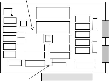
Set addresses here
(SW1, SW2) |
(Diagram not to scale) |
|
|
16450/16550 |
|
|
|
|
|
|
CN1 |
J1 |
|
|
J7 |
Serial 1 |
|
|
16450/16550 |
|
|
J2 |
SW1 |
J4 |
SW2 |
|
J3 |
|
|||
Serial 1 |
|
Serial 2 |
|
|
|
|
|
J8 |
Serial 2 |
|
|
|
J5 Serial 1 |
|
|
|
|
J6 Serial 2 |
CN2 |
QUATECH INC. DS-102 |
|
IRQ2 IRQ3 IRQ4 IRQ5 IRQ6 IRQ7 |
|
|
|
|
|
||
Set IRQ levels here |
|
|
|
|
(J5, J6) |
|
|
|
|
Figure 2 --- Diagram of DS-102
Quatech DS-102 User's Manual |
3 |
III. ENABLING AND ADDRESSING PORTS
Setting the address
Each serial port on the DS-102 uses 8 consecutive I/O locations in the range of 0000 hex to 07FF hex. The base address of each port is set using a DIP switch pack on the DS-102. When setting the address selection switches, a switch in the "ON" position specifies that the corresponding address line must be a logic 0 for the port to be selected. Similarly, a switch in the "OFF" position forces the corresponding address line to be a logic 1 for the port to be selected.
Switch SW1 selects address lines A10 through A3 for Serial 1. Switch SW2 serves the same purpose with respect to Serial 2. The remaining address lines (A2, A1 and A0) are used by the UART to select the register being accessed. Address lines A11 through A15 must be at logic 0 for a port to be selected. The serial ports may be independently enabled or disabled by installing or removing a jumper from jumper pack J4.
Figure 3 shows how the switches on the DS-102 represent the address values for serial ports. This figure can be used to explain the examples shown in Figure 4.
A serial port's address is a 16-bit quantity that is most often expressed
in four hexadecimal (base 16) digits. A hex digit can hold a value from 0 to 15 (decimal), and is made up of four binary bits given weights of eight, four, two, and one, hence the maximum value of 8+4+2+1 = 15.
A common serial port address is 03F8 hex. The example below shows how the hex digits are broken down into binary bits.
Binary bits |
0 |
0 |
0 |
0 |
0 |
0 |
1 |
1 |
1 |
1 |
1 |
1 |
1 |
0 |
0 |
0 |
Bit weight |
8 |
4 |
2 |
1 |
8 |
4 |
2 |
1 |
8 |
4 |
2 |
1 |
8 |
4 |
2 |
1 |
Sum of bits |
0+0+0+0 |
0+0+2+1 |
8+4+2+1 |
8+0+0+0 |
||||||||||||
Hex digits |
|
0 |
|
|
|
|
3 |
|
|
F |
|
|
|
8 |
|
|
These address bits are set by the switches.
All other bits are considered to be zero.
0 0 0 0 |
0 0 1 1 |
1 1 1 1 |
1 0 0 0 |
|
|
|
|
|
|
|
|
Figure 3 --- Examination of a serial port base address
4 |
Quatech DS-102 User's Manual |
|
Switch on |
|
Switch off |
|
bit = 0 |
|
bit = 1 |
|
|
|
|
Serial 1 uses SW1 Serial 2 uses SW2
Factory default setting for Serial 1 --- 03F8 hex (COM1)
SW1
ON |
|
|
|
|
|
|
|
|
|
|
|
|
|
|
||
|
|
|
|
|
|
|
|
|
|
|
|
|
|
|
|
|
|
|
|
|
|
|
|
|
|
|
|
|
|
|
|
|
|
|
|
|
|
|
|
|
|
|
|
|
|
|
|
|
|
|
1 |
|
2 |
|
3 |
4 |
5 |
6 |
7 |
8 |
|
||||||
|
|
|
|
|
|
|
|
|
|
|
|
|
|
|
|
|
0 |
|
2 |
|
1 |
8 |
4 |
2 |
1 |
8 |
|
||||||
|
|
|
3 |
|
|
|
|
|
|
F |
|
|
8 |
|
||
Factory default setting for Serial 2 --- 02F8 hex (COM2)
SW2
ON |
|
|
|
|
|
|
|
|
|
|
|
|
|
|
||
|
|
|
|
|
|
|
|
|
|
|
|
|
|
|
|
|
|
|
|
|
|
|
|
|
|
|
|
|
|
|
|
|
|
|
|
|
|
|
|
|
|
|
|
|
|
|
|
|
|
|
1 |
|
2 |
|
3 |
4 |
5 |
6 |
7 |
8 |
|
||||||
|
|
|
|
|
|
|
|
|
|
|
|
|
|
|
|
|
0 |
|
2 |
|
0 |
8 |
4 |
2 |
1 |
8 |
|
||||||
|
|
|
2 |
|
|
|
|
|
|
F |
|
|
8 |
|
||
Example: 03E8 hex (typical for COM3)
ON |
|
|
|
|
|
|
|
|
|
|
|
|
|
|
||
|
|
|
|
|
|
|
|
|
|
|
|
|
|
|
|
|
|
|
|
|
|
|
|
|
|
|
|
|
|
|
|
|
|
|
|
|
|
|
|
|
|
|
|
|
|
|
|
|
|
|
1 |
|
2 |
|
3 |
4 |
5 |
6 |
7 |
8 |
|
||||||
|
|
|
|
|
|
|
|
|
|
|
|
|
|
|
|
|
0 |
|
2 |
|
1 |
8 |
4 |
2 |
0 |
8 |
|
||||||
|
|
|
3 |
|
|
|
|
|
|
E |
|
|
8 |
|
||
Example: 02E8 hex (typical for COM4)
ON
|
|
|
|
|
|
|
|
|
|
|
|
|
|
|
|
|
|
|
|
|
|
|
|
|
|
|
|
|
|
|
|
|
|
|
|
|
|
1 |
|
2 |
|
3 |
4 |
5 |
6 |
7 |
8 |
|
|
|||||||
|
|
|
|
|
|
|
|
|
|
|
|
|
|
|
|
|
|
|
0 |
|
2 |
|
0 |
8 |
4 |
2 |
0 |
8 |
|
|
|||||||
|
|
|
|
2 |
|
|
|
|
|
|
E |
|
|
8 |
|
|
||
|
|
|
|
|
|
|
|
|
|
|
|
|
|
|
|
|
|
|
|
|
|
|
|
|
|
|
|
|
|
|
|
|
|
|
|
|
|
Figure 4 --- Serial Port base I/O address selection switches
Quatech DS-102 User's Manual |
5 |
 Loading...