


 Loading...
Getting Started Guide Getting Started Guide Getting Started Guide
Quantum Scalar i500 Tape Library
i500 Scalar
6-01741-01
Scalar i500 Getting Started Guide, 6-01741-01, Ver. A, June 2007, Made in USA.
Quantum Corporation provides this publication “as is” without warranty of any kind, either express or implied, including but not limited to the implied warranties of merchantability or fitness for a particular purpose. Quantum Corporation may revise this publication from time to time without notice.
COPYRIGHT STATEMENT
Copyright 2007 by Quantum Corporation. All rights reserved.
Your right to copy this manual is limited by copyright law. Making copies or adaptations without prior written authorization of Quantum Corporation is prohibited by law and constitutes a punishable violation of the law.
TRADEMARK STATEMENT
Quantum, the Quantum logo, DLT, DLTtape, the DLTtape logo, and Scalar are all registered trademarks of Quantum Corporation. LTO and Ultrium are trademarks of HP, IBM, and Quantum in the USA and other countries.
All other trademarks are the property of their respective companies.

Table of Contents
Scalar i500 Getting Started Guide (English) . . . . . . . . . . . . . . . . . . . . . . . . . . . . . . . . . .5 Scalar i500 - Einführungshandbuch (German). . . . . . . . . . . . . . . . . . . . . . . . . . . . . . . .23 Guide de démarrage rapide de la bandothèque Scalar i500 (French). . . . . . . . . . . . . .41 Guía de inicio de Scalar i500 (Spanish). . . . . . . . . . . . . . . . . . . . . . . . . . . . . . . . . . . . .59
Руководство по началу работы с ленточной библиотекой Scalar i500
(Russian) . . . . . . . . . . . . . . . . . . . . . . . . . . . . . . . . . . . . . . . . . . . . . . . . . . . . . . . . . . . .77 Scalar i500 (Japanese). . . . . . . . . . . . . . . . . . . . . . . . . . . . . . . . . . . .95 Scalar i500 (Korean) . . . . . . . . . . . . . . . . . . . . . . . . . . . . . . . . . . . . . . . .113 Scalar i500 (Simplified Chinese). . . . . . . . . . . . . . . . . . . . . . . . . . . . . . . . . .131
Scalar i500 Getting Started Guide |
3 |
4 |
Scalar i500 Getting Started Guide |

Scalar i500 Getting Started Guide
The Scalar i500 Getting Started Guide provides an overview of the steps required to unpack, set up, and install the Scalar i500 library. For more detailed information on configuring and running your library as well as adding, removing, and replacing parts, see the Scalar i500 User’s Guide.
Release Notes are also available for this product. The Release Notes describe changes to your system or firmware since the last release, provide compatibility information, and discuss any known issues and workarounds.The Release Notes can be found at www.quantum.com. You can find a list of additional documentation in “About This Guide and Your Product” in the Scalar i500 User’s Guide.
 Note
Note
 WARNING
Before operating this product, read all instructions and warnings in this document and in the System, Safety, and Regulatory Information Guide. In addition, be sure to use this document in conjunction with the Scalar i500 User’s Guide.
WITHOUT TAPE DRIVES, TAPE CARTRIDGES, OR POWER SUPPLIES, A 5U CONTROL MODULE WEIGHS APPROXIMATELY 58 LBS. A 9U EXPANSION MODULE, WITHOUT TAPE DRIVES, TAPE CARTRIDGES, OR POWER SUPPLIES, EXCEEDS 65 LBS. TO AVOID SERIOUS INJURY, TWO PEOPLE ARE REQUIRED TO SAFELY LIFT THE MODULES INTO POSITION.
THE POWER OUTLET MUST BE AVAILABLE NEAR THE LIBRARY
WARNING |
AND MUST BE EASILY ACCESSIBLE. |
|
ALL LIBRARIES TALLER THAN 14U MUST BE INSTALLED IN A RACK WARNING HAVING A MAIN PROTECTIVE EARTHING (GROUNDING) TERMINAL,
AND POWER MUST BE SUPPLIED VIA AN INDUSTRIAL PLUG AND SOCKET-OUTLET AND/OR AN APPLIANCE COUPLER COMPLYING WITH IEC 60309 (OR AN EQUIVALENT NATIONAL STANDARD) AND HAVING A PROTECTIVE EARTH (GROUND) CONDUCTOR WITH A CROSS SECTIONAL AREA OF AT LEAST 1.5 MM2 (14 AWG).
TO ENSURE PROPER AIRFLOW AND ACCESS SPACE, ALLOW 60 CM (24 INCHES) IN THE FRONT AND BACK OF THE LIBRARY.
UNDER NO CIRCUMSTANCES SHOULD A RACK BE MOVED WHILE
WARNING |
LOADED WITH ONE OR MORE MODULES. |
|
Scalar i500 Getting Started Guide |
5 |

Step 1: Unpack the Library
1Unpack the library.
Following the unpacking instructions that came with the library, remove the library exterior packaging but leave the library in the bottom packaging tray.
Save all packing materials in case you need to move or ship the
CAUTION |
library in the future. |
|
2Check the contents of the package against the packing slip.
3Remove the interior packaging.
Be sure to remove the following items:
CAUTION
• The strap holding the robot in place. Release the velcro and unhook each end of the strap.
• All cardboard and foam surrounding the robot.
WITHOUT TAPE DRIVES, TAPE CARTRIDGES, OR POWER WARNING SUPPLIES, A 5U CONTROL MODULE WEIGHS APPROXIMATELY 58
LBS. A 9U EXPANSION MODULE, WITHOUT TAPE DRIVES, TAPE CARTRIDGES, OR POWER SUPPLIES, EXCEEDS 65 LBS. TO AVOID SERIOUS INJURY, TWO PEOPLE ARE REQUIRED TO SAFELY LIFT THE MODULES INTO POSITION.
4Remove the tape drives from the library.
For information about removing tape drives, see “Adding, Removing, and Replacing” in the Scalar i500 User’s Guide.
5Remove the power supplies from the library.
For information about removing power supplies, see “Adding, Removing, and Replacing” in the Scalar i500 User’s Guide.
6Choose an optimal location for the library.
To avoid damage, the library must be positioned in a stable location. See the System, Safety, and Regulatory Information Guide for more information on finding an optimal location for your library.
THE POWER OUTLET MUST BE AVAILABLE NEAR THE LIBRARY
WARNING |
AND MUST BE EASILY ACCESSIBLE. |
|
•Make sure a power source (only of the type marked on the product label) is available. For power requirements, see the ”Specifications” chapter in the Scalar i500 User’s Guide.
•Route any cables to avoid walking on them or pinching them with items placed on or against them. Pay particular attention to the cord at the wall receptacle and the point where the cord exits from the library. For recommended cabling procedures, see the Scalar i500 User’s Guide.
•Make sure that objects will not fall and liquids will not spill into the library’s chassis through openings.
6 |
Scalar i500 Getting Started Guide |

Step 2: Install the Rackmount Kit (Optional for 5U and 14U)
All Scalar i500 libraries taller than 14U must be installed in a rack.The rack secures the bottom module, and all other modules are then secured to the bottom module. Installing the modules into the rack requires at least two people. For instructions, see “Installing the Rackmount Kit” in the Scalar i500 User’s Guide.
Step 3: Install the Module(s)
There are two possible library configurations:
•Installing the Control Module as a Standalone Unit
•Installing a Multi-Module Library Configuration
Installing the Control Module as a Standalone Unit
1Open the library’s I/E station door and access door.
2Lift the control module and place it in the desired location.
3If you are placing the control module in a rack, use the rack ears to fasten the control module to the rack. For instructions, see “Installing the Rackmount Kit” in the Scalar i500 User’s Guide.
4Continue installation with Step 4: Install the Module Components on page 13.
Installing a Multi-Module Library Configuration
Follow these instructions if you are installing a new multi-module library, or if you are adding expansion modules to an existing library.
Required tools:
•Phillips #2 screwdriver, for removing and replacing the top cover plate
•T10 TORX screwdriver, for removing and replacing the bottom cover plate
There are no restrictions on where the control module can be installed in the library configuration. However, the recommended placement of the control module for library configurations up to 32U is on top of all installed 9U expansion modules. The recommended placement of the control module for 41U library configurations is on top of three 9U expansion modules and below the top expansion module.
|
|
|
|
Cover Plate |
|
|
|
|
|
|
|
|
Cover Plate |
Expansion Module |
|
|
|
|
|
|
|
Cover Plate |
CONTROL MODULE |
CONTROL MODULE |
|
|
|
|
|
|
Cover Plate |
CONTROL MODULE |
Expansion Module |
Expansion Module |
|
|
|
|
|
Cover Plate |
CONTROL MODULE |
Expansion Module |
Expansion Module |
Expansion Module |
|
|
|
|
|
CONTROL MODULE |
Expansion Module |
Expansion Module |
Expansion Module |
Expansion Module |
|
|
|
|
|
Cover Plate |
Cover Plate |
Cover Plate |
Cover Plate |
Cover Plate |
|
|
|
|
|
5U |
14U |
23U |
32U |
41U |
Scalar i500 Getting Started Guide |
7 |

1Park the robot assembly in the control module.
a.Open the I/E station and access doors of each module.
b.Using your hands, gently lift the robot assembly into the control module. The robot assembly should glide slowly and with some resistance.
Support the robot assembly by holding onto the broad metal X-axis
CAUTION |
plate. Lifting the robot by the thin metal rod will bend the rod. |
|
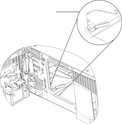
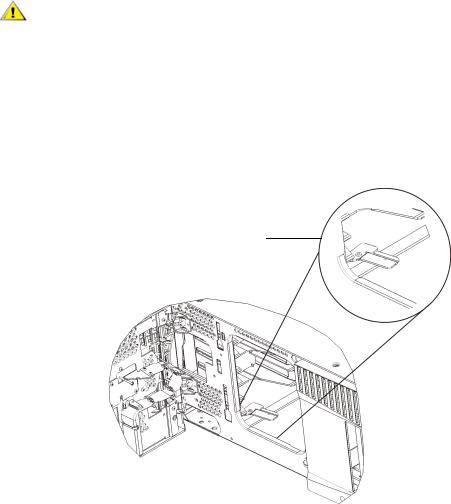
c.After raising the robot assembly to the approximate middle of the control module, hold it in place with one hand and, using your other hand, swivel the parking tab toward you. The metal parking tab is located at the bottom of column 1.
d.Gently release the robot assembly to rest on the parking tab.
Parking tab in “parked” position
2Remove top or bottom cover plates if necessary.
There should only be one top cover and one bottom cover plate in the final configuration. There should be no cover plates in between modules.
8 |
Scalar i500 Getting Started Guide |

3Install the expansion module(s).
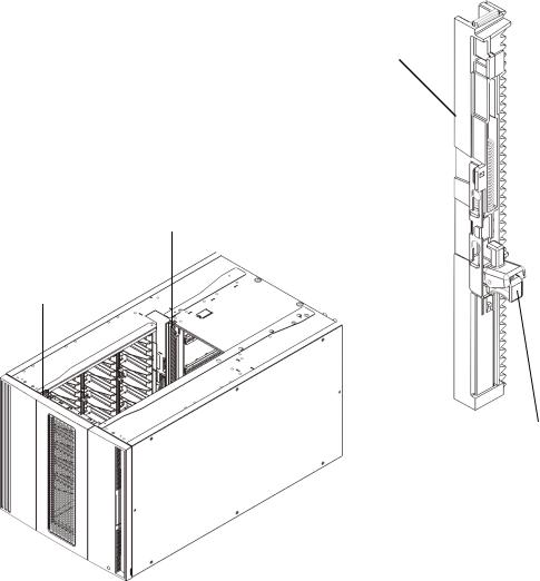
a.Open the 9U expansion module’s access door and raise the guide pin by pulling it up and turning it slightly as if it were a screw. Otherwise, the guide pin may scratch the front doors of the module on which you are stacking.
Guide pin |
Thumbscrew |
b.Lift the new expansion module and, from the front of the library, place it in the desired location.
c.If stacking the expansion module on top of another module, lower the module’s guide pin (located at the base of the front of the module) by turning it and pushing it down. Then secure the two modules together by tightening the two thumbscrews at the base of the front of the module and the two thumbscrews located at the base of the back of the module.
d.Tighten all thumbscrews located at the base of the front and back of the modules.
e.Fasten the module to the rack with rack ears. For instructions, see “Installing the Rackmount Kit” in the Scalar i500 User’s Guide.
Scalar i500 Getting Started Guide |
9 |

f.If stacking the expansion module on top of another module, engage the Y-rails of the new module in your library configuration. Ensure that the Y-rails are properly aligned and the thumbscrews are tightened.
Y-rail (this end up)
Rear Y-rail
Front Y-rail
Squeeze here to release
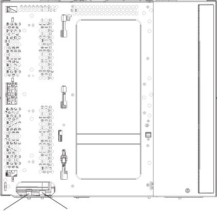
g.From the front of the library, open the I/E station and access doors of the expansion module. Squeeze the handle of the Y-rail release mechanism, lift it out of its locked position, and slide it downward as far as it will go.
h.From the back of the library, find the rear Y-rail release mechanism, which is located in the interior of the right side of the module. Squeeze the handle of the Y-rail release mechanism, lift it out of its locked position, and slide it downward as far as it will go.
10 |
Scalar i500 Getting Started Guide |
Check to make sure that there is no gap between the top and bottom CAUTION Y-rails on both the front and back of the library. If a gap exists, the
library cannot mechanically initialize.
Doing this aligns the Y-rails with the Y-rails of the module beneath it.
Y-rail in unlocked, functional position
i.Repeat these steps for each expansion module you are installing.
4Install the control module.
a.Open the control module’s I/E station door and access door.
b.Lift the control module and place it in the desired location.
c.If stacking the control module on top of another module, secure the two modules together by tightening the two thumbscrews at the base of the front1 of the module and the two thumbscrews located at the base of the back of the module. Then lower the module’s guide pin (located at the base of the front of the module) by turning it and pushing it down.
d.Tighten all thumbscrews located at the base of the front and back of the modules.
e.Use the rack ears to fasten the control module to the rack. For instructions, see “Installing the Rackmount Kit” in the Scalar i500 User’s Guide.
5Unpark the robot assembly.
a.Gently raise the robot assembly so that it no longer rests on the parking tab.
Support the robot assembly by holding onto the broad metal X-axis
CAUTION |
plate. Lifting the robot by the thin metal rod will bend the rod. |
|
Scalar i500 Getting Started Guide |
11 |
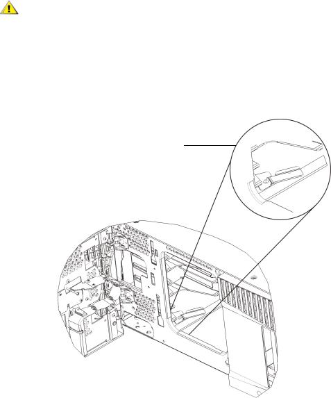
b.With your free hand, swivel the parking tab away from you until it is removed completely from the interior of the module. When replaced correctly, the parking tab will not accidentally swivel into the path of the robot.
c.Gently release the robot assembly. It will lower to the bottom module of the library.
Parking tab in “unparked” position
12 |
Scalar i500 Getting Started Guide |

Step 4: Install the Module Components
For instructions on any of the following steps, see “Adding, Removing, and Replacing” in the Scalar i500 User’s Guide.
1If not already installed, install the library control blade (LCB) in the control module.
2Install the tape drives.
3Install the power supplies.
4Install the Fibre Channel (FC) I/O blade (if required and not already installed).
5Close the library’s I/E station door and access door.
Step 5: Connect the Tape Drive Cables
Follow the instructions below for the type(s) of tape drives installed in your library. The instruction sets are:
•Connecting Parallel SCSI Cables
•Connecting Fibre Channel Cables Directly to Host or Switch
•Connecting Fibre Channel Cables Through an I/O Blade
•Connecting Serial Attached SCSI (SAS) Cables
A library can have any combination of SCSI, FC, and SAS drives, connected directly to hosts or through I/ O blades. You may need to follow more than one set of instructions below. For more detailed instructions, see the Scalar i500 User’s Guide.
Scalar i500 Getting Started Guide |
13 |

Connecting Parallel SCSI Cables
There are two recommended ways to cable SCSI tape drives: two tape drives per SCSI bus or one tape drive per SCSI bus.
To connect two tape drives per SCSI bus:
1Connect one end of the SCSI cable to the top SCSI port of the bottom tape drive. Then connect the other end of the cable to the bottom SCSI port of the tape drive above. To avoid possible performance issues, do not connect more than two tape drives per SCSI bus.
2Use another SCSI cable to connect the bottom tape drive of the SCSI bus to your host system.
3Use a SCSI terminator to terminate the top tape drive of the SCSI bus.
To connect one tape drive per SCSI bus:
4Use a SCSI cable to connect the bottom port of the tape drive to your host system.
5Attach a SCSI terminator to terminate the top port of the tape drive.
The library supports a maximum cable length of 12 meters (including
CAUTION |
internal wiring) for Ultra 160 SCSI and Ultra 320 SCSI cables. |
|
14 |
Scalar i500 Getting Started Guide |
Connecting Fibre Channel Cables Directly to Host or Switch
For each tape drive:
1Connect one end of a Fibre Channel cable to the Fibre Channel port on the tape drive.
2Connect the other end of the cable to your host or switch.
Scalar i500 Getting Started Guide |
15 |
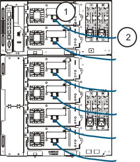
Connecting Fibre Channel Cables Through an I/O Blade
For each tape drive:
1Connect one end of a Fibre Channel cable to the Fibre Channel port on the tape drive.
2Connect the other end of the cable to an initiator port (lower ports 3 – 6) on the nearest Fibre Channel I/O blade.
For each Fibre Channel I/O blade:
3Connect one end of a Fibre Channel cable to one of the target ports (upper ports 1 and 2) on the Fibre Channel I/O blade.
4Connect the other end of the cable to your host or switch.
16 |
Scalar i500 Getting Started Guide |
Connecting Serial Attached SCSI (SAS) Cables
For each tape drive:
1Connect one end of a SAS cable to the SAS port on the tape drive.
2Connect the other end of the cable directly to the host.
The library supports SAS host cable lengths meeting the standard
CAUTION |
SAS specification. |
|
Scalar i500 Getting Started Guide |
17 |

Step 6: Connect the Library Cables
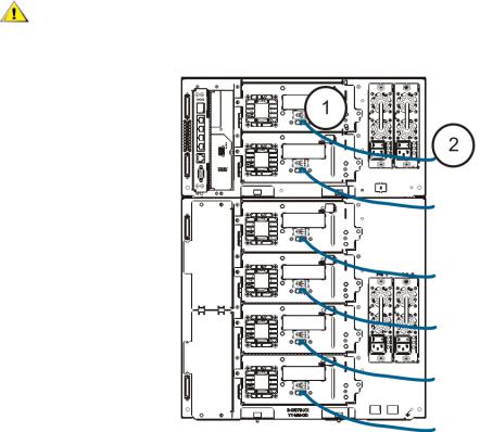
1Connect module cables and module terminators.
All libraries must use module terminators. Libraries that consist of multiple modules must use module- to-module cables.
The module terminator is not the same as a SCSI terminator. Using a SCSI
CAUTION |
terminator instead of a module terminator can damage the library. |
|
a.Using the module-to-module cables from the accessory kit, connect each module to the one above it. Connect one end of the cable to the bottom module. Then connect the other end of the cable to the module above it.
b.Using the module terminators from the accessory kit, terminate the topmost and bottommost modules.
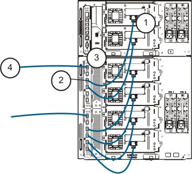
2Connect the Ethernet cable.
Connect an Ethernet cable to the top Gigabit Ethernet port on the library control blade (LCB) for remote access to the library via the web client. (Ethernet cable not supplied.)
3Connect the module Ethernet cables (if required).
Perform this step if your library contains at least one Fibre Channel I/O blade.
Use Ethernet cables to connect the LCB in the library control module to each expansion module that contains a Fibre Channel I/O blade. For each Fibre Channel I/O blade installed in an expansion module:
a.Connect one end of the Ethernet cable to any of the four middle Ethernet ports on the LCB Ethernet hub. (The uppermost port is for remote access to the library via the web client, and the bottommost port is for service access.)
b.Connect the other end of the cable to the appropriate port on the 9U Expansion Module. If the Fibre Channel I/O blade is installed in the upper bay, use the port labelled "UPPER." If the Fibre Channel I/O blade is installed in the lower bay, use the port labelled "LOWER."
18 |
Scalar i500 Getting Started Guide |

4Connect the power cords.
At least one power supply is required for each module that contains tape drives.
For each power supply, connect one end of the power cord to the power supply. Then connect the other end to a nearby grounded AC power source (of the type marked on the product label).
Step 7: Using the Library For the First Time
1Power on the library.
a.Turn on the rear power switch of each of the power supplies.
b.Press the power switch on the front of the library once.
c.Power up the host system.
2Verify communication with all devices on the bus.
3Configure the library.
When you first power on the library, the operator panel displays the Setup Wizard. You must start using the Setup Wizard on the operator panel. After performing initial configuration, you can continue to use the Startup Wizard on the operator panel or use the web client. It is recommended that you use the web client after basic initial configuration because there are many more options available to you on the web client.
Note |
You may skip initial configuration, or exit partway through and come back. |
||
If you do this, the settings you do not configure will be assigned default |
|||
|
|||
|
settings until you change them. Default settings: |
||
|
- DCHP enabled |
||
|
- 6 |
I/E station slots |
|
|
- 0 |
Cleaning cartridge slots |
|
- The number of partitions equals the number of tape drive interface types the library contains (SCSI, FC, or SAS).
Scalar i500 Getting Started Guide |
19 |
The recommended procedure for using the Setup Wizard for the initial configuration is as follows:
a.Turn on the library and begin using the Setup Wizard on the operator panel.
b.The Setup Wizard prompts you to enter the network settings that allow the web client to access the library. Be sure to complete this step.
c.When the Setup Wizard screen text prompts you to choose Local or Remote, choose
Remote.
d.Log out of the operator panel.
e.Using the default administrative account, log in to the web client. Type admin in the User Name text box and password in the Password text box.
f.Complete the Setup Wizard screens on the web client interface. The final Setup Wizard screen will prompt you to apply your settings.
When you have completed the Setup Wizard, the Library Configuration report appears on the web client. The Library Configuration report provides information on the library’s tape drives, partitions, I/E stations, storage slots, cleaning slots, and loaded media.
You can configure network settings, set date and time, create user accounts, configure Import/Export (I/E) slots, and perform other tasks that allow you to begin using the library. If you need to license additional storage slots, contact technical support for license keys to activate the additional slots. For contact information, see “About This Guide and Your Product” in the Scalar i500 User’s Guide.
For instructions on configuring the library, see “Configuring Your Library” in the Scalar i500 User’s Guide. See also the library’s online Help. To access the online Help system, click the Help icon at the top right of the web client or operator panel user interface.
4Load tape cartridges into the library.
For instructions on importing and bulkloading tape cartridges, see ”Running the Library” in the Scalar i500 User’s Guide.
5Assign tape drives to partitions (if using the I/E commands).
When manual cartridge assignment is enabled (the default setting), you cannot import cartridges using the I/E commands until you have assigned them to a partition. The Assign IE screen on the operator panel will prompt you to assign them to a partition.
If manual cartridge assignment is disabled, the Assign IE screen does not appear and the cartidges in the I/E station are visible to all partitions, as well as the system partition, and can be used by any partition. For more information, see the Scalar i500 User’s Guide.
6Connect to the host application.
Set up the connection to the library host application. If your host application inventories the location of each tape cartridge in the library, open the host application and perform a reinventory to sync the logical inventory with the physical inventory of the library.
For instructions, see your host application documentation.
7Register the library.
For more information about registering the library, see “Configuring the Library” in the Scalar i500 User’s Guide.
20 |
Scalar i500 Getting Started Guide |
Step 8: Run the Library
You are now ready to start using your library. For information about using your library, see “Running the Library” in the Scalar i500 User’s Guide. See also the library’s online Help. To access the online Help system, click the Help icon at the top right of the web client or operator panel user interface.
 Note
Note
 Note
Note
You can download the latest drivers from: www.quantum.com.
The maximum number of expansion modules supported in a library depends on the level of firmware the library is running. The latest firmware must be installed on the library if you are upgrading from a 5U, 14U, 23U configuration to a larger configuration. The latest firmware can be found at www.quantum.com.
Scalar i500 Getting Started Guide |
21 |
22 |
Scalar i500 Getting Started Guide |

Scalar i500 - Einführungshandbuch
Das Scalar i500 - Einführungshandbuch bietet eine Übersicht über die erforderlichen Schritte, um die Scalar i500 Bibliothek auszupacken, einzustellen und zu installieren. Weitere Informationen über die Konfiguration und das Ausführen Ihrer Bibliothek sowie das Hinzufügen, Entfernen und Ersetzen von Teilen finden Sie im
Scalar i500 Benutzerhandbuch.
Anmerkungen zu Versionen sind auch für dieses Produkt verfügbar. Die Anmerkungen zu Versionen beschreiben Änderungen zu Ihrem System oder Firmware seit der letzten Version, geben Kompatibilitätsauskunft und erörtern alle bekannten Probleme und Behelfslösungen.Die Anmerkungen zu Versionen können unter www.quantum.com gefunden werden. Sie können eine Liste der zusätzlichen Dokumentation im Scalar i500 Benutzerhandbuch unter "Zu diesem Handbuch und Ihrem Produkt" finden.
 Anmerkung
 WARNUNG
Lesen Sie vor der Inbetriebnahme dieses Produkts alle Anleitungen und Warnungen in diesem Dokument und im System-, Sicherheitsund BetriebsbestimmungenHandbuch. Seien Sie außerdem sicher, dieses Dokument in Verbindung mit dem
Scalar i500-Benutzerhandbuch zu verwenden.
OHNE BANDLAUFWERKE, BANDKASSETTEN ODER NETZTEILE WIEGT EIN 5U-STEUERMODUL ETWA 26 KG. EIN 9UERWEITERUNGSMODUL WIEGT OHNE BANDLAUFWERKE, BANDKASSETTEN ODER NETZTEILE MEHR ALS 29 KG. UM ERNSTHAFTE VERLETZUNG ZU VERMEIDEN, SIND ZWEI PERSONEN ERFORDERLICH, UM DIE MODULE SICHER IN DIE POSITION ZU HEBEN.
DIE STECKDOSE MUSS IN DER NÄHE DER BIBLIOTHEK
WARNUNG |
VERFÜGBAR UND LEICHT ZUGÄNGLICH SEIN. |
|
ALLE BIBLIOTHEKEN, DIE HÖHER ALS 14U SIND, MÜSSEN IN EINEM WARNUNG RACK INSTALLIERT WERDEN, DAS ÜBER EIN HAUPTSICHERUNGS-
TERMINAL (ERDUNG) VERFÜGT. ZUDEM MUSS DIE STROMVERSORGUNG ÜBER EINE INDUSTRIELLE STECKDOSE UND EINE STECKDOSE UND/ODER EINE STECKVORRICHTUNG ERFOLGEN, DIE IEC 60309 (ODER EINEM ENTSPRECHENDEN LANDESSTANDARD) ENTSPRICHT, UND ÜBER EINEN SCHUTZERDLEITER (ERDUNG) MIT EINEM QUERSCHNITT VON MINDESTENS 1,5 MM2 (14 AWG) VERFÜGEN.
LASSEN SIE AN DER VORDERUND HINTERSEITE DER BIBLIOTHEK EINEN RAUM VON JEWEILS 60 CM (24 ZOLL) FREI, DAMIT DIE LUFT GUT ZIRKULIEREN KANN UND EIN PROBLEMLOSER ZUGRIFF AUF DIE BIBLIOTHEK GEWÄHRLEISTET IST.
KEINESFALLS SOLLTE EIN RACK BEWEGT WERDEN, WÄHREND ES
WARNUNG |
MIT EINEM ODER MEHREREN MODULEN GELADEN IST. |
|
Scalar i500 - Einführungshandbuch |
23 |

Schritt 1: Auspacken der Bibliothek
1Packen Sie die Bibliothek aus.
Entfernen Sie entsprechend der Auspackanleitung, die mit der Bibliothek geliefert wurde, die Außenverpackung der Bibliothek, aber lassen Sie die Bibliothek im untersten Verpackungseinsatz.
Bewahren Sie alle Verpackungsmaterialien auf, falls Sie die Bibliothek
VORSICHT |
in der Zukunft entfernen oder versenden müssen. |
|
2Überprüfen Sie den Inhalt der Verpackung, damit dieser nicht in der Verpackung verrutschen kann.
3Entfernen Sie die Innenverpackung.
Stellen Sie sicher, dass Sie die folgenden Artikel entfernen:
VORSICHT
• Der Riemen, der die Robotik an seinem Platz hält. Lösen Sie den Klettverschluss und haken Sie jedes Ende des Riemens aus.
• Der ganze Karton und Schaumstoff, die die Robotik umgeben.
OHNE BANDLAUFWERKE, BANDKASSETTEN ODER NETZTEILE WIEGT WARNUNG EIN 5U-STEUERMODUL ETWA 26 KG. EIN 9U-ERWEITERUNGSMODUL
WIEGT OHNE BANDLAUFWERKE, BANDKASSETTEN ODER NETZTEILE MEHR ALS 29 KG. UM ERNSTHAFTE VERLETZUNG ZU VERMEIDEN, SIND ZWEI PERSONEN ERFORDERLICH, UM DIE MODULE SICHER IN DIE POSITION ZU HEBEN.
4Entfernen Sie die Bandlaufwerke aus der Bibliothek.
Informationen über die Entfernung von Bandlaufwerken, finden Sie im Scalar i500 Benutzerhandbuch unter "Hinzufügen, Entfernen und Ersetzen".
5Entfernen Sie die Netzteile aus der Bibliothek.
Informationen über das Entfernen von Netzteilen finden Sie im Scalar i500 Benutzerhandbuch unter "Hinzufügen, Entfernen und Ersetzen".
6Wählen Sie einen optimalen Speicherort für die Bibliothek.
Um Schäden zu vermeiden, muss die Bibliothek an einem stabilen Speicherort aufgestellt werden. Weitere Informationen zum Finden eines optimalen Speicherortes für Ihre Bibliothek finden Sie im
System-, Sicherheits-, und Betriebsbestimmungen-Handbuch .
DIE STECKDOSE MUSS IN DER NÄHE DER BIBLIOTHEK VERFÜGBAR
WARNUNG |
UND LEICHT ZUGÄNGLICH SEIN. |
|
•Stellen Sie sicher, dass eine Stromquelle (nur des auf dem Produktetikett gekennzeichneten Typs) verfügbar ist. Stromvoraussetzungen finden Sie im Kapitel "Technische Daten" im Scalar i500 Benutzerhandbuch.
•Kennzeichnen Sie alle Kabel, um das Betreten oder Einklemmen mit Gegenständen, die auf oder gegen sie gelegt sind, zu vermeiden. Achten Sie besonders auf das Kabel an der Wandsteckdose und die Stelle, an der das Kabel aus der Bibliothek austritt. Empfohlene Verkabelungsverfahren finden Sie im Scalar i500 Benutzerhandbuch.
•Stellen Sie sicher, dass keine Gegenstände herunterfallen und keine Flüssigkeiten ins Gehäuse der Bibliothek durch Öffnungen gegossen werden.
24 |
Scalar i500 - Einführungshandbuch |

Schritt 2: Installation des Rackmount-Montagesatzes (optional für 5U und 14U)
Alle Scalar i500-Bibliotheken, die höher als 14U sind, müssen in einem Rack installiert werden. Das Rack sichert das unterste Modul, und alle anderen Module werden dann am untersten Modul gesichert. Die Installation der Module ins Rack erfordert mindestens zwei Personen. Anweisungen finden Sie im Scalar i500 Benutzerhandbuch unter "Installation des Rackmount-Montagesatzes".
Schritt 3: Installation des/der Moduls/Module
Es gibt zwei mögliche Bibliothekskonfigurationen:
•Installation des Steuermoduls als eine eigenständige Einheit
•Installation einer Multimodul-Bibliothekskonfiguration
Installation des Steuermoduls als eine eigenständige Einheit
1Öffnen Sie die I/E-Station- und Zugriffstür der Bibliothek.
2Heben Sie das Steuermodul und legen Sie es in den gewünschten Speicherort.
3Wenn Sie das Steuermodul in ein Rack legen, verwenden Sie die Rack-Laschen, um das Steuermodul am Rack zu befestigen. Anweisungen finden Sie im Scalar i500-Benutzerhandbuch unter "Installation des Rackmount-Montagesatzes".
4Fahren Sie die Installation mit Schritt 4: Installation der Modulkomponenten auf der Seite 31 fort.
Installation einer Multimodul-Bibliothekskonfiguration
Folgen Sie diesen Anweisungen, wenn Sie eine neue Multimodul-Bibliothek installieren, oder wenn Sie Erweiterungsmodule zu einer vorhandenen Bibliothek hinzufügen.
Erforderliche Hilfsprogramme:
•Kreuzschlitzschaubenzieher #2, um die obere Abdeckplatte zu entfernen und zu ersetzen.
•T10 TORX-Schraubenzieher, um die untere Abdeckplatte zu entfernen und zu ersetzen.
Es gibt keine Beschränkungen, wo das Steuermodul in der Bibliothekskonfiguration installiert werden kann. Jedoch wird empfohlen, das Steuermodul für Bibliothekskonfigurationen bis zu 32U über allen installierten 9U-Erweiterungsmodulen zu platzieren. Es wird empfohlen, das Steuermodul für 41UBibiliothekskonfigurationen über den drei 9U-Erweiterungsmodulen und unter dem obersten Erweiterungsmodul zu platzieren.
|
|
|
|
Abdeckplatte |
|
|
|
|
|
|
|
|
Abdeckplatte |
Erweiterungsmodul |
|
|
|
|
|
|
|
Abdeckplatte |
STEUERMODUL |
STEUERMODUL |
|
|
|
|
|
|
Abdeckplatte |
STEUERMODUL |
Erweiterungsmodul |
Erweiterungsmodul |
|
|
|
|
|
Abdeckplatte |
STEUERMODUL |
Erweiterungsmodul |
Erweiterungsmodul |
Erweiterungsmodul |
|
|
|
|
|
STEUERMODUL |
Erweiterungsmodul |
Erweiterungsmodul |
Erweiterungsmodul |
Erweiterungsmodule |
|
|
|
|
|
Abdeckplatte |
Abdeckplatte |
Abdeckplatte |
Abdeckplatte |
Abdeckplatte |
|
|
|
|
|
5U |
14U |
23U |
32U |
41U |
Scalar i500 - Einführungshandbuch |
25 |
1Stellen Sie die Robotikeinheit im Steuermodul ab.
a.Öffnen Sie die I/E-Station und Zugriffstüren jedes Moduls.
b.Heben Sie die Robotikeinheit behutsam mit Ihren Händen in das Steuermodul. Die Robotikeinheit sollte langsam und mit etwas Widerstand gleiten.
Stützen Sie die Robotikeinheit, indem Sie die breite, metallene Platte der VORSICHT X-Achse festhalten. Wenn die Robotik durch die dünne Metallstange
gehoben wird, wird die Stange gebogen.
c.Nachdem die Robotikeinheit bis ungefähr zur Mitte des Steuermoduls angehoben wurde, halten Sie sie mit einer Hand an dieser Stelle fest und drehen Sie mit der anderen Hand das Feststellregister auf sich zu. Das metallene Feststellregister befindet sich am unteren Ende der Säule 1.
d.Lösen Sie behutsam die Robotikeinheit, damit sie auf dem Feststellregister liegen kann.
Feststellregister in
"geparkter" Position
2Entfernen Sie nötigenfalls die obere oder untere Abdeckplatte.
Es sollte nur eine obere und eine untere Abdeckplatte bei der Endkonfiguration vorhanden sein. Zwischen den Modulen sollten keine Abdeckplatten vorhanden sein.
26 |
Scalar i500 - Einführungshandbuch |
3Installieren Sie das(die) Erweiterungsmodul(e).
a.Öffnen Sie die Zugriffstür des 9U-Erweiterungsmoduls und heben Sie den Führungsstift an, indem Sie ihn herausziehen und wie eine Schraube etwas drehen. Andernfalls kann der Führungsstift die Vordertüren des Moduls verkratzen, auf dem Sie stapeln.
Führungsstift Rändelschraube
b.Heben Sie das neue Erweiterungsmodul an und legen Sie es auf der Vorderseite der Bibliothek in den gewünschten Speicherort.
c.Wenn das Erweiterungsmodul über ein anderes Modul gestapelt wird, senken Sie den Führungsstift des Moduls (befindet sich am Boden der Vorderseite des Moduls), indem Sie ihn drehen und nach unten drücken. Dann befestigen Sie die zwei Module, indem Sie die zwei Rändelschrauben am Boden der Vorderseite des Moduls und die zwei Rändelschrauben am Boden der Hinterseite des Moduls festziehen.
d.Ziehen Sie alle Rändelschrauben am Boden der Vorderund Rückseite der Module fest.
e.Befestigen Sie das Modul am Rack mit Rack-Laschen. Anweisungen finden Sie im Scalar i500Benutzerhandbuch unter "Installation des Rackmount-Montagesatzes".
Scalar i500 - Einführungshandbuch |
27 |
f.Wenn das Erweiterungsmodul über ein anderes Modul gestapelt wird, klinken Sie Y-Schienen des neuen Moduls in Ihrer Bibliothekskonfiguration ein. Stellen Sie sicher, dass die Y-Schienen richtig ausgerichtet und die Rändelschrauben festgezogen sind.
Y-Schiene (dieses Ende
nach oben)
Hintere Y-Schiene
Vordere Y-
Schiene
Zum Lösen hier drücken
g.Öffnen Sie die I/E-Station und Zugriffstüren des Erweiterungsmoduls auf der Vorderseite der Bibliothek. Drücken Sie den Griff des Entriegelungsmechanismus der Y-Schiene, heben Sie ihn aus seiner verriegelten Position und lassen Sie ihn soweit wie möglich nach unten gleiten.
h.Auf der Rückseite der Bibliothek finden Sie den Entriegelungsmechanismus der Y-Schiene, der sich im Inneren der rechten Modulseite befindet. Drücken Sie den Griff des Entriegelungsmechanismus der Y-Schiene, heben Sie ihn aus seiner verriegelten Position und lassen Sie ihn soweit wie möglich nach unten gleiten.
28 |
Scalar i500 - Einführungshandbuch |

Überprüfen Sie, um sicherzustellen, dass es keine Lücke zwischen VORSICHT den oberen und unteren Y-Schienen sowohl auf der Vorderals auch
auf der Rückseite der Bibliothek gibt. Wenn eine Lücke besteht, kann die Bibliothek nicht mechanisch initialisieren.
Dadurch werden die Y-Schienen nach den Y-Schienen des unteren Moduls ausgerichtet.
Y-Schiene in entriegelter, funktionsfähiger Position
i.Wiederholen Sie diese Schritte für jedes Erweiterungsmodul, das Sie installieren.
4Installieren Sie das Steuermodul.
a.Öffnen Sie die I/E-Station- und Zugriffstür des Steuermoduls.
b.Heben Sie das Steuermodul und legen Sie es in den gewünschten Speicherort.
c.Wenn das Steuermodul über ein anderes Modul gestapelt wird, befestigen Sie die zwei Module, indem Sie die zwei Rändelschrauben am Boden der Vorderseite 1 und die zwei Rändelschrauben am Boden der Rückseite des Moduls festziehen. Dann senken Sie den Führungsstift des Moduls (befindet sich am Boden der Vorderseite des Moduls), indem Sie ihn drehen und herunterdrücken.
d.Ziehen Sie alle Rändelschrauben am Boden der Vorderund Rückseite der Module fest.
e.Verwenden Sie die Rack-Laschen, um das Steuermodul am Rack zu befestigen. Anweisungen finden Sie im Scalar i500-Benutzerhandbuch unter "Installation des Rackmount-Montagesatzes".
5Nehmen Sie die Robotikeinheit auf.
Scalar i500 - Einführungshandbuch |
29 |
a. Heben Sie die Robotikeinheit behutsam an, so dass sie nicht mehr auf dem Feststellregister ruht.
Stützen Sie die Robotikeinheit, indem Sie die breite, metallene Platte der VORSICHT X-Achse festhalten. Wenn die Robotik durch die dünne Metallstange
gehoben wird, wird die Stange gebogen.
b.Drehen Sie das Feststellregister mit der freien Hand von sich weg, bis es völlig aus dem Inneren des Moduls entfernt ist. Wenn das Feststellregister richtig ersetzt wurde, wird es sich absichtlich in die Laufbahn der Robotik drehen.
c.Lösen Sie die Robotikeinheit behutsam. Sie wird zum untersten Modul der Bibliothek sinken.
Feststellregister in "ungeparkter" Position
30 |
Scalar i500 - Einführungshandbuch |
Loading...