


QT600

Qt 600
MANUAL 1.0
QUANTUM
tm
ENGLISH
DEUTSCH
FRANÇAIS
ITALIANO
ESPAÑOL
superior bass amplification

IMPORTANT SAFETY INSTRUCTIONS
BEFORE CONNECTING, READ INSTRUCTIONS
• Read all of these instructions!
• Save these instructions for later use!
• Follow all warnings and instructions marked on the product!
• Do not use this product near water, i.e. bathtub, sink, swimming pool, wet basement,
etc.
• Do not place this product on an unstable cart, stand or table. The product may fall,
causing serious damage to the product or to persons!
• Slots and openings in the cabinet and the back or bottom are provided for ventilati-
on; to ensure reliable operation of the product and to protect it from overheating,
these openings must not be blocked or covered. This product should not be placed
in a built-in installation unless proper ventilation is provided.
• This product should not be placed near a source of heat such as a stove, radiator, or
another heat producing amplifier.
• Use only the supplied power supply or power cord. If you are not sure of the type of
power available, consult your dealer or local power company.
• Do not allow anything to rest on the power cord. Do not locate this product where
persons will walk on the cord.
• Never break off the ground pin on the power supply cord.
• Power supply cords should always be handled carefully. Periodically check cords for
cuts or sign of stress, especially at the plug and the point where the cord exits the
unit.
• The power supply cord should be unplugged when the unit is to be unused for long
periods of time.
• If this product is to be mounted in an equipment rack, rear support should be provided.
• This product should be used only with a cart or stand that is recommended by
Hughes & Kettner.
• Never push objects of any kind into this product through cabinet slots as they may
touch dangerous voltage points or short out parts that could result in risk of fire or
electric shock. Never spill liquid of any kind on the product.
• Do not attempt to service this product yourself, as opening or removing covers may
expose you to dangerous voltage points or other risks. Refer all servicing to qualified
service personnel.
• Clean only with dry cloth.
• Do not defeat the safety purpose of the polarized or grounding-type plug. A polari-
zed plug has two blades with one wider than the other. A grounding type plug has
two blades and a third grounding prong. The wide blade or the third prong are
provided for the safety. If the provided plug does not fit into your outlet, consult an
electrician for replacement of the obsolete outlet.
• Unplug this product from the wall outlet and refer servicing to qualified service per-
sonnel under the following conditions:
• When the power cord or plug is damaged or frayed.
• If liquid has been spilled into the product.
• If the product has been exposed to rain or water.
• If the product does not operate normally when the operating instructions are followed.
• If the product has been dropped or the cabinet has been damaged.
• If the product exhibits a distinct change in performance, indicating a need of service!
• Adjust only these controls that are covered by the operating instructions since impro-
per adjustment of other controls may result in damage and will often require exten-
sive work by a qualified technician to restore the product to normal operation.
• Exposure to extremely high noise levels may cause a permanent hearing loss.
• Individuals vary considerably in susceptibility to noise induced hearing loss, but near-
ly everyone will lose some hearing if exposed to sufficiently intense noise for a suffi-
cient time. The U.S. Government´s Occupational Safety and Health Administration
(OSHA) has specified the following permissible noise level exposures:
Duration Per Day In Hours Sound LeveldBA, Slow Response
890
692
495
397
2 100
1
1
/
2
102
1 105
1
/
2
110
1
/
4
or less 115
• According to OSHA, any exposure in excess of the above permissible limits could
result in some hearing loss.
• Ear plug protectors in the ear canals or over the ears must be worn when operating
this amplification system in order to prevent a permanent hearing loss if exposure is
in excess of the limits as set forth above. To ensure against potentially dangerous
exposure to high sound pressure levels, it is recommended that all persons exposed
to equipment capable of producing high sound pressure levels such as this amplifi-
cation system be protected by hearing protectors while this unit is in operation.
• Fuses: For continued protection against risk of fire. Replace with IEC127 (5 x 20 mm)
type and rated fuse for best performance only!.
TO PREVENT THE RISK OF FIRE AND SHOCK HAZARD, DO NOT EXPOSE THIS APPLIANCE TO
MOISTURE OR RAIN. DO NOT OPEN CASE; NO USER SERVICE-ABLE PARTS INSIDE.
REFER SERVICING TO QUALIFIED SERVICE PERSONNEL.
WICHTIGE SICHERHEITSHINWEISE!
BITTE VOR GEBRAUCH LESEN UND FÜR SPÄTEREN GEBRAUCH
AUFBEWAHREN!
• Das Gerät wurde von Hughes & Kettner gemäss IEC 60065 gebaut und hat das Werk in
sicherheitstechnisch einwandfreiem Zustand verlassen. Um diesen Zustand zu erhalten
und einen gefahrlosen Betrieb sicherzustellen, muss der Anwender die Hinweise und die
War nvermerke beachten, die in der Bedienungsanleitung enthalten sind. Das Gerät ent-
spricht der Schutzklasse I (schutzgeerdet).
• DIE SICHERHEIT, ZUVERLÄSSIGKEIT UND LEISTUNG DES GERÄTES WIRD VON
HUGHES & KETTNER NUR DANN GEWÄHRLEISTET, WENN:
• Montage, Erweiterung, Neueinstellung, Änderungen oder Reparaturen von
Hughes & Kettner oder von dazu ermächtigten Personen ausgeführt werden.
• die elektrische Installation des betreffenden Raumes den Anforderungen von
IEC (ANSI)-Festlegungen entspricht.
• das Gerät in Übereinstimmung mit der Gebrauchsanweisung verwendet wird.
WARNUNG:
• Wenn Abdeckungen geöffnet oder Gehäuseteile entfernt werden, ausser wenn dies von
Hand möglich ist, können Teile freigelegt werden, die Spannung führen.
• Wenn ein Öffnen des Gerätes erforderlich ist, muss das Gerät von allen Spannungs-
quellen getrennt sein. Berücksichtigen Sie dies vor dem Abgleich, vor einer Wartung, vor
einer Instandsetzung und vor einem Austausch von Teilen.
• Ein Abgleich, eine Wartung oder eine Reparatur am geöffneten Gerät unter Spannung
darf nur durch eine vom Hersteller autorisierte Fachkraft (nach VBG 4) geschehen, die
mit den verbundenen Gefahren vertraut ist.
• Lautsprecher-Ausgänge, die mit dem IEC 417/5036-Zeichen (Abb.1, s.unten) versehen
sind können berührungsgefährliche Spannungen führen. Deshalb vor dem Einschalten
des Gerätes Verbindung nur mit dem vom Hersteller empfohlenen Anschlusskabel zum
Lautsprecher herstellen.
• Alle Stecker an Verbindungskabeln müssen mit dem Gehäuse verschraubt oder verriegelt
sein, sofern möglich.
• Es dürfen nur IEC127 Sicherungen (5x 20 mm) des angegebenen Typs und der angege-
benen Nennstromstärke eingesetzt werden!
• Eine Verwendung von geflickten Sicherungen oder Kurzschliessen des Halters ist
unzulässig.
• Niemals die Schutzleiterverbindung unterbrechen.
• Oberflächen, die mit dem „HOT“-Zeichen (Abb.2, s.unten) versehen sind, Rückwände
oder Abdeckungen mit Kühlschlitzen, Kühlkörper und deren Abdeckungen, sowie Röhren
und deren Abdeckungen können im Betrieb erhöhte Temperaturen annehmen und soll-
ten deshalb nicht berührt werden.
• Hohe Lautstärkepegel können dauernde Gehörschäden verursachen. Vermeiden Sie
deshalb die direkte Nähe von Lautsprechern, die mit hohen Pegeln betrieben werden.
Verwenden Sie einen Gehörschutz bei dauernder Einwirkung hoher Pegel.
NETZANSCHLUSS:
• Das Gerät ist für Dauerbetrieb ausgelegt.
• Die eingestellte Betriebsspannung muss mit der örtlichen Netzspannung übereinstimmen.
• Achtung: Der Netzschalter des Gerätes muss in OFF-Position stehen, wenn das Netzkabel
angeschlossen wird.
• Der Anschluss an das Stromnetz erfolgt mit dem mitgelieferten Netzteil oder Netzkabel.
• Netzteil: Eine beschädigte Anschlussleitung kann nicht ersetzt werden. Das Netzteil darf
nicht mehr betrieben werden.
• Vermeiden Sie einen Anschluss an das Stromnetz in Verteilerdosen zusammen mit vielen
anderen Stromverbrauchern.
• Die Steckdose für die Stromversorgung muss nahe am Gerät angebracht und leicht
zugänglich sein.
AUFSTELLUNGSORT:
• Das Gerät sollte nur auf einer sauberen, waagerechten Arbeitsfläche stehen.
• Das Gerät darf während des Betriebs keinen Erschütterungen ausgesetzt sein.
• Feuchtigkeit und Staub sind nach Möglichkeit fernzuhalten.
• Das Gerät darf nicht in der Nähe von Wasser, Badewanne, Waschbecken, Küchenspüle,
Nassraum, Swimmingpool oder feuchten Räumen betrieben werden. Keine mit Flüssigkeit
gefüllten Gegenstände -Vase, Gläser, Flaschen etc. auf das Gerät stellen.
• Sorgen Sie für ausreichende Belüftung der Geräte.
• Eventuelle Ventilationsöffnungen dürfen niemals blockiert oder abgedeckt werden. Das
Gerät muss mindestens 20 cm von Wänden entfernt aufgestellt werden. Das Gerät darf
nur dann in ein Rack eingebaut werden, wenn für ausreichende Ventilation gesorgt ist
und die Einbauanweisungen des Herstellers eingehalten werden.
• Vermeiden Sie direkte Sonneneinstrahlung sowie die unmittelbare Nähe von Heizkörpern
und Heizstrahlern oder ähnlicher Geräte.
• Wenn das Gerät plötzlich von einem kalten an einen warmen Ort gebracht wird, kann sich
im Geräteinnern Kondensfeuchtigkeit bilden. Dies ist insbesondere bei Röhrengeräten zu
beachten. Vor dem Einschalten solange warten bis das Gerät Raumtemperatur angenom-
men hat.
• Zubehör: Das Gerät nicht auf einen instabilen Wagen, Ständer, Dreifuß, Untersatz oder
Tisch stellen. Wenn das Gerät herunterfällt, kann es Personenschäden verursachen und
selbst beschädigt werden. Verwenden Sie das Gerät nur mit einem vom Hersteller emp-
fohlenen oder zusammen mit dem Gerät verkauften Wagen, Rack, Ständer, Dreifuß oder
Untersatz. Bei der Aufstellung des Gerätes müssen die Anweisungen des Herstellers
befolgt und muss das vom Hersteller empfohlene Aufstellzubehör verwendet werden.
Eine Kombination aus Gerät und Gestell muss vorsichtigt bewegt werden. Plötzliches
Anhalten, übermässige Kraftanwendung und ungleichmässige Böden können das
Umkippen der Kombination aus Gerät und Gestell bewirken.
• Zusatzvorrichtungen: Verwenden Sie niemals Zusatzvorrichtungen, die nicht vom Hersteller
empfohlen wurden, weil dadurch Unfälle verursacht werden können
• Zum Schutz des Gerätes bei Gewitter oder wenn es längere Zeit nicht beaufsichtigt oder
benutzt wird, sollte der Netzstecker gezogen werden. Dies verhindert Schäden am Gerät
aufgrund von Blitzschlag und Spannungsstössen im Wechselstromnetz.
Abb.1 Abb.2

CONSEILS DE SECURITE IMPORTANTS!
PRIERE DE LIRE AVANT L’EMPLOI ET A CONSERVER POUR UTILISATION ULTERIEURE!
• L’appareil a été conçu par Hughes & Kettner selon la norme IEC
60065
et a
quitté l’entreprise dans un état irréprochable. Afin de conserver cet état et
d’assurer un fonctionnement sans danger de l’appareil nous conseillons à l’utili-
sateur la lecture des indications de sécurité contenues dans le mode d’emploi.
L’appareil est conforme à la classification I (mise à terre de protection).
• SURETE, FIABILITE ET EFFICACITE DE L’APPAREIL NE SONT GARANTIS PAR
HUGHES & KETTNER QUE SI:
• Montage, extension, nouveau réglage, modification ou réparation sont
effectués par Hughes & Kettner ou par toute personne autorisée par
Hughes & Kettner.
• L’installation électrique de la pièce concernée correspond aux normes IEC (ANSI).
• L’utilisation de l’appareil suit le mode d’emploi.
AVERTISSEMENT:
•A moins que cela ne soit manuellement possible, tout enlèvement ou ouverture
du boîtier peut entrainer la mise au jour de pieces sous tension.
• Si l’ouverture de l’appareil est nécessaire, celui-ci doit être coupé de chaque
source de courant. Ceci est à prendre en considération avant tout ajustement,
entretien, réparation ou changement de pieces.
• Ajustement, entretien ou réparation sur l’appareil ouvert et sous tension ne
peuvent être éffectués que par un spécialiste autorisé par le fabricant (selon
VBG4). Le spécialiste étant conscient des dangers liés à ce genre de
réparation.
• Les sorties de baffles qui portent le signe IEC 417/5036 (fig. 1, voir en bas)
peuvent être sous tension dangereuse. Avant de brancher l’appareil utiliser
uniquement le câble de raccordement conseillé par le fabricant pour
raccorder les baffles.
•Toutes les prises des câbles de raccordement doivent être, si possible, vissées
ou verrouillées sur le boîtier.
• Utilisez subsidiairement uniquement des fusibles de type et de puissance de
courant nominale donnés.
• L’utilisation de fusibles rafistolés ou court-circuites est inadmissible - seulement:
IEC127 (5x 20 mm).
• Ne jamais interrompre la connexion du circuit protecteur.
• Il est conseillé de ne pas toucher aux surfaces pourvues du signe „HOT“ (fig. 2,
voir en bas), aux parois arrières ou caches munis de fentes d’aération,
éléments d’aération et leurs caches ansi qu’aux tubes et leurs caches. Ces
éléments pouvant atteindre des températures élévées pendant l’utilisation de
l’appareil.
• Les Niveaux de puissance élévés peuvent entrainer des lésions auditives
durables. Evitez donc la proximité de haut-parleurs utilisés à haute puissance.
Lors de haute puissance continue utilisez une protection auditive.
BRANCHEMENT SUR LE SECTEUR:
• L’appareil est conçu pour une utilisation continue.
• La tension de fonctionnement doit concorder avec la tension secteur locale.
• Attention: L’interrupteur de secteur de l’appareil doit être sur la position OFF,
lorsque le câble de réseau est raccordé.
•Le raccordement au réseau éléctrique s’effectue avec l’adaptateur ou le
cordon d´alimentation livré avec l’appareil.
• Adaptateur: Un câble de raccordement abimé ne peut être remplacé.
L’adaptateur est inutilisable.
• Evitez un raccordement au réseau par des boîtes de distribution surchargées.
• La prise de courant doit être placée à proximité de l’appareil et facile à
atteindre.
LIEU D’INSTALLATION:
• L’appareil doit être placé sur une surface de travail propre et horizontale.
• L’appareil en marche ne doit en aucun cas subir des vibrations.
• Evitez dans la mesure du possible poussière et humidité.
• L’appareil ne doit pas être placé à proximité d’eau, de baignoire, lavabo,
évier, pièce d’eau, piscine ou dans une pièce humide. Ne placez aucun vase,
verre, bouteille ou tout objet rempli de liquide sur l’appareil.
• L’appareil doit être suffisamment aéré.
• Ne jamais recouvrir les ouvertures d’aération. L’appareil doit être placé à 20 cm
du mur au minimum. L’appareil peut être monté dans un Rack si une
ventilation suffisante est possible et si les conseils de montage du fabricant
sont suivis.
• Evitez les rayons de soleil et la proximité de radiateurs, chauffages etc.
• Une condensation d’eau peut se former dans l’appareil si celui-ci est transporté
brusquement d’un endroit froid à un endroit chaud. Ceci est particulièrement
important pour des appareils à tubes. Avant de brancher l’appareil attendre
qu’il ait la température ambiante.
• Accessoires: L’appareil ne doit être placé sur un chariot, support, trépied, bâti
ou table instable. Une chute de l’appareil peut entrainer aussi bien des
dommages corporels que techniques. Utilisez l’appareil uniquement avec un
chariot, Rack, support, trépied ou bâti conseillé par le fabricant ou vendu en
combinaison avec l’appareil. Les indications du fabricant pour l’installation de
l’appareil sont à suivre, et les accessoires d’installation conseillés par le
fabricant sont à utiliser. Un ensemble support et appareil doit être déplacé
avec précaution. Des mouvements brusques et des revêtements de sol
irreguliers peuvent entrainer la chute de l´ensemble.
• Equipements supplémentaires: Ne jamais utiliser un équipement supplémentaire
n’ayant pas été conseillé par le fabricant, ceci pouvant entrainer des
accidents.
• Afin de protéger l’appareil pendant un orage ou s’il ne doit pas être utilisé
pendant un certain temps, il est conseillé d’enlever la prise au secteur. Ceci
évite des dommages dûs à la foudre ou à des coups de tension dans le réseau
à courant alternatif.
Fig. 1 Fig. 2
IMPORTANT ADVICE ON SAFETY!
PLEASE READ BEFORE USE AND KEEP FOR LATER USE!
• The unit has been built by Hughes & Kettner in accordance with IEC 60065 and left the
factory in safe working order. To maintain this condition and ensure non-risk operation,
the user must follow the advice and warning comments found in the operating
instructions. The unit conforms to Protection Class 1 (protectively earthed).
• HUGHES & KETTNER ONLY GUARANTEE THE SAFETY, RELIABILITY AND EFFICIENCY OF THE
UNIT IF:
• Assembly, extension, re-adjustment, modifications or repairs are carried out by
Hughes & Kettner or by persons authorized to do so.
• The electrical installation of the relevant area complies with the requirements of
IEC (ANSI) specifications.
• The unit is used in accordance with the operating instructions.
• The unit is regularly checked and tested for electrical safety by a competent technician.
WARNING:
• If covers are opened or sections of casing are removed, except where this can be
done manually, live parts can become exposed.
• If it is necessary to open the unit this must be insulated from all power sources. Please
take this into account before carrying out adjustments, maintenance, repairs and
before replacing parts.
• The appliance can only be insulated from all power sources if the mains connection
is unplugged.
• Adjustment, maintenance and repairs carried out when the unit has been opened
and is still live may only be performed by specialist personnel who are authorized by
the manufacturer (in accordance with VBG 4) and who are aware of the associated
hazards.
• Loudspeaker outputs which have the IEC 417/5036 symbol (Diagram 1, below) can
carry voltages which are hazardous if they are made contact with. Before the unit is
switched on, the loudspeaker should therefore only be connected using the lead
recommended by the manufacturer.
• Where possible, all plugs on connection cables must be screwed or locked onto the
casing.
• Replace with IEC127 (5x 20 mm) type and rated fuse for best performance only!
• It is not permitted to use repaired fuses or to short-circuit the fuse holder.
• Never interrupt the protective conductor connection.
• Surfaces which are equipped with the „HOT“ mark (Diagram 2, below), rear panels or
covers with cooling slits, cooling bodies and their covers, as well as tubes and their
covers are purposely designed to dissipate high temperatures and should therefore
not be touched.
• High loudspeaker levels can cause permanent hearing damage. You should therefore
avoid the direct vicinity of loudspeakers operating at high levels. Wear hearing pro-
tection if continuously exposed to high levels.
MAINS CONNECTION:
• The unit is designed for continuous operation.
• The set operating voltage must match the local mains supply voltage.
• Caution: The unit mains switch must be in position OFF before the mains cable is
connected.
• The unit is connected to the mains via the supplied power unit or power cable.
• Power unit: Never use a damaged connection lead. Any damage must be rectified
by a competent technician.
• Avoid connection to the mains supply in distributor boxes together with several other
power consumers.
• The plug socket for the power supply must be positioned near the unit and must be
easily accessible.
PLACE OF INSTALLATION:
• The unit should stand only on a clean, horizontal working surface.
• The unit must not be exposed to vibrations during operation.
• Keep away from moisture and dust where possible.
• Do not place the unit near water, baths, wash basins, kitchen sinks, wet areas, swim-
ming pools or damp rooms. Do not place objects containing liquid on the unit - vases,
glasses, bottles etc.
• Ensure that the unit is well ventilated.
• Any ventilation openings must never be blocked or covered. The unit must be positio-
ned at least 20 cm away from walls. The unit may only be fitted in a rack if adequate
ventilation is ensured and if the manufacturer’s installation instructions are followed.
• Keep away from direct sunlight and the immediate vicinity of heating elements and
radiant heaters or similar devices.
• If the unit is suddenly moved from a cold to a warm location, condensation can form
inside it. This must be taken into account particularly in the case of tube units. Before
switching on, wait until the unit has reached room temperature.
• Accessories: Do not place the unit on an unsteady trolley, stand, tripod, base or table.
If the unit falls down, it can cause personal injury and itself become damaged. Use
the unit only with the trolley, rack stand, tripod or base recommended by the manu-
facturer or purchased together with the unit. When setting the unit up, all the manu-
facturer’s instructions must be followed and the setup accessories recommended by
the manufacturer must be used. Any combination of unit and stand must be moved
carefully. A sudden stop, excessive use of force and uneven floors can cause the
combination of unit and stand to tip over.
• Additional equipment: Never use additional equipment which has not been recom-
mended by the manufacturer as this can cause accidents.
• To protect the unit during bad weather or when left unattended for prolonged peri-
ods, the mains plug should be disconnected. This prevents the unit being damaged
by lightning and power surges in the AC mains supply.
Diagram 1 Diagram 2

IMPORTANTI AVVERTIMENTI DI SICUREZZA!
Leggere attentamente prima dell’uso e conservare per
un utilizzo successivo:
• L’apparecchio è stato costruito dalla Hughes & Kettner secondo la normativa euro-
pea IEC 60065 ed ha lasciato il nostro stabilimento in stato ineccepibile. Per garantire
il mantenimento di tale stato e un utilizzo assolutamente privo di rischi l’utente è
tenuto ad osservare le indicazioni e gli avvertimenti di sicurezza contenuti nelle
istruzioni per l’uso. L’apparecchio rispecchia il livello di sicurezza I (collegato a terra).
• Sicurezza, affidabilità e prestazioni dell’apparecchio vengono garantiti dalla
Hughes & Kettner solo ed esclusivamente se:
• Montaggio, ampliamento, rimessa a punto, modifiche e riparazioni vengono
eseguite dalla Hughes & Kettner stessa o da personale da essa autorizzato.
• Gli impianti elettrici nei locali prescelti per l’uso dell’apparecchio rispondono alle
normative stabilite dall’ANSI.
• L’apparecchio viene utilizzato come indicato nel libretto delle istruzioni per l’uso.
Avvertimenti:
• In caso di apertura di parti di rivestimento o rimozione di parti dell’involucro, a meno
che non si tratti di pezzi rimovibili semplicemente a mano, possono venire alla luce
parti dell’apparecchio conduttrici di tensione.
• Se l’apertura dell’apparecchio dovesse risultare necessaria è indispensabile
staccare precedentemente quest’ultimo da tutte le fonti di tensione. Rispettare tale
misura di prevenzione anche prima di un allineamento, di operazioni di manuten-
zione, della messa in esercizio o della sostituzione di componenti all’interno
dell’apparecchio.
• Allineamento, operazioni di manutenzione o eventuali riparazioni dell’apparecchio
in presenza di tensione vanno eseguite esclusivamente da personale specializzato
ed autorizzato, in grado di eseguire tali operazioni evitandone i rischi connessi.
• Le uscite degli altoparlanti contrassegnate dai caratteri IEC 417/5036 (vedi illustrazio-
ne 1 a fondo pag.) possono essere conduttrici di tensione pericolosa con cui evitare
il contatto. Per questo motivo, prima di accendere l’apparecchio, collegare
quest’ultimo agli altoparlanti servendosi esclusivamente del cavetto
d’allacciamento indicato dal produttore.
• Tutte le spine e i cavi di collegamento devono essere avvitati o fissati all’involucro
dell’apparecchio per quanto possibile.
• Tutti i fusibili di sicurezza vanno sostituiti esclusivamente con fusibili del tipo prescritto
e valore della corrente nominale indicato.
• L’utilizzo di fusibili di sicurezza non integri e la messa in corto circuito del sostegno di
metallo sono proibite.
• Non interrompere mai il collegamento con il circuito di protezione.
• Superfici contrassegnate dalla parola „HOT“ (vedi illustrazione 2 a fondo pag.), cosi
come griglie di aerazione, dispositivi di raffreddamento e i loro rivestimenti di
protezione, oppure valvole e i relativi rivestimenti protettivi possono surriscaldarsi
notevolmente durante l’uso e per questo motivo non vanno toccate.
• L’ascolto di suoni ad alto volume può provocare danni permanenti all’udito. Evitate
perciò la diretta vicinanza con altoparlanti ad alta emissione di suono e utilizzate
cuffie protettive in caso ciò non sia possibile.
Alimentazione:
• L’apparecchio è concepito per il funzionamento continuo.
• La tensione di esercizio deve corrispondere alla tensione di rete a cui ci si allaccia.
• Attenzione: l’interruttore di alimentazione dell’apparecchio deve essere in posizione
OFF quando viene allacciato il cavetto d’alimentazione.
• L’allacciamento alla rete elettrica avviene tramite alimentatore o cavetto
d’alimentazione consegnato insieme all’apparecchio.
• Alimentatore: un cavo di connessione danneggiato non può essere sostituito.
L’alimentatore non può più essere utilizzato.
• Evitate un allacciamento alla rete di corrente utilizzando cassette di distribuzione
sovraccariche.
• La spina di corrente deve essere situata nelle vicinanze dell’apparecchio e
facilmente raggiungibile in qualsiasi momento.
Locali di collocamento:
• Opportuno collocare l’apparecchio su una superficie pulita e orizzontale.
• Non sottoporre l’apparecchio in funzione a scosse e vibrazioni.
• Proteggere l’apparecchio per quanto possibile da umidità e polvere.
• Non collocare l’apparecchio vicino ad acqua, vasche da bagno, lavandini, lavelli
da cucina, locali umidi o piscine. Non appoggiare recipienti contenenti liquidi - vasi,
bicchieri, bottiglie, ecc. - sull’apparecchio.
• Provvedere ad una buone aerazione dell’apparecchio.
• Eventuali aperture previste per la ventilazione dell’apparecchio non vanno ne
bloccate, ne mai coperte. L’apparecchio va collocato ad almeno 20 cm di
distanza dalle pareti circostanti e può essere inserito tra altre componenti di un
impianto solo in caso di sufficiente ventilazione e qualora le direttive di montaggio
del produttore vengano rispettate.
• Evitare di esporre l’apparecchio ai raggi del sole e di collocarlo direttamente nelle
vicinanze di fonti di calore come caloriferi, stufette, ecc.
• Se l’apparecchio viene trasportato rapidamente da un locale freddo ad uno
riscaldato può succedere che al suo interno si crei della condensa. Ciò va tenuto in
considerazione soprattutto in caso di apparecchi a valvole. Attendere che
l’apparecchio abbia assunto la temperatura ambiente prima di accenderlo.
• Accessori: non collocare l’apparecchio su carrelli, supporti, treppiedi, superfici o
tavoli instabili. Se l’apparecchio dovesse cadere a terra potrebbe causare danni a
terzi o danneggiarsi irreparabilmente. Utilizzate per il collocamento dell’apparecchio
supporti, treppiedi e superfici che siano consigliate dal produttore o direttamente
comprese nell’offerta di vendita. Per il collocamento dell’apparecchio attenetevi
strettamente alle istruzioni del produttore, utilizzando esclusivamente accessori da
esso consigliati. L’apparecchio in combinazione ad un supporto va spostato con
molta attenzione. Movimenti bruschi o il collocamento su pavimenti non piani
possono provocare la caduta dell’apparecchio e del suo supporto.
• Accessori supplementari: non utilizzate mai accessori supplementari che non siano
consigliati dal produttore, potendo essere ciò causa di incidenti.
• Per proteggere l’apparecchio in caso di temporali o nel caso questo non venisse
utilizzato per diverso tempo si consiglia di staccarne la spina di corrente. In questo
modo si evitano danni all’apparecchio dovuti a colpi di fulmine o ad improvvisi
aumenti di tensione nel circuito di corrente alternata.
Illustrazione 1 Illustrazione 2
¡INDICACIONES DE SEGURIDAD IMPORTANTES!
¡LÉANSE ANTES DE UTILIZAR EL APARATO Y GUARDENSE
PARA SU USO POSTERIOR!
• El aparato ha sido producido por Hughes & Kettner según el IEC 60065 y salió de la
fábrica en un estado técnicamente perfecto. Para conservar este estado y asegur-
ar un funcionamiento sin peligros el usuario debe tener en cuenta las indicaciones y
advertencias contenidas en las instrucciones de manejo. El aparato corresponde a
la clase de protección l (toma de tierra protegida).
• LA SEGURIDAD, LA FIABILIDAD Y EL RENDIMIENTO DEL APARATO SOLO ESTAN GARAN-
TIZADOS POR HUGHES & KETTNER CUANDO:
• el montaje, la ampliación, el reajuste, los cambios o las reparaciones se realicen por
Hughes & Kettner o por personas autorizadas para ello;
• la instalación eléctrica del recinto en cuestión corresponda a los requisitos de la
determinación del IEC (ANSI);
• el aparato se use de acuerdo con las indicaciones de uso.
ADVERTENCIA:
• Si se destapan protecciones o se retiran piezas de la carcasa, exceptuando si se
puede hacer manualmente, se pueden dejar piezas al descubierto que sean con-
ductoras de tensión.
• Si es necesario abrir el aparato, éste tiene que estar aislado de todas las fuentes de
alimentación. Esto se debe tener en cuenta antes del ajuste, de un entretenimiento,
de una reparación y de una sustitución de las piezas.
• Un ajuste, un entretenimiento o una reparación en el aparato abierto y bajo tensión
sólo puede ser llevado a cabo por un especialista autorizado por el productor
(según VBG 4) que conozca a fondo los peligros que ello conlleva.
• Las salidas de altavoces que estén provistas de la característica IEC 417/5036 (figura
1, véase abajo) pueden conducir tensiones peligrosas al contacto. Por ello es indi-
spensable que antes de poner en marcha el aparato; la conexión se haya realiza-
do únicamente con el cable de empalmes recomendado por el productor.
• Las clavijas de contacto al final de los cables conectores tienen que estar atornilla-
das o enclavadas a la carcasa, en tanto que sea posible.
• Los fusibles de repuesto que se utilicen sólo pueden ser del tipo indicado y tener la
intensidad nominal indicada.
• El uso de fusibles reparados o la puesta en cortocircuito del soporte es inadmisible.
• El empalme del conductor de protección no se puede interrumpir en ningún caso.
• Las superficies provistas de la característica "HOT" (figura 2, véase abajo), los pane-
les de fondo trasero o las protecciones con ranuras de ventilación, los cuerpos de
ventilación y sus protecciones, así como las válvulas electrónicas y sus protecciones
pueden alcanzar temperaturas muy altas durante el funcionamiento y por ello no se
deberían tocar.
• Niveles elevados de la intensidad de sonido pueden causar continuos daños auditi-
vos; por ello debe evitar acercarse demasiado a altavoces que funcionen a altos
niveles. En tales casos utilice protecciones auditivas.
ACOMETIDA A LA RED:
• El aparato está proyectado para un funcionamiento continuo.
• La tensión de funcionamiento ajustada tiene que coincidir con la tensión de la red
del lugar.
• Advertencia: el interruptor de la red del aparato tiene que estar en la posición OFF
cuando se conecte el cable de red.
• La conexión a la red eléctrica se efectuará con la fuente de alimentación o con el
cable de red que se entreguen con el aparato.
• Fuente de alimentación: una linea de conexión dañada no se puede sustituir. La
fuente de alimentación no puede volver a ponerse en funcionamiento.
• Evite una conexión de la red eléctrica a distribuidores con muchas tomas de corri-
ente.
• El enchufe para el suministro de corriente tiene que estar cerca del aparato y ser de
fácil acceso.
SITUACION:
• El aparato debería estar situado en una superficie limpia y totalmente horizontal.
• El aparato no puede estar expuesto a ningún tipo de sacudidas durante su funcio-
namiento.
• Se deben evitar la humedad y el polvo.
• El aparato no puede ponerse en funcionamiento cerca del agua, la bañera, el
lavamanos, la pila de la cocina, un recinto con tuberías de agua, la piscina o en
habitaciones húmedas. Tampoco se pueden poner objetos llenos de líquido - jarro-
nes, vasos, botellas, etc. - encima de él.
• Procure que el aparato tenga suficiente ventilación.
• Las aberturas de ventilación existentes no se deben bloquear ni tapar nunca. El
aparato debe estar situado como mínimo a 20 cm de la pared. El aparato sólo se
puede montar en un rack, si se ha procurado la suficiente ventilación y se han
cumplido las indicaciones de montaje del productor.
• Evite los rayos del sol directos así como la proximidad a radiadores, electro-radiado-
res o aparatos similares.
• Si el aparato pasa repentinamente de un lugar frío a otro caliente, se puede con-
densar humedad en su interior. Esto se debe tener en cuenta sobretodo en los apa-
ratos con válvulas electrónicas. Antes de poner en marcha el aparato se debe
esperar hasta que éste haya adquirido la temperatura ambiental.
• Accesorios: el aparato no se puede colocar encima de carros, estantes, trípodes,
soportes o mesas inestables. Si el aparato se cae puede causar daños personales y
se puede estropear. Coloque el aparato sólo en un carro, rack, estante, trípode o
soporte recomendado por el productor o que se le haya vendido junto con el apa-
rato. En la instalación se deben seguir las indicaciones del productor así como uti-
lizar los accesorios recomendados por el mismo para colocarlo encima. El conjunto
del aparato con el pedestal se debe mover con mucho cuidado. Un paro brusco,
la aplicación de una fuerza desmesurada o un suelo irregular puede ocasionar la
caida de todo el conjunto.
• Piezas adicionales: no utilice nunca piezas adicionales que no estén recomendadas
por el productor, ya que se podrían provocar accidentes.
• Para protejer el aparato de una tormenta o si no se supervisa ni utiliza durante algún
tiempo, se debería desconectar la clavija de la red. Así se evitan daños en el apa-
rato a causa de un rayo y golpes de tensión en la red de corriente alterna.
Figura 1 Figura 2

5
ENGLISH
Quantum
TM
QT 600 Manual
Welcome to the quantum
leap for bass players!
The energy of a low-frequency impulse that you can feel physically,
the hot breath of a tube amp, the sound precision of high-end studio
gear. In short: perfect sound and feel when you play are the
benchmark of Quantum™ bass amps. The unique combination
of classic and innovative technologies makes for a new class of
bass amplification that offers discerning working bass players
a previously unimaginable degree of musicality, control, and
transportability.
Here’s wishing you fun and success with your Quantum™ QT600!
Table of CONTENTS
1. Preamp . . . . . . . . . . . . . . . . . . . . . . . . . . . . . . . . . . . . . . . . . . . . . 6
1.1 Tube Touch Circuit™ 6
1.2 Active and Passive 6
1.3 Gain 6
1.4 Hot 6
1.5 Mute 6
2. Equalizer . . . . . . . . . . . . . . . . . . . . . . . . . . . . . . . . . . . . . . . . . . . . 6
2.1 Pure Parallel™ technology 6
2.2 Punch 7
2.3 Bass 7
2.4 Bass Shape 7
2.5 Low Mid 7
2.6 Mid Boost 7
2.7 High Mid 7
2.8 Treble 7
2.9 HF Character 7
3. Tube Growl . . . . . . . . . . . . . . . . . . . . . . . . . . . . . . . . . . . . . . . . . . 8
3.1 Tube saturation and compression 8
3.2 Tube Growl 8
3.3 Fat 8
4. Poweramp . . . . . . . . . . . . . . . . . . . . . . . . . . . . . . . . . . . . . . . . . . . 8
4.1 Dynavalve™ technology 8
4.2 Master 9
4.3 Impedance Slelector 9
5. Additional connections and controls . . . . . . . . . . . . . . . . . . . . 9
5.1 Fx Loop 9
5.2 Line Out 9
5.3 Di Out 9
5.4 Tuner 9
5.5 Headphones 9
5.6 Footswitch 10
5.7 Speaker Out 10
6. Standard setup / Cable connections . . . . . . . . . . . . . . . . . . . . . . 10
7. Service and maintenance . . . . . . . . . . . . . . . . . . . . . . . . . . . . . . . 10
8. Troubleshooting . . . . . . . . . . . . . . . . . . . . . . . . . . . . . . . . . . . . . . 11
9. Technical specifications . . . . . . . . . . . . . . . . . . . . . . . . . . . . . . . . 11
Appendix: Quantum™ Pro Speaker-Cabinets . . . . . . . . . . . . . . . 12

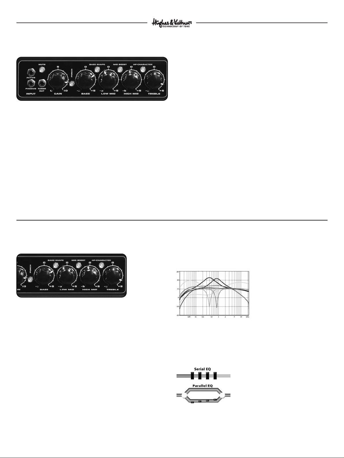
2. Equalizer
2.1 Pure Parallel Technology
Pure Parallel EQ is a technology based on the kind of circuitry
generally found in high-end studio gear. The signal is distributed
to all EQ bands simultaneously rather than being routed through
the bands consecutively. The original signal is routed through via
a passive circuit, practically circling the complete circuit. The filters
for the respective bands arrayed in parallel to this circuit only
process the targeted frequencies, which are then added back to
the original signal.
The Tchebycheff characteristics of the bass and treble filters make
an extremely effectively processed signal possible: neighbouring
frequencies in a selected field are processed in the opposite direction,
i.e. neighbouring frequencies are lowered when a frequency is
boosted, and raised when it is cut. This allows for clearly audible
processing without excessive variations is level.
Another special feature is the automatic adaptation of the Q-factor
of the LOW-MID and HIGH MID bell filters. Frequencies are
boosted in a wider band and cut in a narrower band.
Together, these special features make the EQ an easy-to-use sound
tool that guarantees a superior base tone and makes sound-sculpting
and signal correcting possible with just one control. Extreme musical
results that sound “healthy” in any mode are at your fingertips.
The figure shows the sophisticated parallel EQ circuit in comparison
to a simple serial circuit. Note the bands’ parallel array and the
passive circuit that carries the original signal.
6
Quantum
TM
QT 600 Manual
1. The Preamp
1.1 Tube Touch Circuit™
The preamp section plays a pivotal role in the overall design of the
QT600: As interface between bass player and instrument on the one
hand, and power circuitry on the other, it decisively shapes both the
amp’s response and the instrument’s sonic spectrum. Quantum™
QT600 amps’ inputs feature the Tube Touch Circuit™, resistant to
distortion, which guarantees a direct response to the players’ touch
and prevents dissonant clipping.
1.2 Connections:
Active
Connect bass guitars with active circuitry to this port. (High output
level, low impedance)
Passive
Connect bass guitars with passive circuitry to this port. (Low output
level, high impedance)
1.3 Gain
The GAIN control determines the input level. But it does more than
just adjust the level – in combination with the MASTER control,
it makes a wide range of nuances between clean- and overdrive-
sounds possible.
1.4 Hot
The HOT indicator provides information about the input level.
But it isn’t just a classic control aid – the "magic eye” indicates how
“hot” the preamp is being driven.
1.5 Mute
Mutes the speaker output as well as the DI-Out, LINE-Out and
Headphone -Out. TUNER-Out remains active.
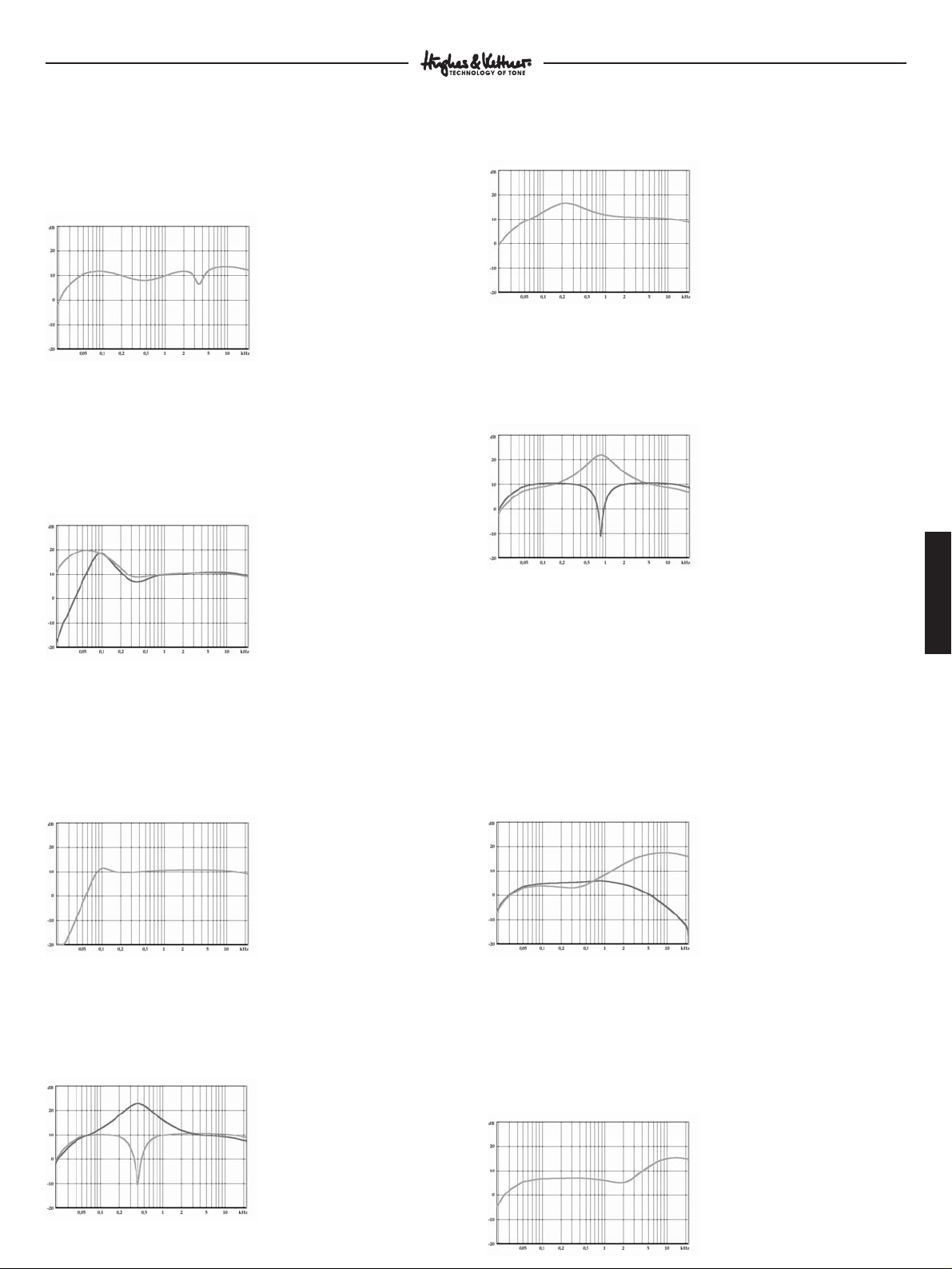
The figure shows the curves of all EQ bands
and switchable filters.
The figure shows a sophisticated parallel EQ circuit in
comparison to a simple serial circuit. Note the bands’
parallel array and the passive circuit that carries the
original signal.
7
ENGLISH
Quantum
TM
QT 600 Manual
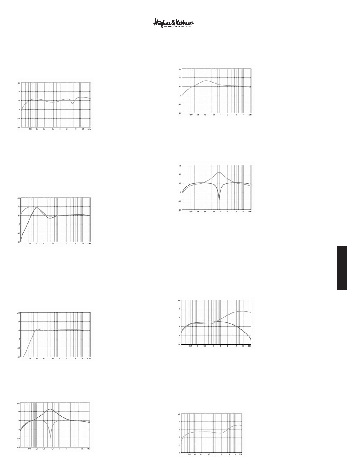
2.2 Punch
Pushing the PUNCH button activates a filter in front of the EQ
whose curve is shaped like that of a tube amp set up to deliver
clean sounds – the result is punchier and more lively sound.
The PUNCH filter’s frequency response is tweaked to ensure
that there is no audible change in overall level.
2.3 Bass
Turning this knob up boosts frequencies ranging from 40 to 200 Hz
(with a centre frequency of 60 Hz), while scooping mids from 300
to 600 Hz. This emphasizes low-end frequencies. Turning the knob
down suppresses the low-end, raises the lower of the two limiting
frequency and boosts frequencies at 100 Hz. The overall energy of
the bass is maintained even when cutting frequencies.
2.4 Bass Shape
Turning on the BASS SHAPE knob activates a low cut filter at 80 Hz
with an edge steepness of 12dB in the bass band. Energy-consuming
sub-bass signals are filtered out, giving the amp and speaker more
room to breathe. Boosting to between 80 Hz and 160 Hz shifts a
portion of the energy one octave higher, which has a particularly
positive effect in problematic stage situations involving bass drums.
2.5 Low Mid
Turning this knob up boosts a broad range of frequencies neighbou-
ring the centre frequency of 400 Hz, adding presence and punch to
the bass signal. Turning this knob down filters out a narrow range
of frequencies around 400 Hz.
2.6 Mid Boost
Activating the MID BOOST knob boosts a broad range of frequencies
around 220 Hz. This pre-filtering is excellent for classic soul sounds.
2.7 High Mid
As with LOW MID, frequencies are boosted in a broad band and
cut in a narrow band. The centre frequency is 800 Hz. This frequency
range is responsible for the “woody“ quality of the signal-boosting
results in a pleasant, woody tone.
2.8 Treble
The TREBLE control has two functions. When the HF CHARACATER
button is deactivated, it works just like a classic level control,
producing a rather “metallic“ sound. The character of the frequency
processing is emphasized by dampening frequencies lying above
the TREBLE control range’s centre frequency.
When the HF CHARACTER button is activated, it works just like
a tube power amp’s presence control, producing delicate, soft top-
end frequencies while simultaneously rolling off “harsher” sounding
frequencies found at the low end of the high frequency range.
Pushing the PUNCH button audibly enhances the effect of the
TREBLE control.
2.9 HF Character
Pushing the HF CHARACTER button activates a filter over the EQ
whose curve is similar to that of a “soft” tweeter. The effect is parti-
cularly prominent in the high-end response of basses with active
circuitry. With passive basses (or instruments whose strings are old)
this effect may barely be audible because there are few high-range
frequencies in the instrument’s signal.
The figure shows the curve of the pre-filter
with the PUNCH button activated
The figure shows the filtering curve with
MID-BOOST activated
The figure shows the HIGH MID EQ’s
curve when boosting (top curve) and
cutting (bottom curve) frequencies
The figure shows the BASS EQ’s curve
when boosting (upper curve) and cutting
(lower curve) frequencies
The figure shows the filtering curve with
BASS SHAPE activated
The figure shows the TREBLE-EQ’s curve
when boosting (top curve) and cutting
(bottom curve) frequencies
The figure shows the pre-filter curve with
HF CHARACTER activated
The figure shows the LOW MID EQ’s
curve when boosting (top curve) and
cutting (bottom curve) frequencies
4. Power Amp
4.1 Dynavalve™ Technology
Dynavalve™ is a new, patented technology. Just like in classic
tube circuitry, the phase-splitter tubes and speaker feedback work
together to “force” the power transistors to act just like amp tubes.
The dynamics, overtone spectrum, and even the impedance
matching to the speakers works exactly like in a tube amp.
The result: better tone, more sound pressure, greater punch!
Note:
All special Quantum™ PRO speakers have integrated HF systems.
The dual cone (10“) or DuraDome™ (15“) design yields a homoge-
nous, wide overtone spectrum without the bundling and phasing
errors that typically arise with HF-horns.
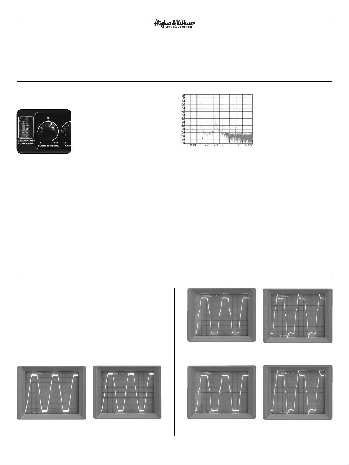
3. Tube Growl
3.1 Tube saturation & compression
Tube Growl is a complex circuit that controls peaks like a tube
preamp does, converting the energy of spikes into overtones rather
than allowing it to dissipate. Not only the fundamental frequency
sounds as though it were generated by a string, but so do the
harmonic overtones, i.e. the frequency generated by the half string,
third, quarter, and so forth.
The relative levels of harmonic overtones are decisive in shaping
tone, so it takes the right mix to yield a warm, punchy sound.
An intelligent compressor controls the tube saturation and prevents
excessive distortion. String attack stays up front – there is no masking
of attack, no pumping sounds, no sonic side effect. Rather, there is
a singing sustain and a punchy sound that’s fun to play.
3.2 Tube Growl
The TUBE GROWL knob, which allows you to dial in natural
compression and tube effects, is a particularly handy feature. It puts
the ability to control the compressor parameters – threshold, ratio,
make-up gain, attach and release – as well as tube saturation levels
at your fingertips.
3.3 Fat
The FAT indicator provides information about the level of tube
saturation. The brighter the “magic eye,” the more powerful the
TUBE GROWL effect.
Quantum
TM
QT 600 Manual
Solid state power amp without
speakers connected
Solid state power amp with
speaker connected
Tube power amp without
speakers connected
Tube power amp with
speaker connected
DynaValve™ power amp without
speakers connected
DynaValve™ power amp with
speaker connected
The figure shows the harmonic overtone
spectrum generated for a fundamental tone
of 500 Hz.
8
4.2 Master
The MASTER knob determines the overall level of the amp.
But it’s more than merely a volume knob – in combination with the
GAIN control, it makes a wide range of nuances between clean and
overdrive-sounds possible.
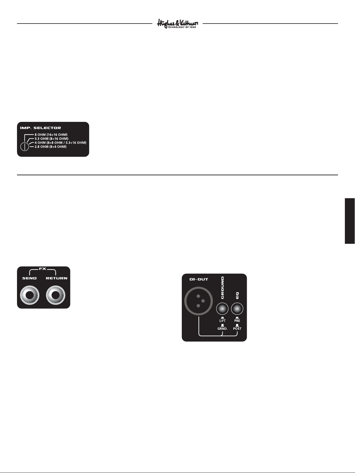
4.2 Impedance Selector
On the reverse of the QT600 there is a selector switch for matching
the QT600 to the impedance (load, resistance, “ohm number”) of
the connected speakers. The following combinations and settings
are possible:
To achieve full sound quality, correct impedance matching absolutely
must be assured, as mismatching prevents the optimal functioning
of the Dynavalve™ concept. An incorrectly matched impedance
leads to incorrect feedback between the amp and speaker, which
results in unsatisfactory tone or inadequate volume.
Note:
Speaker cabinets are generally in parallel. To calculate the total
resistance of two parallel speakers (R1, R2), multiply the individual
resistances, and divide the resulting product by the sum of the
individual resistances. The following formula applies:
R = ( R1 x R2 ) / ( R1 + R2 )
For example, for an 8 ohm and a 16 ohm speaker:
R = ( 8 x 16 ) / ( 8 + 16 )
R = 128 / 24
R = 5.33
ENGLISH
Quantum
TM
QT 600 Manual
Impedance Selector
5. Additional connections
and controls
5.1 Fx Loop
The effects loop is a serial circuit, located after the TUBE GROWL
knob and before LINE OUT in the signal path. Because the signal
from the effects device is patched through serially, the effects balance
must be adjusted on the effects device itself. The effects loop is
footswitchable (Hughes & Kettner
®
FS 2).
Send
Connect this output to the input of the effects device.
Return
Connect the output of the effects device to this input.
5.2 Line Out
This unbalanced line output patches out the preamp signal inclu-
ding effects. Located before the Dynavalve™ amp in the circuitry,
it is independent of the MASTER control setting.
Note:
This output does not patch out the sound of the Dynavalve™
amp and is thus ideal for routing the signal to another amp.
5.3 Di Out
Use this balanced output to connect the QT600 to a mixer or stage
speaker. There are two modes to satisfy the needs of professional
on-stage use:
Pre-EQ
Set to PRE, the DI-OUT reads off the signal directly after the preamp,
making it possible to adjust stage sound and volume independent
of the mixer/PA.
Post-EQ
Set to POST, the DI-OUT reads the signal off “at the speaker,“
patching the full amp signal including effects and EQ through to
the mixer. The signal is thus dependent of the MASTER control
setting, and is shaped by the reciprocal action of speakers and
amp so decisive in determining the Dynavalve sound.
Ground switch
Activating the GROUND switch isolates the ground of the DI-OUT
signal from the ground lift, making it possible to suppress hum
should it occur.
5.4 Tuner
Connect a tuner to this output, which is always active. The MUTE
button can by pushed for muted tuning.
5.5 Headphones
Connect headphones to this jack. The QT600 speaker output is
deactivated when a plug is inserted into this jack.
Fx Loop
DI Out
9
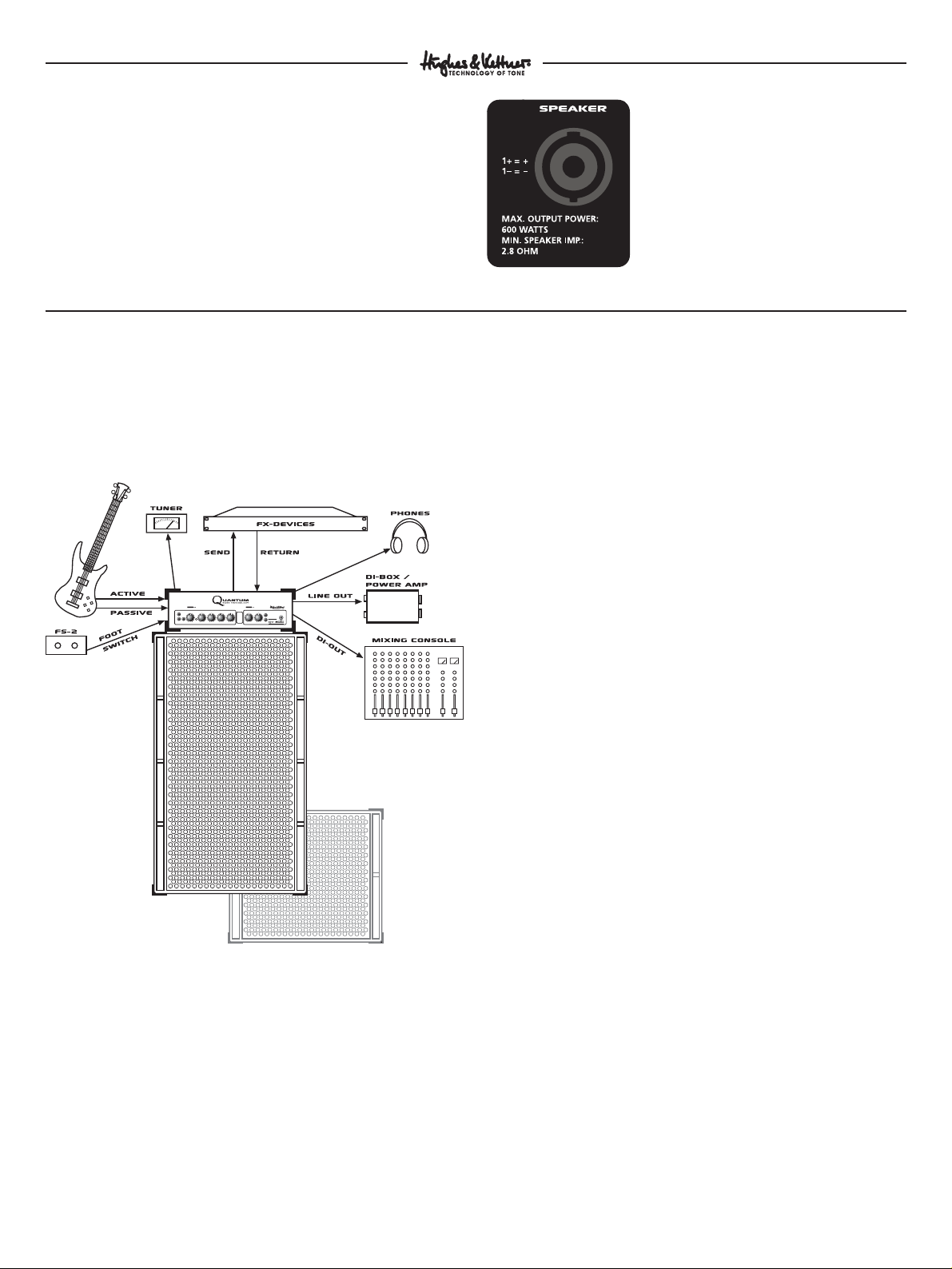
6. Standard setup /
Cable connections
7. Troubleshooting
The amp won’t power up when switched on.
• Check the mains cable to see if it is connected properly.
• Check the mains fuse. If it is defective, replace it with another
fuse with identical ratings. If the defect recurs, consult your local
authorised Quantum™ dealer.
The amp is correctly cabled, but no sound is audible.
• Check to see if the MUTE control is activated.
• Check the setting of the GAIN and MASTER controls.
• Check the effects circuit. An inactive or incorrectly cabled effects
device can interrupt the signal.
• Check the headphones output. If headphones are plugged in,
the speaker output is muted.
The DI OUT causes humming noises when in use.
• The earthing of the connected equipment is causing a ground
loop. Never sever the equipment’s safety ground! Instead, set
the GROUND switch to LIFT. If this fails to resolve the problem,
try plugging both devices into the same power distributor.
• An electrical or magnetic field is generating interference.
Use a better quality cord or try to skilfully reposition the cables
to minimise interference.
Feedback arises when DI OUT is in use.
• If the PA’s sound pressure is extreme enough, it can excite the
amp’s speaker and cause feedback when DI OUT is in use.
Since the speaker’s response influences the amp, it could be
routing the interference signal to the DI OUT. Solution:
Try repositioning the amp or using the LINE OUT instead.
When connecting a mixing console to the DI OUT jack the signal
sounds totally distorted over the PA.
• The mixing console’s input is not set to line level. Adjust the level
accordingly at the mixing console. If this is not possible, either
patch the signal to an unbalanced (line) input at the mixing
console or use a connecting cable equipped with an integrated
balanced voltage divider (available from quality music stores
or PA service companies).
The amp’s output level is too low.
• A device connected to the effects loop is reducing the signal level.
Adjust the signal level using the effects device’s input/output
control.
The amp doesn’t sound the way it usually does.
• Check the impedance matching. Mismatching has a negative
effect on the tone quality of the Dynavalve amp.
10
Quantum
TM
QT 600 Manual
5.6 Footswitch
Connect the optional two-way footswitch (Hughes & Kettner
®
FS-2)
to this jack for switching the FX LOOP and PUNCH.
5.7 Speaker Out
Connect speakers to the Speakon jack. Please make sure to wire
the cable correctly (1+=+, 1-=-) and to match the impedance of the
QT600 to the connected speaker
(Chapter 4.2 IMPEDANCE SELECTOR).
Speaker Out
treble
High Mid
Low midbassgain
tuner
out
input
PUNCH
5
010
5
010
5
010
active
passive
TUBE GROWL
master
headphone
on
off
0
-5 +5
0
-5 +5
0
-5 +5
0
-5 +5
mute bass shape mid boost hf-character
600-WATT-BASS amplifier
fOOTswitch
FX-loop/PUNCH
DYNAVALVE
POWERAMP
TECHNOLOGY

11
ENGLISH
Quantum
TM
QT 600 Manual
8. Service and
maintenance
Quantum™ amps do not require service of any kind. There are
however a few basic rules that, when followed, are sure to extend
the service life of your amp considerably:
• Make sure that all peripheral devices and cables are in a state
of good repair!
• Make sure that air circulates freely around your amp’s ventilation
ducts at all times.
• Absolutely avoid exposure to mechanical shocks, extreme heat,
dust and moisture.
• Pay particular attention to the specifications of peripheral
devices. Never connect devices with high output signal levels
(e.g. amps) to your amp’s input.
• Prior to plugging in your amp, always check that the AC power
source delivers the current the amp is designed to handle.
When in doubt about the local rating, ask the venue’s sound
technician or a stage hand.
• Refrain from ”do it yourself” repairs! Even the replacement of
internal fuses should be entrusted to an experienced technician.
• Use a soft dry cloth to clean the enclosure’s outer surfaces
and metal and acrylic glass surfaces. Never use alcohol or
other solvents!
• Ensure a correct impedance matching. Never fall below an
impedance of 2.7 ohm!
9. Technical
specifications
9.1 Security specifications
Mains input voltage:
220 – 230V
117V
100V
Primary fuse
externally accessible
220 – 230V / T3,15A
117V / T6,3A
100V / T6,3A
Power consumption
Max. power consumption [Watt]: 950W
Inrush current
230V, 90°: A
117V, 90°: A
100V, 90°: A
Temperature indications
Surrounding temperature when in use [°C]: 0° - 70°C
Temperature during storage/transport [°C]: -20° - +85°C
9.2 Mechanical specifications
Dimensions
Absolute dimensions incl. all projecting parts WxHxD:
550mm x 195mm x 320mm
Weight
14.5kg
9.3 Electronic/acoustic specifications
Secondary fuses
Anode voltage: 1x 50mAT
Electronics supply: 2x 630mAT
Output stage: 2x 8AT each IEC 5x20mm, 250V type
Inputs
Active: 6.3mm mono jack
Passive: 6.3mm mono jack
FX Return: 6.3mm mono jack
Footswitch connection : 6.3mm stereo jack
Outputs
Tuner Out: 6.3mm mono jack
Headphone out: 6.3mm stereo jack
FX Send: 6.3mm mono jack
Line Out: 6.3mm mono jack
DI Out: XLR male, balanced
Speaker Out: Speakon
Frequency response
Input to Line Out: 35Hz – 20kHz (+0/-3dB)

12
Quantum
TM
QT 600 Manual
Appendix: Quantum PRO
Speaker Cabinets
A new generation of bass cabinets that combines first-rate audio
features with drastically reduced weight. The heart of the new
Quantum™ PRO cabinets are the Neodym speakers, developed
in cooperation with Eminence
®
. This technology assures a faster,
more precise impulse response and thus a more direct and
controlled response to the player’s touch. In addition, all speakers
have integrated HF systems. The dual cone (in 10“ speakers) or
DuraDome™ design yields a homogenous, wide overtone spectrum
without the bundling and phasing errors that typically arise with
horns.
With their tough laminated wood, solid steel grilles, Speakon
connections and uncompromising processing Quantum™ PRO
cabinets are made for a long, problem-free life in rugged everyday
use on-the-road.
Description Assembly Power Handling Impedance Weight Width Height Depth
Watt Ohm kg cm cm cm
QS 210 PRO 2x10 450 4/16 20.9 67 41.5 40.5
QS 410 PRO 4x10 900 8 32.2 67 60 40.5
QS 610 PRO 6x10 1350 5. 3 46.7 67 90.5 41.5
QS 810 PRO 8x10 1800 4 61.8 67 118 41.5
QS 115 PRO 1x15 300 8 22.5 67 60 40.5
QS 2115 PRO 2x10+1x15 750 2.8 33.8 67 75.5 40.5

13
DEUTSCH
Quantum
TM
QT 600 Manual
Herzlich Willkommen
zum Quantensprung
für Bassisten!
Die körperlich spürbare Energie eines tieffrequenten Impulses, der
heiße Atem einer Röhrenendstufe, die klangliche Präzision eines
High-end Studiogeräts. Kurz gesagt: Der perfekte Ton und das
perfekte Spielgefühl sind der Maßstab für Quantum™ Bass Amps.
Die einzigartige Kombination klassischer und innovativer
Technologien schafft eine neue Bass-Amplification-Klasse, die dem
anspruchsvollen „Working Bass Player“ Musikalität, Souveränität
und Transportierbarkeit in einem bisher nicht vorstellbaren Maß
zur Verfügung stellt.
Viel Spaß und Erfolg mit Ihrem Quantum™ QT600!
INHALT
1. Preamp . . . . . . . . . . . . . . . . . . . . . . . . . . . . . . . . . . . . . . . . . . . . 14
1.1 Tube Touch Circuit™ 14
1.2 Active und Passive 14
1.3 Gain 14
1.4 Hot 14
1.5 Mute 14
2. Equalizer . . . . . . . . . . . . . . . . . . . . . . . . . . . . . . . . . . . . . . . . . . . 14
2.1 Die PureParallel™ Technologie 14
2.2 Punch 15
2.3 Bass 15
2.4 Bass Shape 15
2.5 Low Mid 15
2.6 Mid Boost 15
2.7 High Mid 15
2.8 Treble 15
2.9 HF Character 15
3. Tube Growl . . . . . . . . . . . . . . . . . . . . . . . . . . . . . . . . . . . . . . . . . 16
3.1 Röhrensättigung und Kompression 16
3.2 Tube Growl 16
3.3 Fat 16
4. Poweramp . . . . . . . . . . . . . . . . . . . . . . . . . . . . . . . . . . . . . . . . . . 16
4.1 Die Dynavalve™ Technologie 16
4.2 Master 17
4.3 Impedance Slelector 17
5. Weitere Anschlüsse und Bedienelemente . . . . . . . . . . . . . . . . 17
5.1 Fx Loop 17
5.2 Line Out 17
5.3 Di Out 17
5.4 Tuner 17
5.5 Headphones 17
5.6 Footswitch 18
5.7 Speaker Out 18
6. Standard Setup/Verkabelung . . . . . . . . . . . . . . . . . . . . . . . . . 18
7. Wartung und Pflege . . . . . . . . . . . . . . . . . . . . . . . . . . . . . . . . . . 18
8. Trouble Shooting . . . . . . . . . . . . . . . . . . . . . . . . . . . . . . . . . . . . 19
9. Technische Daten . . . . . . . . . . . . . . . . . . . . . . . . . . . . . . . . . . . . 19
Anhang: Quantum™ PRO Speaker-Cabinets . . . . . . . . . . . . . . . 20
2. Equalizer
2.1 Die PureParallel Technologie
Der PureParallel-EQ basiert auf einem Schaltungskonzept nach
dem Vorbild von High-End Studioequipment. Hierbei wird das
Signal gleichzeitig auf alle EQ-Bänder verteilt, anstatt die Bänder
nacheinander zu durchlaufen. Das Original-Signal wird passiv mit-
geführt, es umgeht praktisch die komplette Elektronik. Die parallel
dazu angeordneten Bänder filtern nur die zu bearbeitenden
Frequenzen und werden dem Originalsignal wieder zugemischt.
Dank der Tchebycheff –Charakteristik des Bass- und Treble-Filters
erreicht man ein äußerst effektiv bearbeitetes Signal: benachbarte
Frequenzen eines ausgewählten Bereiches werden in Gegenrichtung
bearbeitet, d.h. bei Anhebungen werden die benachbarten Fre-
quenzen abgesenkt, bei Absenkungen angehoben. Dadurch wird
eine deutlich hörbare Bearbeitung ohne zu große Pegelunterschiede
möglich.
Eine weitere Besonderheit ist die automatische Anpassung des
Q-Faktors der beiden Glockenfilter LOW-MID und HIGH MID.
Die Filterung verhält sich bei Anhebung breitbandig und bei
Absenkung schmalbandig.
Zusammengenommen machen diese Besonderheiten den EQ zu
einem intuitiv zu bedienenden, bassgerechten Sound-Werkzeug,
mit dem Soundgestaltungen und Signalkorrekturen mit nur einem
Regler möglich werden. Quasi „im Handumdrehen“ erhält man
extrem musikalische Ergebnisse, die in jeder Einstellung „gesund“
klingen.
14
Quantum
TM
QT 600 Manual
1. Der Preamp
1.1 Tube-Touch-Circuit™
Bei der Gesamtkonzeption des QT600 spielt der Preamp eine zentrale
Rolle: Als Interface zwischen dem Bassisten und seinem Instrument
auf der einen und der Leistungselektronik auf der anderen Seite,
entscheidet er maßgeblich über das Spielgefühl und die klangliche
Bandbreite. Die Eingänge des Quantum™ ™-QT600 basieren auf
dem Tube-Touch-Circuit™, einer übersteuerungsfesten Schaltung,
die ein direktes Spielgefühl garantiert. Ein unharmonisches
Clipping ist dabei ausgeschlossen.
1.2 Anschlüsse:
Active
Buchse zum Anschluss von Bässen mit aktiver Elektronik. (Hoher
Ausgangspegel, niedrige Impedanz)
Passive
Buchse zum Anschluss von Bässen mit passiver Elektronik.
(Niedriger Ausgangspegel, hohe Impedanz)
1.3 Gain
Der GAIN-Regler bestimmt den Eingangspegel. Er ist aber nicht
nur ein Pegel-Regler, sondern erlaubt im Zusammenspiel mit dem
MASTER-Regler breit gefächerte Nuancen zwischen cleanen und
angezerrten Sounds.
1.4 Hot
Die HOT-Anzeige informiert über die Höhe des Eingangspegels.
Es handelt sich hierbei aber nicht um eine klassische Aussteuerungs-
hilfe. Das „Magische Auge“ zeigt vielmehr an, wie „heiß“ der
Preamp gefahren wird.
1.5 Mote
MUTE schaltet den Boxenausgang sowie DI-Out, LINE-Out und
den Kopfhörer-Out stumm. TUNER-Out bleibt aktiv.
Die Abbildung zeigt die Kurven aller
EQ-Bänder und der schaltbaren Filter
Die Abbildung zeigt den aufwendigen Signalverlauf
eines parallelen EQs im Vergleich zum einfachen
Verlauf einer seriellen Schaltung. Deutlich zu
erkennen ist die parallele Anordnung der Bänder
sowie die passive Führung des Original-Signals
15
DEUTSCH
Quantum
TM
QT 600 Manual
2.2 Punch
Mit der Aktivierung des PUNCH-Schalters wird ein Filter vor den
EQ geschaltet, dessen Kurve ähnlich verläuft wie bei einem für
Clean Sounds eingestellten Röhrenamp: der Klang wird druckvoller
und spritziger. Der Frequenzgang des PUNCH-Filters ist so abge-
stimmt, dass keine Veränderung des Gesamtpegels spürbar wird.
2.3 Bass
Eine Anhebung betont den Frequenzbereich zwischen 40 und 200 Hz
bei einer Centerfrequenz von 60 Hz. Gleichzeitig bewirkt dies eine
leichte Absenkung der Mitten im Bereich zwischen 300 und 600 Hz.
Dadurch wird der Tiefbassanteil in Szene gesetzt . Eine Absenkung
unterdrückt den Tiefbass, verschiebt die untere Grenzfrequenz nach
oben, und hebt Frequenzen bei 100 Hz an. Die Gesamt-Energie des
Bass-Bereiches bleibt auch bei Absenkungen erhalten.
2.4 Bass Shape
Durch Aktivierung des BASS SHAPE-Schalters wird ein Low Cut-
Filter bei 80 Hz mit einer Flankensteilheit von 12dB in das Bass-
band geschaltet. Energie-fressende Subbass-Signale werden ausge-
filtert, Amp und Box erhalten mehr Luft zum Atmen. Eine Anhebung
zwischen 80Hz und 160 Hz verlagert einen Teil Energie in die darüber
liegende Oktave. Dies wirkt sich besonders bei problematischen
Bühnensituationen im Zusammenspiel mit der Bassdrum positiv aus.
2.5 Low Mid
Eine Anhebung erfolgt breitbandig um die Centerfrequenz 400 Hz.
Dadurch wird der Bass sehr präsent und druckvoll. Absenkungen
filtern Frequenzen um 400 Hz schmalbandig aus.
2.6 Mid Boost
Bei Aktivierung des MID BOOST-Schalters werden Frequenzen um
220 Hz breitbandig angehoben. Diese Vorfilterung ist hervorragend
für klassische Soul-Sounds geeignet.
2.7 High Mid
Wie bei LOW MID erfolgt eine Anhebung breitbandig, eine
Absenkung schmalbandig. Die Centerfrequenz beträgt 800 Hz .
Dieser Frequenzbereich bestimmt den „Holzanteil“ des Signals, bei
Anhebungen erreicht man eine angenehme, holzige Präsenz.
2.8 Treble
Der TREBLE-Regler hat zwei Funktionen. Bei deaktiviertem HF-
CHARACATER-Schalter regelt er wie ein klassischer Höhen-Regler,
und produziert einen eher "drahtigen" Klang. Dabei wird der
Charakter der Frequenzbearbeitung verstärkt, indem die darüber
liegenden Frequenzen abgesenkt werden. Bei gedrücktem HF-
CHARACTER-Schalter arbeitet er wie ein Presence-Regler einer
Röhrenendstufe, und produziert sehr feine, weiche Höhen. Dabei
unterdrückt er gleichzeitig "hart" klingende Höhen aus dem darunter
liegenden Frequenzbereich. Bei Benutzung des PUNCH-Schalters
wird die Wirkung des TREBLE-Reglers deutlich erhöht.
2.9 HF Character
Mit der Aktivierung des HF CHARACTER-Schalters wird ein Filter
vor den EQ geschaltet, dessen Kurve ähnlich verläuft wie die eines
"soften" Hochton-Tweeters. Besonders gut wirkt sich das Filter auf
die Höhenwiedergabe von aktiven Bässen aus. Bei passiven Bässen
(oder Instrumenten mit alten Saiten) kann die Wirkung als gering
empfunden werden, da in diesem Fall weniger hochfrequente
Signale vom Instrument geliefert werden.
Die Abbildung zeigt die Kurve
der Vorfilterung bei aktiviertem
PUNCH-Schalter
Die Abbildung zeigt die Kurve der
Filterung bei aktiviertem MID-BOOST
Die Abbildung zeigt die Kurven bei
Anhebung (obere Kurve) und Absenkung
(untere Kurve) des HIGH MID-EQs
Die Abbildung zeigt die Kurven bei
Anhebung (obere Kurve) und Absenkung
(untere Kurve) des BASS-EQs
Die Abbildung zeigt die Kurve der
Filterung bei aktiviertem BASS SHAPE
Die Abbildung zeigt die Kurven bei
Anhebung (obere Kurve) und Absenkung
(untere Kurve) des TREBLE-EQs
Die Abbildung zeigt die Kurve der Vorfilterung
bei aktiviertem HF CHARACTER-Schalter
Die Abbildung zeigt die Kurven bei
Anhebung (obere Kurve) und Absenkung
(untere Kurve) des LOW MID-EQs
 Loading...