


QSC Audio PL-1.5X, PL-1.0, PL-2.4MB, PL-1.4, PL-2.0HV User Manual
...User Manual
Manuel de l’utilisateur
Bedienhandbuch
Manual del Usuario
▼PL-1.0
▼PL-1.0HV
▼PL-1.4
▼PL-1.5X
▼PL-1.6HVX
▼PL-1.8
▼PL-2.0HV
▼PL-2.4MB
TD-000063-00 |
P o w e r L i g h t |
™ |
S e r i e s |
Rev. C |
|
||
TD-000063-00 |
|
|
|
33

T A B L E O F C O N T E N T S ▼ TA B L E D E S M AT I È R E S ▼ I N H A LT S V E R Z E I C H N I S ▼ TA B L A D E L A S M AT E R I A S
Explanation of graphical symbols ................... |
2 |
Explication des symboles graphiques |
|
Erklärung der Bildsymbole |
|
Explicación de símbolos |
|
FCC Interference Statement .............................. |
3 |
INTRODUCTION ................................................... |
5 |
AVANT-PROPOS |
|
EINFÜHRUNG |
|
INTRODUCCIÓN |
|
Front panel ............................................................ |
6 |
Panneau avant |
|
Vorderseite |
|
Panel frontal |
|
Rear panel ............................................................ |
7 |
Panneau arrière |
|
Rückseite |
|
Panel posterior |
|
MOUNTING ........................................................... |
8 |
MONTAGE |
|
BEFESTIGUNG |
|
MONTAJE |
|
Front ....................................................................... |
8 |
Avant |
|
Vorn |
|
Frente |
|
Rear ....................................................................... |
9 |
Arrière |
|
Hinten |
|
Trasera |
|
Operating voltage (AC mains) ........................ |
10 |
Tension d’utilisation (alimentation CA) |
|
Netz-Betriebspannung |
|
Voltaje de funcionamiento (CA) |
|
Inputs ................................................................... |
10 |
Entrées |
|
Eingänge |
|
Entradas |
|
Data Port ............................................................. |
11 |
Port de données |
|
Data Port |
|
Puerto de datos |
|
Outputs ................................................................ |
11 |
Sorties |
|
Ausgänge |
|
Salidas |
|
Speaker cabling ................................................ |
12 |
Câblage du haut-parleur |
|
Lautsprecherkabel |
|
Cableado de bocinas |
|
OPERATION ......................................................... |
13 |
FONCTIONNEMENT |
|
BETRIEB |
|
OPERACIÓN |
|
Gain controls ...................................................... |
13 |
Commandes de gain |
|
Pegelsteller |
|
Controles de ganancia |
|
Remote power supply control ......................... |
13 |
Télécommande du bloc d’alimentation |
|
Ferneinschaltung |
|
Control remoto de alimentación |
|
Clip limiter .......................................................... |
14 |
Limiteur d'écrêtement |
|
Clip-Limiter |
|
Limitador anti-clip |
|
LED indicators .................................................... |
15 |
Indicateurs DEL |
|
LED-Anzeigen |
|
Indicadores LED |
|
Parallel, stereo, and bridged mono ............... |
16 |
Modes parallèle, stéreo, et mono ponté (bridgé)
Stereobetrieb, Eingangsparallelschaltung, |
|
und Mono-Brückenbetrieb |
|
Paralelo, estéreo, y mono puente |
|
Using the PowerLight 1.5X and 1.6HVX ........................ |
20 |
Utilisation des PowerLight 1.5X et 1.6HVX |
|
Benutzung der PowerLight 1.5X und1.6HVX |
|
Uso del PowerLight 1.5X y 1.6HVX |
|
Using the PowerLight 2.4MB .................................................... |
22 |
Utilisation du PowerLight 2.4MB |
|
Benutzung der PowerLight 2.4MB Endstufe |
|
Uso del PowerLight 2.4MB |
|
PROTECTION ...................................................... |
24 |
PROTECTION |
|
SCHUTZSCHALTUNGEN |
|
PROTECCIÓN |
|
Turn-on/turn-off muting .................................... |
24 |
Mise en sourdine lors de la mise sous/hors tension |
|
Stummschaltung bei Anund Ausschalten |
|
Enmudecimiento de encendido/apagado |
|
Short circuit protection .................................... |
24 |
Protection contre les court-circuits |
|
Schutz bei Kurzschluß |
|
Protección contra corto-circuito |
|
Clip limiting ........................................................ |
24 |
Limiteur d'écrêtement |
|
Übersteuerungsbegrenzung |
|
Limitando clips |
|
Thermal protection ........................................... |
25 |
Protection thermique |
|
Thermische Schutzschaltung |
|
Protección térmica |
|
DC fault protection ........................................... |
25 |
Protection contre une anomalie CC |
|
Schutz gegen Gleichspannung |
|
Protección contra corriente continua |
|
Input/output protection ..................................... |
25 |
Protection entrées/sorties |
|
Eingangs-/Ausgangsschutz |
|
Protección entrada/salida |
|
SPECIFICATIONS ............................................... |
26 |
SPÉCIFICATIONS |
|
TECHNISCHE DATEN |
|
ESPECIFICACIONES |
|
WARRANTY INFORMATION ............................ |
30 |
INFORMATIONS DE GARANTIE |
|
GARANTIEBEDINGUNGEN |
|
INFORMACIÓN DE GARANTÍA |
|
ADDRESS & |
|
TELEPHONE INFORMATION ............................. |
31 |
ADRESSE POSTALE ET NUMÉROS |
|
ANSCHRIFT UND TELEFONNUMMERN |
|
DIRECCIÓN Y TELÉFONO |
|
1
Explanation of
graphical symbols
The lightning flash with arrowhead symbol, within an equilateral triangle, is intended to alert the user to the presence of uninsulated “dangerous voltage” within the product’s enclosure that may be of sufficient magnitude to constitute a risk of electric shock to humans.
The exclamation point within an equilateral triangle is intended to alert the users to the presence of important operating and maintenance (servicing) instructions in the literature accompanying the product.
C A U T I O N
RISK OF ELECTRIC SHOCK
DO NOT OPEN
CAUTION: To reduce the risk of electric shock, do not remove the cover. No user-serviceable parts inside. Refer servicing to qualified service personnel.
WARNING: To prevent fire or electric shock, do not expose this equipment to rain or moisture.
Explication des
symboles graphiques
Le symbole éclair avec pointe de flèche à l'intérieur d'un triangle équilatéral est utilisé pour alerter l'utilisateur de la présence à l'intérieur du coffret de "tension nonisolée dangereuse" d'ampleur suffisante pour constituer un risque de choc électrique pour l'être humain.
Le point d'exclamation à l'intérieur d'un triangle équilatéral est employé pour alerter les utilisateur de la présence d'instructions importantes pour le fonctionnement et l'entretien (service) dans les documents accompagnant l'appareil.
A T T E N T I O N !
RISQUE DE CHOC ÉLECTRIQUE NE PAS OUVRIR
ATTENTION: Pour éviter les risques de choc électrique, ne pas enlever le couvercle. Cet appareil ne comporte aucune pièce pouvant être réparée par l'utilisateur. Confier l'entretien à un technicien qualifié.
AVERTISSEMENT: Pour éviter le risque de choc électrique ou d'incendie, n'exposez cet appareil ni à l'humidité excessive ni aux projections d'eau (pluie, ruissellement, etc …)
Erklärung der
Bildsymbole
Das Blitzzeichen innerhalb eines gleichseitigen Dreiecks warnt den Benutzer vor nicht-isolierter, gefährlicher Spannung im Inneren des Gerätes. Diese Spannung ist hoch genug, um Personen durch elektrischen Schlag zu gefährden.
Das Ausrufungszeichen innerhalb eines gleichseitigen Dreiecks weist den Benutzer auf wichtige Bedienungsund Wartungsanweisungen hin, die in den gerätebegleitenden Unterlagen aufgeführt sind.
V O R S I C H T
GEFAHR EINES
ELEKTRISCHEN SCHLAGES.
NICHT ÖFFNEN!
VORSICHT: Um Gefährdung durch elektrischen Schlag zu vermeiden, darf das Gehäuse nicht geöffnet werden. Es befinden sich keine vom Benutzer reparierbaren Teile im Inneren des Gerätes. Überlassen Sie jegliche Reparatur dem qualifizierten Fachmann.
WARNUNG: Um die Gefahr eines Brandes bzw. eine Verletzung durch elektrischen Schlag zu vermeiden, sollten Sie das Gerät niemals Regen oder Feuchtigkeit aussetzen.
Explicación de
símbolos
El rayo inscrito en un tríangulo equilátero alerta al usuario de la presencia de voltaje peligroso no aislado dentro del producto, que pude ser de nivel suficiente como para constitutuir riesgo de descarga eléctrica para las personas.
El signo de exclamación inscrito en un triángulo equilátero alerta a los usuarios de la presencia de instrucciones importantes de funcionamiento y mantenimiento (servicio) en el manual que acompaña al producto.
P R E C A U C I Ó N
RIESGO DE DESCARGA ELÉCTRICA. NO LO ABRA.
PRECAUCIÓN: Para reducir el riesgo de descarga eléctrica, no quite la tapa. No hay en el interior nada para ajustar por el usuario. Refiera sus reparaciones a personal cualificado de servicio.
AVISO: Para impedir fuegos o descargas eléctricas, no exponga este equipo a la lluvia o la humedad.
2

NOTE:
This equipment has been tested and found to comply with the limits for a Class B digital device, pursuant to part 15 of the FCC Rules. These limits are designed to provide reasonable protection against harmful interference in a residential installation. This equipment generates, uses, and can radiate radio frequency energy and, if not installed and used in accordance with the instructions, may cause harmful interference to radio communications. However, there is no guarantee that interference will not occur in a particular installation. If this equipment does cause harmful interference to radio or television reception, which can be determined by turning the equipment off and on, the user is encouraged to try to correct the interference by one or more of the following measures:
•Reorient or relocate the receiving antenna.
•Increase the separation between the equipment and the receiver.
•Connect the equipment into an outlet on a circuit different from that to which the receiver is connected.
•Consult the dealer or an experienced radio/TV technician for help.
3

© Copyright 1998, 2000 QSC Audio Products, Inc.
QSC® is a registered trademark, and PowerLight™ and MultiSignal Processor™ are trademarks, of QSC Audio Products, Inc. “QSC” and the QSC logo are registered with the U.S. Patent and Trademark Office.
"Combo" is a trademark of Neutrik AG.
All other trademarks are the property of their respective owners.
4

I N T R O D U C T I O N
This manual covers these eight PowerLight models. All are 2RU high (3.5 inches, or 8.9 centimeters) and weigh approximately 18 pounds (8.2 kilograms).
PowerLight 1.0 Two-channel model; 500 watts/channel @ 2 ohms.
"High-voltage" two-channel model; 500 watts/ channel @ 4 ohms.
PowerLight 1.4 Two-channel model; 700 watts/channel @ 2 ohms.
PowerLight 1.5X Bi-amp model; LF channel: 1000 watts @ 2 ohms; HF channel: 500 watts @ 2 ohms.
"High voltage" bi-amp model; LF channel: 1100 watts @ 4 ohms; HF channel:
450 watts @ 4 ohms.
PowerLight 1.8 Two-channel model; 900 watts/channel @ 2 ohms.
"High-voltage" two-channel model; 1000 watts/ channel @ 4 ohms.
"Mono block" single-channel model; 2400 watts @ 2 ohms.
A V A N T - P R O P O S
Ce manuel traite des huit modèles PowerLight ci-dessous. Ils occupent chacun 2 espaces normalisés (3.5 pouces, ou 8.9 centimètres) et pèsent approximativement 18 livres (8.2 kilogrammes).
PowerLight 1.0 Modèle deux canaux; 500 watts par canal @ 2 ohms.
PowerLight 1.0HV Modèle deux canaux "haute tension"; 500 watts par canal @ 4 ohms.
PowerLight 1.4 Modèle deux canaux; 700 watts par canal @ 2 ohms.
PowerLight 1.5X Modèle biamplifié; canal LF: 1000 watts @ 2 ohms; canal HF: 500 watts @ 2 ohms.
PowerLight 1.6HVX Modèle biamplifié "haute tension"; canal LF: 1100 watts @ 4 ohms; canal HF: 450 watts @ 4 ohms.
PowerLight 1.8 Modèle deux canaux; 900 watts par canal @ 2 ohms.
PowerLight 2.0HV Modèle deux canaux "haute tension"; 1000 watts par canal @ 4 ohms.
PowerLight 2.4MB Modèle simple canal "mono bloc"; 2400 watts @ 2 ohms.
E I N F Ü H R U N G
Die Anleitung ist für acht PowerLight-Verstärkertypen mit 2 Höheneinheiten (8,9 cm) und einem Gewicht von ca. 8,2 kg.
PowerLight 1.0
Zweikanalverstärker, 500 W/ Kanal bei 2 Ohm
PowerLight 1.0HV „High Voltage“-
Zweikanalverstärker, 500 W/
Kanal an 4 Ohm
PowerLight 1.4
Zweikanalverstärker, 700 W/
Kanal an 2 Ohm
PowerLight 1.5X Bi-Amp-
Verstärker. Tieftonkanal 1000
W/2 Ohm, Hochton 500 W/2
Ohm.
PowerLight 1.6HVX „High Voltage“-
Bi-Amp-Verstärker. Tieftonkanal
1100 W/4 Ohm, Hochton 450
W/4 Ohm.
PowerLight 1.8
Zweikanalverstärker, 900 W/
Kanal an 2 Ohm
PowerLight 2.0HV „High-Voltage“-
Zweikanalverstärker, 1000 W/
Kanal an 4 Ohm.
PowerLight 2.4MB „Mono-Block“-
Einkanalverstärker. 2400 W/2
Ohm
I N T R O D U C C I Ó N
Este manual cubre estos ocho modelos de amplificadores PowerLight. Todos entran en dos unidades de rack (3.5 pulgadas o 8.9 centímetros) y pesan aproximadamente 18 libras (8.2 kilos).
PowerLight 1.0 Modelo de dos canales; 500 vatios por canal @ 2 ohmios.
PowerLight 1.0HV Modelo "alto voltaje" de dos canales; 500 vatios por canal @ 4 ohmios.
PowerLight 1.4 Modelo de dos canales; 700 vatios por canal @ 2 ohmios.
PowerLight 1.5X Modelo biamplificado; canal de bajos 1000 vatios @ 2 ohmios; canal de altos 500 vatios @ 2 ohmios.
PowerLight 1.6HVX Modelo "alto voltaje" biamplificado; canal de bajo 1000 vatios @ 4 ohmios; canal de altos 450 vatios @ 4 ohmios.
PowerLight 1.8 Modelo de dos canales, 900 vatios por canal @ 2 ohmios.
PowerLight 2.0HV Modelo "alto voltaje" de dos canales; 100 vatios por canal @ 4 ohmios.
PowerLight 2.4MB Modelo mono, un solo canal de 2400 vatios @ 2 ohmios.
5
Model PowerLight 2.0HV shown; other models are similar.
Modèle PowerLight 2.0HV montré; autres modèles similaires.
PowerLight 2.0HV abgebildet. Restliche Verstärkertypen ähnlich.
Se muestra el modelo PowerLight 2.0HV. Los otros modelos son similares.
6
|
|
|
|
|
|
|
|
|
|
|
|
|
|
|
|
|
|
|
|
|
|
|
|
|
|
|
|
|
|
|
|
|
|
|
|
|
|
|
|
|
|
|
|
|
|
|
|
|
|
|
|
|
|
|
|
|
|
|
|
|
|
|
|
|
|
|
|
|
|
|
|
|
|
|
|
|
|
|
|
|
|
|
|
|
|
|
|
|
|
|
|
|
|
|
|
|
|
|
|
|
|
|
|
|
|
|
|
|
|
|
|
|
|
|
|
|
|
|
|
|
|
|
|
|
|
|
|
|
|
|
|
|
|
|
|
|
|
|
|
|
|
|
|
|
|
|
|
|
|
|
|
|
|
|
|
|
|
|
|
|
|
|
|
|
|
|
|
|
|
|
|
|
|
|
|
|
|
|
|
|
|
|
|
|
|
|
|
|
|
|
|
|
|
|
|
|
|
|
|
|
|
|
|
|
|
|
|
|
|
|
|
|
|
|
|
|
|
|
|
|
|
|
|
|
|
|
|
|
|
|
|
|
|
|
|
|
|
|
|
|
|
|
|
|
|
|
|
|
|
|
|
|
|
|
|
|
|
|
|
|
|
|
|
|
|
|
|
|
|
|
|
|
|
|
|
|
|
|
|
|
|
|
|
|
|
|
|
|
|
|
|
|
|
|
|
|
|
|
|
|
|
|
|
|
|
|
|
|
|
|
|
|
|
|
|
|
|
|
|
|
|
|
|
|
|
|
|
|
|
|
|
|
|
|
|
|
|
|
|
|
|
|
|
|
|
|
|
|
|
|
|
|
|
|
|
|
|
|
|
|
|
|
|
|
|
|
|
|
|
|
|
|
|
|
|
|
|
|
|
|
|
|
|
|
|
|
|
|
|
|
|
|
|
|
|
|
|
|
|
|
|
|
|
|
|
|
|
|
|
|
|
|
|
|
|
|
|
|
|
|
|
|
|
|
|
|
|
|
|
|
|
|
|
|
|
|
|
|
|
|
|
|
|
|
|
|
|
|
|
|
|
|
|
|
|
|
|
|
|
|
|
|
|
|
|
|
|
|
|
|
|
|
|
|
|
|
|
|
|
|
|
|
|
|
|
|
|
|
|
|
|
|
|
|
|
|
|
|
|
|
|
|
|
|
|
|
|
|
|
|
|
|
|
|
|
|
|
|
|
|
|
|
|
|
|
|
|
|
|
|
|
|
|
|
|
|
|
|
|
|
|
|
|
|
|
|
|
|
|
|
|
|
|
|
|
|
|
|
|
|
|
|
|
|
|
|
|
|
|
|
|
|
|
|
|
|
|
|
|
|
|
|
|
|
|
|
|
|
|
|
|
|
|
|
|
|
|
|
|
|
|
|
|
|
|
|
|
|
|
|
|
|
|
|
|
|
|
|
|
|
|
|
|
|
|
|
|
|
|
|
|
|
|
|
|
|
|
|
|
|
|
|
|
|
|
|
|
|
|
|
|
|
|
|
|
|
|
|
|
|
|
|
|
|
|
|
|
|
|
|
|
|
|
|
|
|
|
|
|
|
|
|
|
|
|
|
|
|
|
|
|
|
|
|
|
|
|
|
|
|
|
|
|
|
|
|
|
|
|
|
|
|
|
|
|
|
|
|
|
|
|
|
|
|
|
|
|
|
|
|
|
|
|
|
|
|
|
|
|
|
|
|
|
|
|
|
|
|
|
|
|
|
|
|
|
|
|
|
|
|
|
|
|
|
|
|
|
|
|
|
|
|
|
|
|
|
|
|
|
|
|
|
|
|
|
|
|
|
|
|
|
|
|
|
|
|
|
|
|
|
|
|
|
|
|
|
|
|
|
|
|
|
|
|
|
|
|
|
|
|
|
|
|
|
|
|
|
|
|
|
|
|
|
|
|
|
|
|
|
|
|
|
|
|
|
|
|
|
|
|
|
|
|
|
|
|
|
|
|
|
|
|
|
|
|
|
|
|
|
|
|
|
|
|
|
|
|
|
|
|
|
|
|
|
|
|
|
|
|
|
|
|
|
|
|
|
|
|
|
|
|
|
|
|
|
|
|
|
|
|
|
|
|
|
|
Front panel |
|
|
Panneau avant |
Vorderseite |
|
Panel frontal |
||||||||||||||||||||||||||||||||||||||||||||||
|
|
|
|
|
|
|
||||||||||||||||||||||||||||||||||||||||||||||||||
|
|
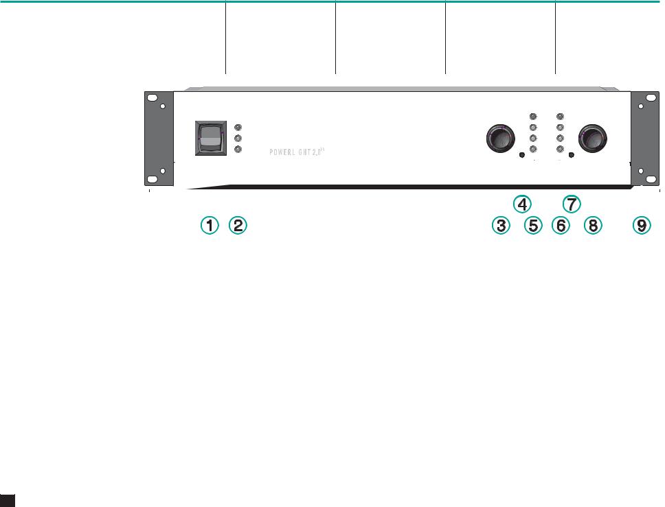
1. |
Power switch |
|
1. |
Commande marche/arrêt |
1. |
Netzschalter |
1. |
Interruptor de encendido |
||||||||||||||||||||||||||||||||||||||||||||||
|
|
2. |
Protect, Standby, and Power |
|
2. |
DELs (Diode ElectroLuminescente) |
2. |
LED-Anzeige für |
2. |
Indicadores LED de Protección, |
||||||||||||||||||||||||||||||||||||||||||||||
|
|
|
|
|
LEDs |
|
|
|
|
|
de modes Protect (protection), |
|
|
|
|
Schutzschaltung, Standby und |
|
|
“Standby” y Operación |
|||||||||||||||||||||||||||||||||||||
|
|
|
|
3. |
Gain control (Channel 1) |
|
|
|
|
|
Standby (en attente), et Power (en |
|
|
|
|
Betrieb |
3. |
Control de ganancia (Canal 1) |
||||||||||||||||||||||||||||||||||||||
|
|
|
|
|
|
|
fonction) |
|
|
|
|
|
|
|
|
|
||||||||||||||||||||||||||||||||||||||||
|
|
|
|
|
|
|
|
|
|
|
|
3. |
Pegelsteller (Kanal 1) |
|
|
|
|
|
|
|
||||||||||||||||||||||||||||||||||||
|
|
|
|
4. |
Clip limiter switch (Channel 1) |
|
|
|
|
|
|
|
|
|
|
|
|
|
|
|
|
|
|
|
|
|
|
|
|
|
|
|
|
|
|
|
|
|
|
4. |
Conmutador de limitador-clip |
|||||||||||||||
|
|
|
3. |
Commande de gain (Canal 1) |
|
|
|
|
|
|
|
|
|
|||||||||||||||||||||||||||||||||||||||||||
|
|
|
|
|
|
|
|
4. |
Schalter für Clip-Limiter (Kanal |
|
|
(Canal 1) |
||||||||||||||||||||||||||||||||||||||||||||
|
|
|
|
5. |
Clip, -10 dB, -20 dB and Signal |
|
|
|
|
|
|
|
|
|
|
|
|
|
|
|
|
|
|
|
|
|
|
|
|
|
|
|
|
|
|
|
|
|
|
|
|
|||||||||||||||
|
|
|
4. |
Sélecteur de limiteur |
|
|
|
|
1) |
|
|
|
|
|
|
|
|
|
|
|||||||||||||||||||||||||||||||||||||
|
|
|
|
|
LEDs (Channel 1) |
|
|
|
|
|
|
|
|
|
5. Indicadores LED de “Clip,” -10 |
|||||||||||||||||||||||||||||||||||||||||
|
|
|
|
|
|
|
|
|
|
d'écrêtement (Canal 1) |
|
|
|
|
|
|
|
|
|
|
||||||||||||||||||||||||||||||||||||
|
|
|
|
|
|
|
|
|
|
|
|
5. |
LED-Anzeige für Clip, -10 dB, -20 |
|
|
dB, -20 dB y “Signal” (Canal 1) |
||||||||||||||||||||||||||||||||||||||||
|
|
|
|
6. |
Clip, -10 dB, -20 dB and Signal |
|
|
|
|
|
|
|
|
|
|
|
|
|
|
|
|
|
|
|
|
|
|
|
|
|
|
|
|
|
|
|
|
|
|
|
|
|||||||||||||||
|
|
|
5. |
DELs de Clip, -10 dB, -20 dB, et |
|
|
|
|
dB und Signal (Kanal 1) |
|
|
|
|
|
|
|
||||||||||||||||||||||||||||||||||||||||
|
|
|
|
|
LEDs (Channel 2) |
|
|
|
|
|
|
6. Indicadores LED de “Clip,” -10 |
||||||||||||||||||||||||||||||||||||||||||||
|
|
|
|
|
|
|
|
|
|
Signal (Canal 1) |
|
|
|
|
|
|
|
|
|
|
||||||||||||||||||||||||||||||||||||
|
|
|
|
|
|
|
|
|
|
|
|
6. |
LED-Anzeige für Clip, -10 dB, -20 |
|
|
dB, -20 dB y “Signal” (Canal 2) |
||||||||||||||||||||||||||||||||||||||||
|
|
|
|
7. |
Clip limiter switch (Channel 2) |
|
|
|
|
|
|
|
|
|
|
|
|
|
|
|
|
|
|
|
|
|
|
|
|
|
|
|
|
|
|
|
|
|
|
|
|
|||||||||||||||
|
|
|
6. |
DELs de Clip, -10 dB, -20 dB, et |
|
|
|
|
dB und Signal (Kanal 2) |
|
|
|
|
|
|
|
||||||||||||||||||||||||||||||||||||||||
|
|
|
|
|
|
|
|
|
|
|
|
|
7. Conmutador de limitador-clip |
|||||||||||||||||||||||||||||||||||||||||||
|
|
|
|
8. |
Gain control (Channel 2) |
|
|
|
|
|
Signal (Canal 2) |
|
|
|
|
|
|
|
|
|
|
|||||||||||||||||||||||||||||||||||
|
|
|
|
|
|
|
7. |
Schalter für Clip-Limiter (Kanal |
|
|
(Canal 2) |
|||||||||||||||||||||||||||||||||||||||||||||
|
|
|
|
|
|
|
|
|
|
|
|
|
|
|
|
|
|
|
|
|
|
|
|
|
|
|
|
|
|
|
|
|
|
|
|
|
|
|
|
|
|
|
||||||||||||||
|
|
9. |
Mounting holes for handles |
|
7. |
Sélecteur de limiteur |
|
|
|
|
2) |
|
|
|
|
8. Control de ganancia (Canal 2) |
||||||||||||||||||||||||||||||||||||||||
|
|
|
|
|
|
|
|
|
|
|
|
d'écrêtement (Canal 2) |
|
|
|
|
|
|
|
|
|
|
||||||||||||||||||||||||||||||||||
|
|
|
|
|
|
|
|
|
|
|
|
8. |
Pegelsteller (Kanal 2) |
|
|
|
|
|
|
|
||||||||||||||||||||||||||||||||||||
|
|
|
|
|
|
|
|
|
|
|
|
|
|
|
|
|
|
|
|
|
|
|
|
|
|
|
|
|
|
|
|
|
|
|
|
|
|
|
|
|
|
9. Agujeros para montaje de asas |
||||||||||||||
|
|
|
|
|
|
|
|
8. |
Commande de gain (Canal 2) |
|
|
|
|
|
|
|
|
|
|
|||||||||||||||||||||||||||||||||||||
|
|
|
|
|
|
|
|
9. |
Griffbefestigungslöcher |
|
|
|
|
|
|
|
||||||||||||||||||||||||||||||||||||||||
|
|
|
|
|
|
|
|
|
|
|
|
|
|
|
|
|
|
|
|
|
|
|
|
|
|
|
|
|
|
|
|
|
|
|
|
|
|
|
|
|
|
|
|
|
|
|
|
|||||||||
|
|
|
|
|
|
|
|
9. |
Trous de montage pour poignées |
|
|
|
|
|
|
|
|
|
|
|
|
|
|
|
|
|||||||||||||||||||||||||||||||
|
|
|
|
|
|
|
|
|
|
|
|
|
|
|
|
|
|
|
|
|
|
|
|
|||||||||||||||||||||||||||||||||

Model PowerLight 2.0HV shown; other models are similar.
Modèle PowerLight 2.0HV montré; autres modèles similaires.
PowerLight 2.0HV abgebildet. Restliche Verstärkertypen ähnlich.
Se muestra el modelo PowerLight 2.0HV. Los otros modelos son similares.
|
|
|
|
|
|
|
|
|
|
|
|
|
|
|
|
|
|
|
|
|
|
|
|
|
|
|
|
|
|
|
|
|
|
|
|
|
|
|
|
|
|
|
|
|
|
|
|
|
|
|
|
|
|
|
|
|
|
|
|
|
|
|
|
|
|
|
|
|
|
|
|
|
|
|
|
|
|
|
|
|
|
|
|
|
|
|
|
|
|
|
|
|
|
|
|
|
|
|
|
|
|
|
|
|
|
|
|
|
|
|
|
|
|
|
|
|
|
|
|
|
|
|
|
|
|
|
|
|
|
|
|
|
|
|
|
|
|
|
|
|
|
|
|
|
|
|
|
|
|
|
|
|
|
|
|
|
|
|
|
|
|
|
|
|
|
|
|
|
|
|
|
|
|
|
|
|
|
|
|
|
|
|
|
|
|
|
|
|
|
|
|
|
|
|
|
|
|
|
|
|
|
|
|
|
|
|
|
|
|
|
|
|
|
|
|
|
|
|
|
|
|
|
|
|
|
|
|
|
|
|
|
|
|
|
|
|
|
|
|
|
|
|
|
|
|
|
|
|
|
|
|
|
|
|
|
|
|
|
|
|
|
|
|
|
|
|
|
|
|
|
|
|
|
|
|
|
|
|
|
|
|
|
|
|
|
|
|
|
|
|
|
|
|
|
|
|
|
|
|
|
|
|
|
|
|
|
|
|
|
|
|
|
|
|
|
|
|
|
|
|
|
|
|
|
|
|
|
|
|
|
|
|
|
|
|
|
|
|
|
|
|
|
|
|
|
|
|
|
|
|
|
|
|
|
|
|
|
|
|
|
|
|
|
|
|
|
|
|
|
|
|
|
|
|
|
|
|
|
|
|
|
|
|
|
|
|
|
|
|
|
|
|
|
|
|
|
|
|
|
|
|
|
|
|
|
|
|
|
|
|
|
|
|
|
|
|
|
|
|
|
|
|
|
|
|
|
|
|
|
|
|
|
|
|
|
|
|
|
|
|
|
|
|
|
|
|
|
|
|
|
|
|
|
|
|
|
|
|
|
|
|
|
|
|
|
|
|
|
|
|
|
|
|
|
|
|
|
|
|
|
|
|
|
|
|
|
|
|
|
|
|
|
|
|
|
|
|
|
|
|
|
|
|
|
|
|
|
|
|
|
|
|
|
|
|
|
|
|
|
|
|
|
|
|
|
|
|
|
|
|
|
|
|
|
|
|
|
|
|
|
|
|
|
|
|
|
|
|
|
|
|
|
|
|
|
|
|
|
|
|
|
|
|
|
|
|
|
|
|
|
|
|
|
|
|
|
|
|
|
|
|
|
|
|
|
|
|
|
|
|
|
|
|
|
|
|
|
|
|
|
|
|
|
|
|
|
|
|
|
|
|
|
|
|
|
|
|
|
|
|
|
|
|
|
|
|
|
|
|
|
|
|
|
|
|
|
|
|
|
|
|
|
|
|
|
|
|
|
|
|
|
|
|
|
|
|
|
|
|
|
|
|
|
|
|
|
|
|
|
|
|
|
|
|
|
|
|
|
|
|
|
|
|
|
|
|
|
|
|
|
|
|
|
|
|
|
|
|
|
|
|
|
|
|
|
|
|
|
|
|
|
|
|
|
|
|
|
|
|
|
|
|
|
|
|
|
|
|
|
|
|
|
|
|
|
|
|
|
|
|
|
|
|
|
|
|
|
|
|
|
|
|
|
|
|
|
|
|
|
|
|
|
|
|
|
|
|
|
|
|
|
|
|
|
|
|
Rear panel |
Panneau arrière |
|
Rückseite |
|
Panel posterior |
|||||||||||||||||
|
|
|
|
|
|
|
|
|
|
|
|||||||||||||||||||||
|
|
1. |
Parallel/Stereo/Bridge switch |
1. |
Sélecteur de mode Parallel/ |
|
1. |
Umschalter für |
|
1. |
Conmutador de Paralelo/ |
||||||||||||||||||||
|
|
|
|
|
|
|
|
2. |
Data port |
|
|
Stereo/Bridge (Parallèle/ |
|
|
Eingangsparallelschaltung, |
|
|
Estéreo/Puente |
|||||||||||||
|
|
|
|
Stéréo/Ponté) |
|
|
Stereobetrieb, Mono- |
|
|
|
|
|
|
|
|
|
|||||||||||||||
|
|
|
|
|
|
|
|
|
|
|
|
|
|
|
|
|
|
2. |
Puerto de datos |
||||||||||||
|
|
|
|
|
|
|
|
3. |
Input barrier strip |
|
|
|
|
|
|
Brückenschaltung |
|
||||||||||||||
|
|
2. |
Port de données |
|
|
|
|
|
|
|
|
|
|
|
|||||||||||||||||
|
|
|
|
|
|
|
|
|
|
|
|
|
|
|
|
|
|
|
|
3. |
Tira de terminales de entrada |
||||||||||
|
|
|
|
|
|
|
|
4. |
Input (Channel 1) |
|
|
|
|
|
2. |
Data Port |
|
||||||||||||||
|
|
3. |
Bornes d’entrée |
|
|
|
|
|
|
|
|
|
|
||||||||||||||||||
|
|
|
|
|
|
|
|
|
|
|
|
|
|
|
|
|
|
|
|
4. |
Entrada (Canal 1) |
||||||||||
|
|
|
|
|
|
|
|
5. |
Input (Channel 2) |
|
|
|
|
|
3. |
Eingangs-Schraubanschlüsse |
|
||||||||||||||
|
|
4. |
Entrée (Canal 1) |
|
|
|
|
|
|
|
|
|
|
||||||||||||||||||
|
|
|
|
|
|
|
|
|
|
|
|
|
|
|
|
|
|
|
|
5. |
Entrada (Canal 2) |
||||||||||
|
|
|
|
|
|
|
|
6. |
+ Output (Channel 1) |
|
|
|
|
|
4. |
Eingang (Kanal 1) |
|
||||||||||||||
|
|
5. |
Entrée (Canal 2) |
|
|
|
|
|
|
|
|
|
|
||||||||||||||||||
|
|
|
|
|
|
|
|
|
|
|
|
|
|
|
|
|
|
|
|
6. |
Salida + (Canal 1) |
||||||||||
|
|
|
|
|
|
|
|
7. |
+ Output (Channel 2) |
|
|
|
|
|
5. |
Eingang (Kanal 2) |
|
||||||||||||||
|
|
6. |
Sortie + (Canal 1) |
|
|
|
|
|
|
|
|
|
|
||||||||||||||||||
|
|
|
|
|
|
|
|
|
|
|
|
|
|
|
|
|
|
|
|
7. |
Salida + (Canal 2) |
||||||||||
|
|
|
|
|
|
|
|
8. |
- Output (Channel 1) |
|
|
|
|
|
6. |
+ Ausgang (Kanal 1) |
|
||||||||||||||
|
|
7. |
Sortie + (Canal 2) |
|
|
|
|
|
|
|
|
|
|
||||||||||||||||||
|
|
|
|
|
|
|
|
|
|
|
|
|
|
|
|
|
|
|
|
8. |
Salida - (Canal 1) |
||||||||||
|
|
|
|
|
|
|
|
9. |
- Output (Channel 2) |
|
|
|
|
|
7. |
+ Ausgang (Kanal 2) |
|
||||||||||||||
|
|
8. |
Sortie - (Canal 1) |
|
|
|
|
|
|
|
|
|
|
||||||||||||||||||
|
|
|
|
|
|
|
|
|
|
|
|
|
|
|
|
|
|
|
|
9. |
Salida - (Canal 2) |
||||||||||
|
|
|
|
|
|
|
|
|
10. Cooling fan |
|
|
|
|
|
8. |
- Ausgang (Kanal 1) |
|
||||||||||||||
|
|
|
|
|
|
|
|
|
9. |
Sortie - (Canal 2) |
|
|
|
|
|
|
|
|
|
|
|||||||||||
|
|
|
|
|
|
|
|
|
|
|
|
|
|
|
|
|
|
|
|
10. |
Ventilador |
||||||||||
|
|
|
|
|
|
|
|
|
11. Remote power supply control |
|
|
|
|
|
9. |
- Ausgang (Kanal 2) |
|
||||||||||||||
|
|
|
|
|
|
|
|
|
10. Ventilateur |
|
|
|
|
|
|
|
|
|
|
||||||||||||
|
|
|
|
|
|
|
|
|
|
|
|
|
|
|
|
|
|
|
|
11. |
Control remoto de alimentación |
||||||||||
|
|
|
|
|
|
|
|
|
12. AC mains cable |
|
|
|
|
|
10. |
Lüfter |
|
||||||||||||||
|
|
|
|
|
|
|
|
|
11. Télécommande du bloc |
|
|
|
|
|
|
|
|
|
|
||||||||||||
|
|
|
|
|
|
|
|
|
|
|
|
|
|
|
|
|
|
|
|
12. |
Cable de red |
||||||||||
|
|
|
|
|
|
|
|
|
13. Rear chassis support tab |
|
|
d’alimentation. |
|
11. |
Ferneinschaltung |
|
|||||||||||||||
|
|
|
|
|
|
|
|
|
|
|
|
|
|
|
|
|
|
|
|
|
|||||||||||
|
|
|
|
|
|
|
|
|
|
|
|
|
12. Câble d’alimentation secteur |
|
12. |
Netzkabel |
|
13. |
Lengüeta de soporte de la |
||||||||||||
|
|
|
|
|
|
|
|
|
|
|
|
|
|
|
|
trasera del chasis |
|||||||||||||||
|
|
|
|
|
|
|
|
|
|
|
|
|
|
|
|
|
|
|
|
|
|
|
|
|
|||||||
|
|
|
|
|
|
|
|
|
|
|
|
|
13. Patte de support de l’arrière du |
|
13. Hintere Rackbefestigung |
|
|
|
|
|
|
|
|
|
|||||||
|
|
|
|
|
|
|
|
|
|
|
|
|
|
|
châssis |
|
|
|
|
|
|
|
|
|
|
|
|
|
|
|
|
7
M O U N T I N G M O N T A G E B E F E S T I G U N G M O N T A J E
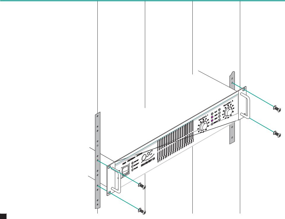
Front |
Avant |
Vorn |
Frente |
Use four mounting screws. |
Utiliser quatre vis de montage. |
Benutzen Sie vier |
Utilice cuatro tornillos. |
|
|
Befestigungsschrauben. |
|
8
Rear
Rear rack ears are optional but recommended. Kits are available from QSC’s Technical Services Department or from your local dealer/distributor.
Arrière
Bien que facultatif, l’installation d’un support à l’arrière de l’amplificateur est recommandé. Un jeu de plaquettes est disponible à cet effet au département des services techniques ou chez votre marchand/ distributeur local.
Hinten
Rückseitige 19"- Befestigungslaschen sind nicht im Lieferumfang, können aber von Ihrem Fachhändler bezogen werden. Diese werden an den vorhandenen Gehäuselaschen befestigt.
Trasera
Las orejas traseras para montaje en rack son opcionales, pero se recomiendan. Existen “kits” disponibles de el departamento de servicios técnicos de QSC o de su distribuidor.
9
 Loading...