


DSP-30
Hardware Manual
DSP-30
2.2 XLR
Rack-mount, 2 Channel Digital Signal Processor
*TD-000097-00*
TD-000097-00
Rev.B
1
WARNING!
WHILE QSC HAS ENDEAVORED TO DEVELOP AND PRODUCE THE MOST DEPENDABLE AND ROBUST DIGITAL SIGNAL
PROCESSOR (DSP) AUDIO PRODUCT FOR YOUR USE, DUE TO THE UNLIMITED AND POTENTIALLY DESTRUCTIVE (TO THE
SOUND SYSTEM) CONFIGURATIONS THAT MAY BE APPLIED TO THE DSP BY THE USER, QSC CANNOT BE HELD RESPONSIBLE
FOR DAMAGES RESULTING FROM ANY DEVIATION OR FAILURE BY THE USER TO STRICTLY FOLLOW THE RECOMMENDA-
TIONS SET FORTH IN THE OWNER’S MANUAL FOR THE INTEGRATION OF THE DSP AND SIGNAL MANAGER SOFTWARE WITH
YOUR SOUND SYSTEM.
ALL RISKS ATTENDANT TO INTEGRATION OF USER-CONFIGURABLE DSP PRODUCTS WITH YOUR SOUND SYSTEM ARE
ASSUMED BY YOU. WHILE QSC STRIVES TO SUPPLY THE HIGHEST QUALITY TECHNICAL SOLUTIONS FOR DIGITAL SIGNAL
PROCESSING, IN NO EVENT WILL QSC OR ITS SUPPLIERS BE HELD LIABLE FOR ANY DAMAGES, CONSEQUENTIAL,
INCIDENTAL, OR OTHERWISE, INCLUDING ANY CLAIMS FOR LOST PROFITS AND/OR SAVINGS RESULTING FROM ANY
ATTEMPTED INTEGRATION OF THE DSP AND SIGNAL MANAGER SOFTWARE WHICH DOES NOT STRICTLY ADHERE TO THE
MANUAL’S RECOMMENDATIONS.
IMPORTANT SAFETY INFORMATION: PLEASE REVIEW!
EXPLANATION OF GRAPHICAL SYMBOLS
Federal Communications
Commission (FCC)
Information
NOTE: This equipment has been tested
and found to comply with the limits for a
Class B digital device, pursuant to Part 15
of the FCC Rules. These limits are de-
signed to provide reasonable protection
against harmful interference in a com-
mercial installation. This equipment gen-
erates, uses, and can radiate radio fre-
quency energy and, if not installed and
used in accordance with the instructions,
may cause harmful interference to radio
communications. Operation of this equip-
ment in a residential area is likely to
cause harmful interference, in which case
the user will be required to correct the
interference at his or her own expense.
The lightning flash with arrowhead symbol, within an equilateral
triangle, is intended to alert the user to the presence of uninsulated “dangerous voltage” within the product’s enclosure that
may be of sufficient magnitude to constitute a risk of electric
shock to humans.
The exclamation point within an equilateral triangle is intended
to alert the users to the presence of important operating and
maintenance (servicing) instructions in the literature accompanying the product.
CAUTION
RISK OF ELECTRIC SHOCK
DO NOT OPEN
CAUTION: To reduce the risk of electric shock, do not remove
the cover. No user-serviceable parts inside. Refer servicing to
qualified service personnel.
WARNING: To prevent fire or electric shock, do not expose this
equipment to rain or moisture.
SAFEGUARDS
Electrical energy can perform many useful functions. This unit
has been engineered and manufactured to assure your personal
safety. Improper use can result in potential electrical shock or fire
hazards. In order not to defeat the safeguards, observe the
following instructions for its installation, use and servicing.
2

Table of Contents
INTRODUCTION Product Overview..................................................................4
Front and Rear Panel Illustrations and Dimensions.................4
INSTALLATION Unpacking..................................................................................................6
What is Included...................................................................................6
Mounting............................................................................................6
Connections:
Balanced Audio Connector Pinouts........................7
Unbalanced Audio Connector Pinouts................................8
Audio Inputs and Outputs..........................................9
RS-232 Port....................................................................10
System Requirements...........................................................................11
Software Installation...........................................................................11
USE Control, Indicator, and Connector Descriptions..................12
General Use Guidelines.................................................................14
Presets....................................................................................15
How to save presets into the DSP-30...........................................15
How to recall Presets ...............................................................16
Lockout feature use.......................................................................17
Contact closure Feature .............................................................18
RS-232 pinout.........................................................................19
Application Example....................................................................20
SPECIFICATIONS.......................................................................................................................................................22
ARCHITECT’S & ENGINEER’S SPECIFICATION..............................................................................................24
QSC INFORMATION Maintenance, Warranty & QSC Contact Information................................25
© Copyright 2001, QSC Audio Products, Inc.
QSC® is a registered trademark of QSC Audio Products, Inc., Costa Mesa, CA
“QSC” and the QSC logo are registered with the U.S. Patent and Trademark Office
3
Introduction: Overview and Illustrations
Overview
The DSP-30 and Signal Manager software combine easy-touse, customizable, two-channel DSP with simple operatingmode selection that requires only two buttons to operate. It
can be used with all amplifiers and is housed in a 1-RU , 19-inch
rack-mount steel chassis. Sampling frequency is 48 kHz. with
24-bit resolution. Dynamic range is greater than 93dB. It is
absolutely rugged and dependable in the spirit of all QSC
professional audio products and fully suited for the rigors of
touring use.
Processing capabilities of the DSP-30 include compressors,
limiters, delays, parametric EQ, high/low pass filters, high/low
shelf filters, test signal generators (sine-wave, pink- and
white-noise), splitters/mixers, polarity reversal, gain/attenuation, and metering. A feature called “Predictive Delay” enables the DSP-30’s compressors and limiters to produce less
signal distortion than their analog counterparts, especially for
fast attack times. Predictive delay adds time delay to the signal
path and must be accounted for to maintain proper time
allignment. Using the Signal Manager software, predictive
delay may be turned on or off; when on, it will provide time
delay information to the operator.
The DSP-30 provides powerful signal processing while keeping operation as simple. Preset operating modes are userselectable by scrolling through the list of numbered Presets on
the front panel display and selecting. The DSP-30 will mute,
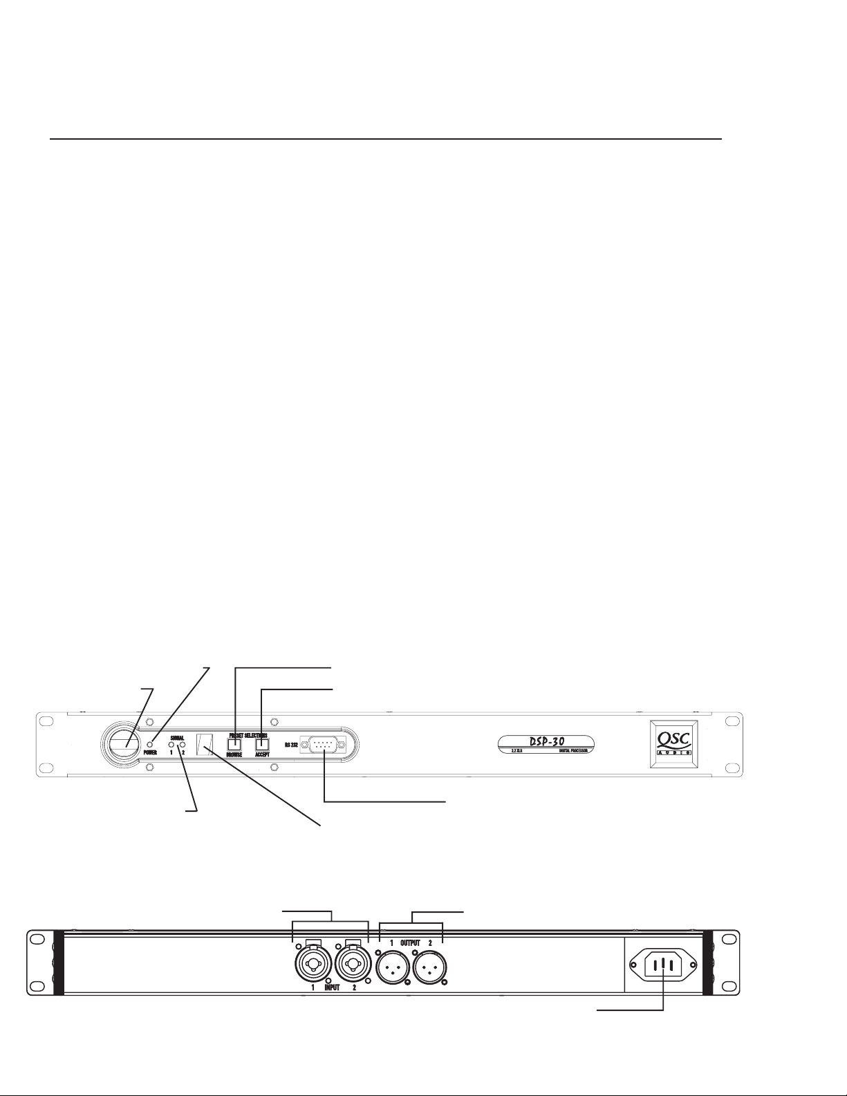
Front Panel
reconfigure, and unmute in a fraction of a second, providing
smooth transitions free of thumps, clicks and other undesirable audio artifacts. The contact closure input feature allows
for instantaneous gain changing and other programmable
uses.
Use the QSC Signal Manager software to create the preset
configurations. Please refer to page 11 for computer system
requirements and software installation guidelines. For instructions for creating a simple signal processing chain, refer
to the software help file. QSC’s Signal Manager software
provides an easy-to-use graphical user interface where DSP
“objects” are placed onto a workspace and interconnects are
drawn. This interface allows almost infinite configuration
possibilities.
Signal Manager transfers the preset data to the DSP-30
through a serial data cable. The cable connects between the
computer’s COM port and the DSP-30’s RS-232 port. Once the
presets have been loaded, connection to the computer is no
longer required. This feature allows essentially tamper-proof
DSP setup. Stored presets can be recalled using the front
panel Select button. Modification of stored presets, or the
creation of new presets can be implemented by connecting a
computer and loading the new presets into the DSP.
The DSP-30 will provide many years of reliable, professional
quality signal processing. From all of us at QSC Audio Products, “Thank you.”
Power ‘on’ indicator LED
Power switch
Signal indicator LED’s
Rear Panel
4
Browse button
Accept button
RS-232 connector
Multi-segment LED numeric display
Input Connectors Output Connectors
AC Power Connector
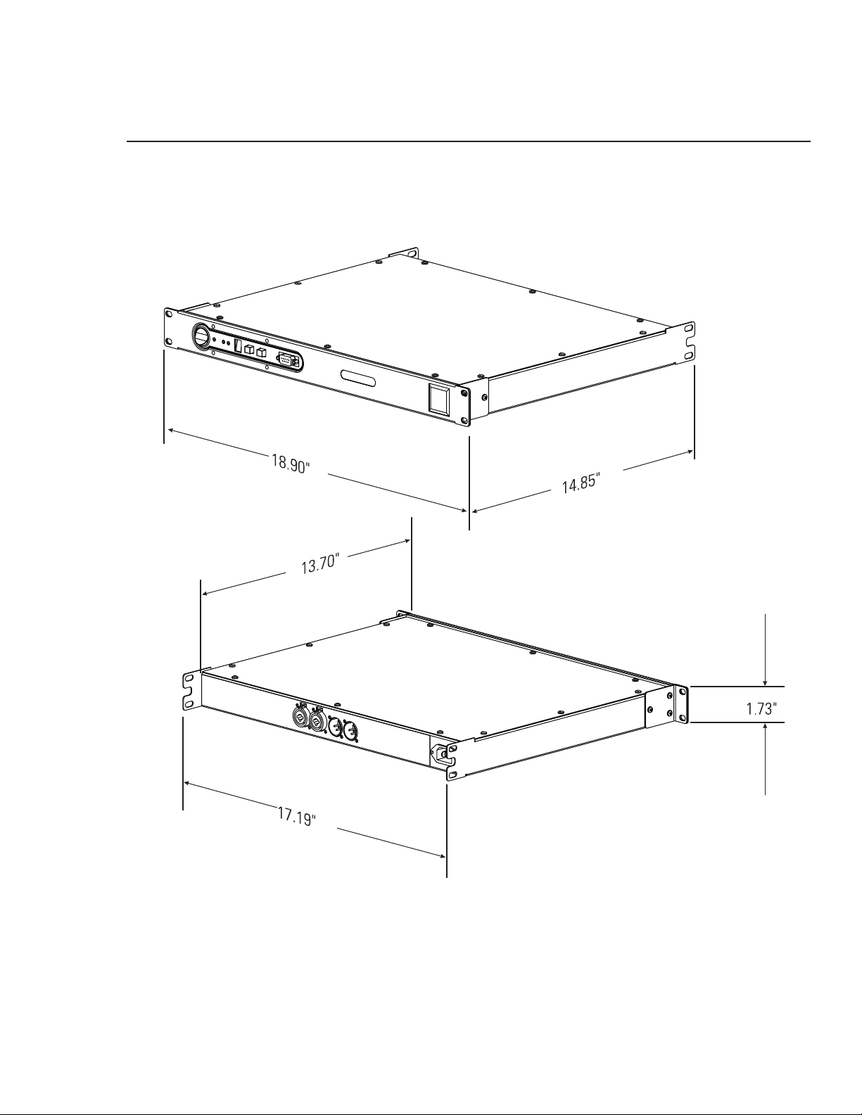
Introduction: Illustrations and Dimensions
Dimensions
5
Installation: Unpacking and Mounting
Unpacking
There are no special unpacking precautions. However, it is recommended you keep the original packing material for reuse
in the rare event that service be required. If service is required and the original packing material is not available, ensure
that the unit is adequately protected for shipment (strong box of appropriate size , sufficient packing material to prevent
load-shifting or impact damage).
What is included in the carton:
Item Description Quantity
1- DSP-30 Digital Signal Processor 1
2- Self-adhesive rubber feet 4
3- Hardware Manual (this document) 1
4- Signal Manager Software CD 1
5- IEC Power Cord 3 x #18 AWG 1
6- RS-232 cable (6 ft.) 1
Mounting
The DSP-30 can be used in or out of an equipment rack. Adhesive rubber feet are included for non-rack mount installations.
Use them to prevent the unit from scratching or marring support surfaces.
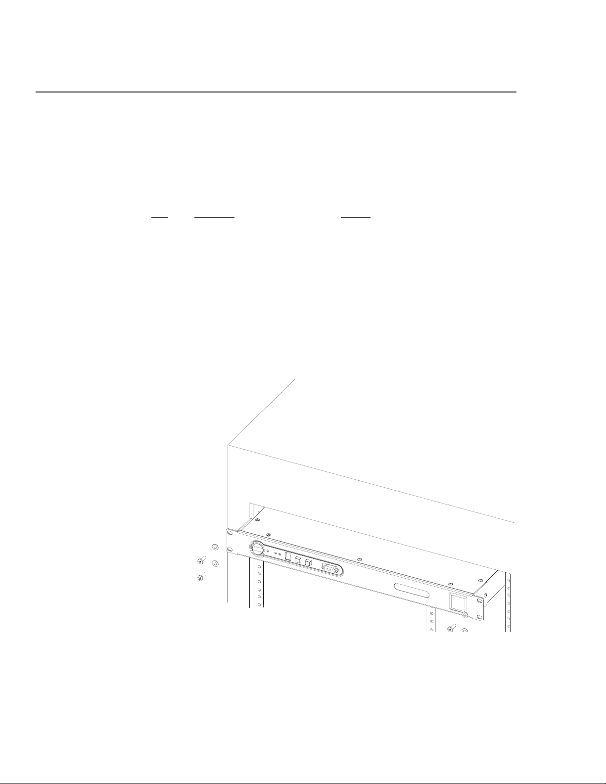
Rack Mounting
Rack mount the DSP-30 by support-
ing it from underneath while align-
ing the mounting holes with the
threaded screw holes in the rails;
install all four mounting screws and
washers and tighten securely. Ensure
use of all four mounting screws in
order to minimize the chance of
bending or distorting the rack mount
ears. Rack mounting is optional.
Support the Rear for Portable/Mobile Installations
If the DSP-30 is to be transported while in a rack, we recommend supporting the rear of the chassis. This will help
prevent the unit from being damaged from the increased mechanical stresses of portable and mobile use. The DSP-
30’s chassis includes integral rear mounting tabs for securing to the rack mounting ears.
6
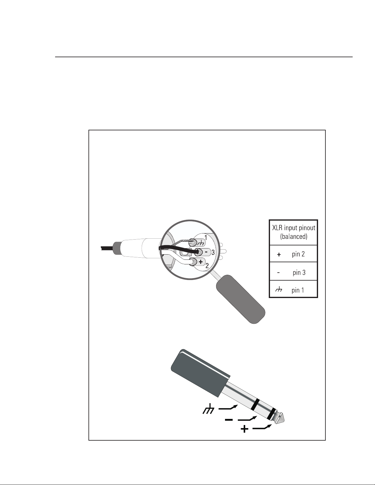
Installation: Balanced Audio Connections
Connecting Audio Inputs and Outputs
All audio connections should be balanced to ensure the best performance. Unbalanced signals may be used if necessary; follow
the wiring guidelines below for recommended unbalanced termination.
The audio input jacks are female 3-pin XLR /TRS “combo” connectors. They will accept male XLR plugs or TRS (tip-ring-sleeve)
1/4-inch phone plugs. The audio output jacks are male 3-pin XLR connectors.
BALANCED
Balanced connection is recommended for all inputs.
The XLR - TRS “combo” inputs are electronically balanced.
Balanced input cables are recommended to minimize noise
pick up and prevent ground loops.
Refer to the pinouts provided (below) for proper connection.
XLR
TRS (1/4 inch)
TRS- tip, ring, sleeve (3
conductors)
Suitable only for inputs.
7
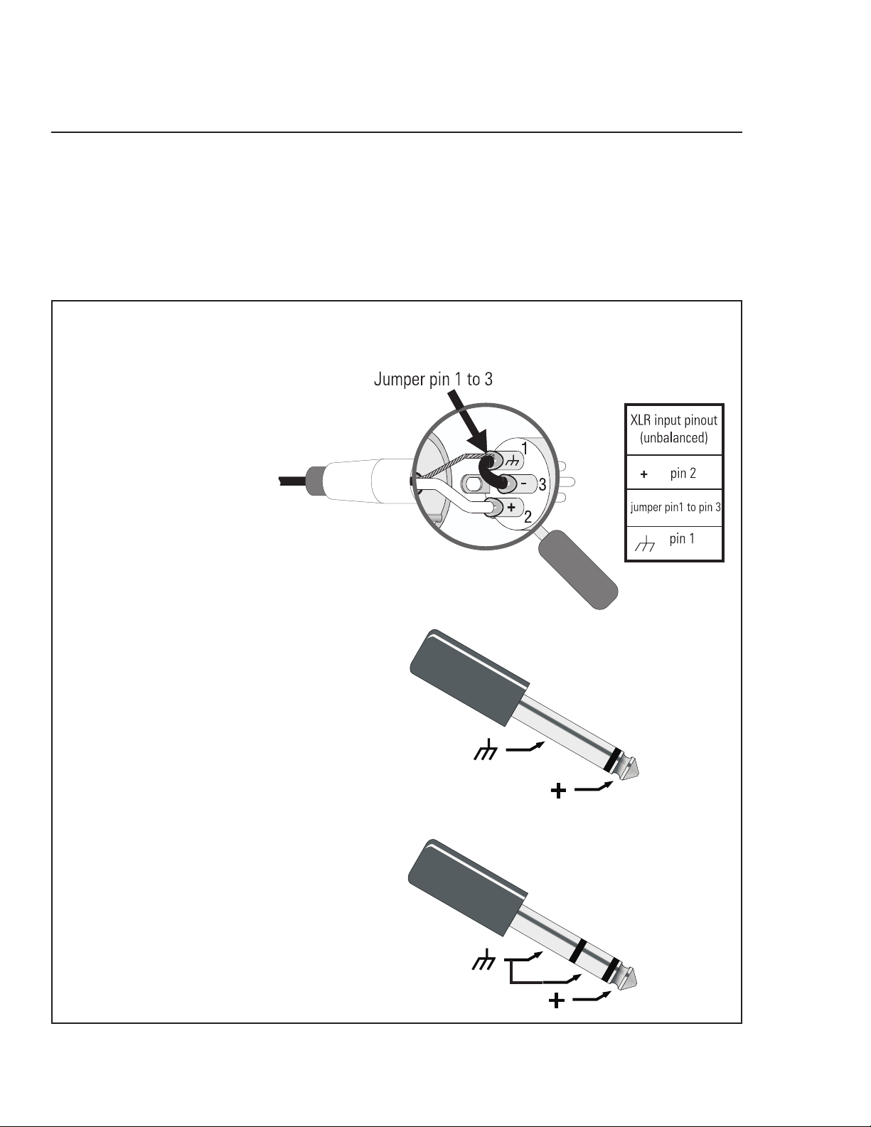
Installation: Unbalanced Audio Connections
Connecting Audio Inputs and Outputs
All audio connections should be balanced to ensure the best performance. Unbalanced signals may be used if necessary; follow
the wiring guidelines below for recommended unbalanced termination.
The audio input jacks are female 3-pin XLR /TRS “combo” connectors. They will accept male XLR plugs or TRS (tip-ring-sleeve)
1/4-inch phone plugs. The audio output jacks are male 3-pin XLR connectors.
UNBALANCED
Unbalanced inputs can be
used if required. If unbal-
anced audio sources are used,
it is preferable to use an ap-
propriate audio transformer (or
other unbalanced-to-balanced
“converter”) to provide a bal-
anced input. If this is not pos-
sible, then it is recommended
that the negative terminal and
shield terminal be connected
to one another with a jumper
wire.
XLR
TS (1/4-inch phone)
This style of plug
automatically connects
the negative terminal to
shield when inserted in
the jack.
TRS (1/4-inch)
NOTE for above abbreviations: TRS- tip, ring, sleeve (3 conductors)
TS- tip, sleeve (2 conductors)
8
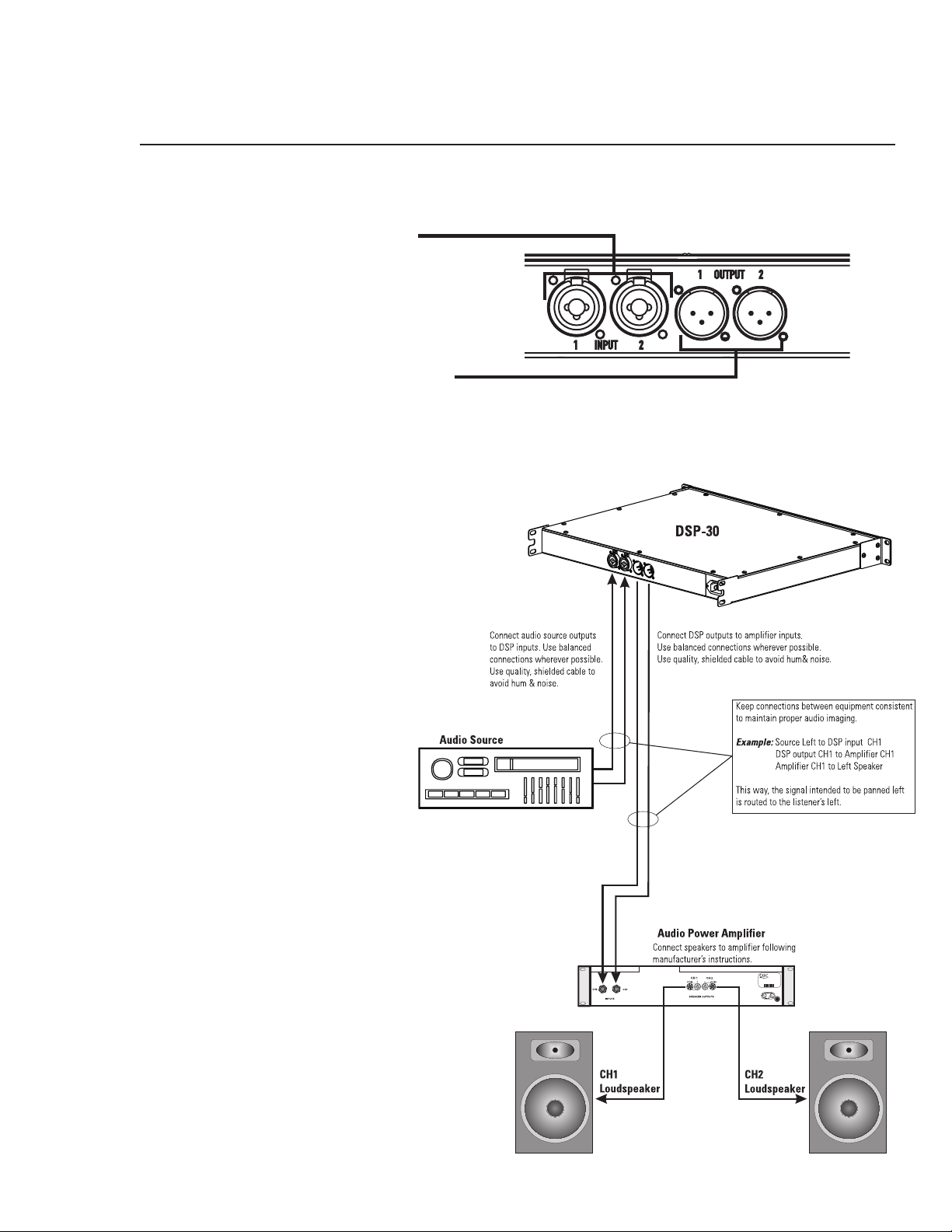
Installation: Connecting Audio Inputs and Outputs
Audio Connections
Once the input and output cables have been properly wired, they can be connected to the receptacles on the rear panel of the DSP-30.
INPUTS- Input jacks are “combo” style. They
accept either male XLR or 1/4-inch diameter TRS
phone plugs. Plug line level audio source into the
input jacks. Use balanced connections wherever
possible.
OUTPUTS- Output jacks are male XLR style. They
accept female XLR plugs. Connect the DSP outputs
to the next audio device in the signal chain (this is
usually a professional audio power amplifier). Use
balanced connections wherever possible.
Basic Audio Connections
Rear Panel Audio
Connections
The basic application shown is representa-
tive of most simple installations. The audio
source outputs (console output, media player)
are connected to the DSP’s input jacks. The
audio program material is processed by the
DSP and sent out the output jacks. Connect
the DSP’s outputs to the next device’s input
jacks. This next device is typically an audio
power amplifier, but can be other signal-
level devices, monitor busses, Ethernet au-
dio devices, etc...
As with all professional audio installations,
use balanced and fully shielded audio con-
nections wherever possible. If connection to
an unbalanced source is neccessary, use an
audio unbalanced-to-balanced converter (au-
dio transformer or active-DI box) to properly
isolate the source. If this is not possible, we
recommend that the unused minus ( - ) termi-
nal be connected to ground (the shield) in
order to minimize noise.
NOTE! AC line cord omitted for clarity. Ensure AC power is properly connected.
9
 Loading...