PVI Industries SU-3 User Manual

INSTALLATION & MAINTENANCE MANUAL
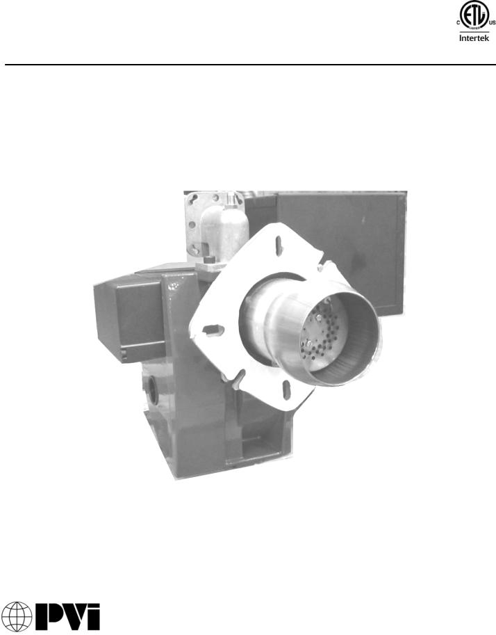
MODEL SU-3 GAS BURNER
Inputs 199,000 thru 399,000 Btu/h (Inputs 58.32 kW thru 116.94 kW)
This burner is for use with Natural Gas or Propane Gas (LP), as specified on the name plate
Installation and service must be performed by a qualified service installer, service agency or the gas supplier.
IMPORTANT: THIS MANUAL CONTAINS INFORMATION REQUIRED FOR INSTALLATION, OPERATION AND MAINTENANCE OF THIS EQUIPMENT. READ AND FOLLOW THE INFORMATION IN THIS MANUAL AND ALL OTHER PROVIDED INSTRUCTIONS, LABELS AND MARKINGS BEFORE INSTALLING, OPERATING OR SERVICING THIS UNIT.
WARNING: If the information and instructions in this manual, the appliance installation and maintenance manual and product markings are not followed exactly, a fire or explosion may result, causing property damage, personal injury or death.
TO THE INSTALLER: These instructions are to be affixed to the burner or to the water heater.
TO THE OWNER: Retain this manual for future reference. These instructions contain important information that will help you in maintaining and operating this appliance.
PVI INDUSTRIES, LLC - Fort Worth, Texas 76111 - Web www.pvi.com - Phone 1-800-433-5654
1
PV500-56 06/12
TABLE OF CONTENTS
1.Safety Considerations
2.Codes
3.Electrical Specifications
4.Combustion and Ventilation Air
4.1Equipment Located in Confined Spaces
4.2Maximum Allowed Remote Combustion Air Inlet Length
4.3Vertical or Horizontal Remote Air Duct Termination
4.4Remote Air Consideration for Combined Remote Air Ducting
5.Venting
6.Gas Supply and Piping
6.1Gas Train and Controls Certification
6.2Gas Control Trains
6.3Inlet Pressure
6.4Manifold Pressure
6.5Gas Service and Pipe Capacity
6.6Gas Piping to Burner
6.7Appliance Isolation During Gas Supply Piping Pressure
7.Sequence of Operation
8.Burner Operation
9.Electrode & Flame Sensor Positioning
10.Burner Setup and Adjustment
10.1Commissioning Checklist
10.2Adjusting Burner Using Combustion Analyzer
10.3Adjusting Burner Head
10.4Burner Operation Record
11.Maintenance Instructions
12.Troubleshooting
13.Materials List
2
PV500-56 06/12

1. SAFETY CONSIDERATIONS
WARNING: If the information in these instructions is not followed exactly, a fire or explosion may result, causing property damage, personal injury or death.
FOR YOUR SAFETY
Do not store or use gasoline or other flammable vapors or liquids in the vicinity of this or any other appliance.
WHAT TO DO IF YOU SMELL GAS
Do not try to light any appliance.
Do not touch any electric switch; do not use any phone in your building.
Immediately call your gas supplier from a location away from your building and the smell of gas. Follow the gas supplier's instructions.
If you cannot reach your gas supplier, call the fire department.
Seasonal or annual combustion check-out by a qualified service agency is recommended to enable continued safe and efficient operation.
AVERTISSEMENT: Assurez vous de bien suivre les instructions données dans cette notice pour réduire au minimum le risque d’incendie ou d’explosion ou pour éviter tout dommage matériel, toute blessure ou la mort.
POUR VOTRE SECURITE
•Ne pas entreposer ni utiliser d’essence ni d’autres vapeurs ou liquides inflammables dans le voisinage de cet appareil ou de tout autre appareil.
QUE FAIRE SI VOUS SENTEZ UNE ODEUR DE GAZ
•Ne pas tenter d’allumer d’appareils.
•Ne touchez à aucun interrupteur. Ne pas vous servir des téléphones dans le bâtiment où vous vous trouvez.
•Appeler immédiatement votre fournisseur de gaz depuis un voisin. Suivez les instructions du fournisseur.
•Si vous ne pouvez rejoindre le fournisseur de gaz, appelez le service des incendies.
L’installation et l´installation et l’entretien doivent être assurés par un installateur ou un service d’entretien qualifie ou par le fournisseur de gaz.
WARNING: Installation, adjustment and maintenance of this burner must be performed in accordance with this manual and with local codes by a qualified service agency. Improper installation, adjustment, alteration, service or maintenance can result in property damage, personal injury or death.
WARNING: Deadly levels of CARBON MONOXIDE can occur if the burner is not properly operating. Verify proper carbon monoxide levels during first operation and commissioning and following any burner, gas supply, heater or venting change or adjustment. Additionally, have combustion checked annually by a qualified service agency. Failure to verify proper carbon monoxide levels can result in property damage, personal injury or death.
WARNING: Improper installation, adjustment, alteration, service or maintenance can cause injury or property damage. Refer to this manual for assistance, or consult a qualified installer.
WARNING: The burner supplied with this water heater must be adjusted and operated on the gas, at the firing rate and pressures shown on the appliance and burner decals. Firing this burner above the allowed firing rate will void the warranty, and may result in improper operation, a fire or explosion, causing property damage, personal injury or death.
3
PV500-56 06/12

2. CODES
The water heater and burner must be installed in accordance with those installation regulations in force in the local area where the installation is to be made. Authorities having jurisdiction must be consulted before installation is made. In the absence of such requirements, the installation shall be in accordance with the instructions in this manual, the water heater Installation and Maintenance manual, appliance markings and supplemental instructions and in compliance with the Standard for Installation of Domestic Gas Conversion Burners and the latest edition of the National Fuel Gas Code, ANSI Z223.1. Where required by the Canadian authority having jurisdiction, the equipment must be installed in accordance with the latest edition of the Installation Code for Gas Burner Appliances and Equipment CAN/CSA B149.1 and/or B149.2 and applicable Provincial Regulations.
3. ELECTRICAL SPECIFICATIONS
SU-3 Electrical Specifications
Primary Electric Input |
Secondary Electric Input |
Total Watts |
Total Amps |
|
|
|
|
120 Volt, 60 Hz, 1 Ph |
24 Volts |
150 Max |
3 or less |
|
|
|
|
Electric Wiring
See appliance rating decal for electrical service requirements. The appliance must be electrically supplied and grounded in accordance with the requirements of the authority having jurisdiction or in the absence of such requirements, with the latest edition of the National Electrical Code ANSI/NFPA No. 70. In Canada, the electrical service must conform to local electrical codes and/or CSA C22.1, Canadian Electrical Code, Part 1.
Connect multi-pin connector at end of flexible conduit from the water heater to the multi-pin plug on the burner control box.
To avoid serious damage, DO NOT energize the unit until the system and appliance is full of water.
The burner is grounded through the electrical connection to the water heater. Be certain the water heater has been properly grounded.
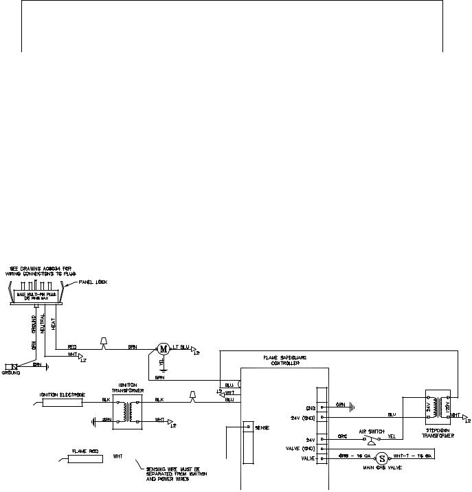
Refer to the burner control wiring diagram below and located inside the burner control cabinet for further information.
Blower Motor - 120 Volt/ 60 Hz/1 Phase, 1/6 HP PSC motor.
SU-3 Wiring Diagram
4
PV500-56 06/12
4.COMBUSTION AND VENTILATION AIR
Provisions for adequate combustion and ventilation air to the mechanical room must be in accordance with Section 5.3 “Air for Combustion and Ventilation” of the latest edition of the National Fuel Gas Code, ANSI Z223.1 and/or CAN/CSA B149, Installation Codes or applicable provisions of the local building codes.
4.1Equipment Located in Confined Spaces
Equipment located in confined spaces requires two openings installed within 12” (30.5 cm) from the top and bottom of the room to assure adequate combustion air and proper ventilation. The total input of all gas utilization equipment installed in the room must be used to determine the required minimum air volume needed for combustion, ventilation and dilution of flue gasses.
All Air From Outdoors:
Each opening requires a minimum free area of 1 square inch (6.45 cm2) per 4000 Btu/hr (1.17 kW) input if
directly communicating with the outdoors or communicating to the outdoors through vertical ducts.
Each opening requires a minimum free area of 1 square inch (6.45 cm2) per 2000 Btu/hr (0.59 kW) input if communicating with the outdoors through horizontal ducts.
All Air From Inside The Building:
Each opening requires a minimum free area of 1 square inch (6.45 cm2) per 1000 Btu/hr (0.29 kW) input, but not less than 100 square inches (0.06 m2).
Combination Of Air From The Indoors And From The Outdoors:
Refer to National Fuel Gas Code, ANSI Z223.1 and/or CAN/CSA B149, Installation Codes or applicable provisions of the local building codes.
WARNING: Adequate clean combustion air must be provided to the appliance. Under no circumstances should the appliance ever be under a negative pressure. Particular care should be taken when exhaust fans, compressors, air handling units, etc. may rob air from the appliance. The combustion air supply must be completely free of any chemical or fumes, which may be corrosive to the appliance. Some common chemical fumes to avoid are fluorocarbons and other halogenated compounds, most commonly present as refrigerants or solvents, such as Freon, trichloroethylene, perchlorethylene, chlorine, etc. These chemicals, when in contact with the equipment or when burned, form acids which quickly attack the tubes, flue collector, stack and other appliance and auxiliary equipment. The result of inadequate clean combustion air or negative pressure can be premature unwarranted product failure or unsafe operation producing carbon monoxide that could escape into the building. Exposure to carbon monoxide can lead to injury or death.
4.2Maximum Allowed Remote Combustion Air Inlet Length (Equivalent Length)
Burners are suitable for use with an optional outside combustion air intake system that may be routed either horizontally or vertically using a field obtained 3” by 4” (7.62 cm by 10.16 cm) increaser and 4 inch (10.16 cm) sealed plastic or metal pipe, extending up to 100 equivalent feet (30.48 equivalent meters). Larger pipe may be used to extend the equivalent length, if the pressure drop is not increased. A UL, ETL, ULC or CSA listed vent cap must be applied to the terminus of the air intake system. The terminus may be either horizontal (from sidewall) or vertical above roof.
The Listed air intake vent termination cap MUST be attached to the remote combustion air vent termination to adequately protect the combustion air inlet from wind and weather. A UL Listed air intake termination cap is available from PVI Industries and may have shipped with the water heater and burner as a purchased option.
4.3Vertical or Horizontal Remote Air Duct Termination
Air inlet and exhaust vents should terminate in the same wind pressure area whenever possible.
Air inlet must be located no less than 3 feet (0.91m) below the exhaust terminal if they are within 10 feet (3.05 m) of each other.
If terminating through the roof, the air inlet must terminate at least 12 inches (0.3 m) above roof level and at least 12 inches (0.3 m) above snow levels.
If terminating through a sidewall, the air inlet must terminate at least 12 inches (0.3 m) above grade and/or at least 12 inches (0.3 m) above normal snow levels.
5
PV500-56 06/12
 Loading...