


INSTALLATION & MAINTENANCE MANUAL
POWER VT PLUS WATER HEATER
MODELS (40, 50, 75, 90, 100) LX 125 A-PVIF
MODELS (50, 75, 90, 100) LX (250, 300) A-PVIF
Installation and service must be performed by a qualified service installer, service agency or the gas supplier.
IMPORTANT: THIS MANUAL CONTAINS INFORMATION REQUIRED FOR INSTALLATION, OPERATION AND MAINTENANCE OF THIS EQUIPMENT. READ AND FOLLOW THE INFORMATION IN THIS MANUAL AND ALL OTHER PROVIDED INSTRUCTIONS, LABELS AND MARKINGS BEFORE INSTALLING, OPERATING OR SERVICING THIS UNIT.
TO THE INSTALLER: After installation, these instructions must be given to the equipment user or left near the appliance. SPECIAL INSTRUCTIONS TO THE OWNER: Retain this manual for future reference. These instructions contain important information that will help you in maintaining and operating this appliance.
PVI INDUSTRIES, LLC - Fort Worth, Texas 76111 - Web www.pvi.com - Phone 1-800-433-5654
1
PV500-44U 06/12
TABLE OF CONTENTS
1.Safety Considerations
2.Standard Features and Equipment
2.1Performance
2.2Pressure Vessel
2.3Heat Exchanger
2.4Code and Standards
2.5Burner, Operating Controls & Safeties
2.6Warranty and Service Policy (see warranty and service policy for details)
2.7Miscellaneous
3.Product Descriptions
4.Water Heater Installation
4.1Checking Equipment Before You Install
4.2Codes
4.3Electrical Requirements
4.4Handling and Location
4.5Service Clearances
4.6Clearances to Combustible Surfaces
5.General Piping Guidelines
5.1Inlet and Outlet Connections
5.2Building Return Piping
6.Condensate Drain, Trap & Disposal
6.1Condensate Neutralization System (optional)
7.Gas Supply and Piping
7.1Gas Train and controls Certification
7.2Gas Control Trains
7.3Inlet Pressure
7.4Manifold Pressure
7.5Gas Piping Size
7.6Appliance Isolation during Gas Supply Piping Pressure Test
7.7Gas Connection
8.Combustion and Ventilation Air
8.1Equipment Located in Confined Spaces
8.2Maximum Allowed Remote Combustion Air Inlet Length
8.3Remote Combustion Air Cap
8.4Vertical or Horizontal Remote Air Duct Termination
8.5Remote Air Consideration for Combined Remote Air Ducting
9.Venting
9.1Venting the Power VT Plus “SANI” Model
9.2Venting the Power VT Plus
9.3Maximum Category IV Vent Length
9.4CPVC Vent System Design, Construction and Assembly
9.5Vertical or Horizontal Vent Termination
9.6Combining Category IV Vents
2
PV500-44U 06/12
10.Operating and Safety Controls
10.1Temperature and Pressure Relief Valve(s)
10.2Operating Temperature Control
10.3High Water Temperature Limit Control
10.4Cathodic Protection
10.5Electronic Low Water Cut-off (optional)
11.TEMPTRAC Electronic Controller Panel
11.1Principal of Operation
11.2Upper LED Readout
11.3Lower LED Readout
11.4Control Buttons
11.5To View the Setpoint
11.6To Change the Setpoint
11.7To Change Other Parameters
11.8LED Display Alarm Messages
12.Remote Connections – Terminal Strip
12.1Making BMS/BAS Remote Connection for Analog and Binary Signals
12.3Terminal Functions
13.Sequence of Operation
14.Initial Startup
14.1Initial Startup Requirements
14.2Tools and Instrumentation Required
14.3Resources
14.4On Site Considerations
14.5Startup Procedure
15.Troubleshooting Guide
16.Replacement Parts
16.1Control Panel
16.2Control Panel Components
16.3Burner Assembly
16.4Burner Assembly Components
17.Periodic Maintenance
18.Recommended Maintenance Schedule
Warranty forms ship separately with each product.
3
PV500-44U 06/12
1 SAFETY CONSIDERATIONS
WARNING: If the information in the supplied manual(s) is not followed exactly, a fire, explosion or exposure to hazardous materials may result, causing property damage, personal injury or loss of life.
FOR YOUR SAFETY
Do not store or use gasoline or other flammable vapors or liquids in the vicinity of this or any other appliance.
WHAT TO DO IF YOU SMELL GAS
Do not try to light any appliance.
Do not touch any electric switch; do not use any phone in your building.
Immediately call your gas supplier from a location away from your building and the smell of gas. Follow the gas supplier's instructions.
If you cannot reach your gas supplier, call the fire department.
Installation and service must be performed by a qualified installer, service agency or the gas supplier.
This product contains, or may come to contain materials that have been identified as carcinogenic, or possibly carcinogenic to humans. Before installing, servicing or removing this product, read and follow the supplied instructions
WARNING: Installation and service must be performed by a qualified installer, service agency or the gas supplier, who must read and follow the supplied instructions before installing, servicing or removing this appliance. Refer to the information contained in this manual. Improper installation, adjustment, alteration, service or maintenance can cause property damage, personal injury, exposure to hazardous materials or loss of life.
WARNING: Do not use this appliance if any part has been under water. Immediately call a qualified service technician to inspect the unit and to replace any part of the control system, all gas controls and all other items affecting safe appliance operation and which has been under water.
WARNING: In an emergency shut the main gas supply valve to the appliance from a location safely away from the emergency. Failure to follow these instructions can cause property damage, personal injury, and exposure to hazardous materials or loss of life.
PRODUCT SAFETY INFORMATION
REFRACTORY CERAMIC FIBER PRODUCT WITH CRYSTALLINE SILICA
WARNING: This product contains or may come to contain crystalline silica, which has been identified by the International Agency for Research on Cancer (IARC) as carcinogenic to humans. This product also contains refractory ceramic fibers, which have been identified by the IARC as possibly carcinogenic to humans. Avoid breathing fiber particulates and dust.
RISKS:
Air borne fibrous insulation is a possible cancer hazard by inhalation.
Airborne crystalline silica may cause silicosis (lung disease) by inhalation.
May cause temporary irritation to eyes, skin, and respiratory tract.
PRECAUTIONARY MEASURES:
Minimize airborne fibers with engineering controls.
Use NIOSH/MSHA approved respirators as required (see MSDS).
Wear long sleeved, loose-fitting clothing, eye protection and gloves.
FIRST AID MEASURES: (If any of the irritations listed persists, seek medical attention)
|
Eyes: |
Flush with water. |
|
Skin: |
Wash with soap and warm water. |
Ingestion: Do not induce vomiting. Get medical attention if gastrointestinal symptoms develop.
Inhalation: Remove to fresh clean air.
WARNING: If you are unfamiliar with the safe handling of refractory ceramic fiber products, or if you wish additional information prior to beginning any disassembly of the water heater or boiler that might expose refractory ceramic fiber materials, contact: Unifrax Corporation, 2351 Whirlpool Street, Niagara Falls, NY 14305-2413, 1-800-322-2293.
IDENTIFICATION OF REFRACTORY CERAMIC FIBER MATERIALS (RCF):
The burner, lower tank and upper and lower flue collector assemblies utilize RCF material. (The RFC materials are located within the product and not generally exposed except during service, disassembly or assembly.)
4
PV500-44U 06/12
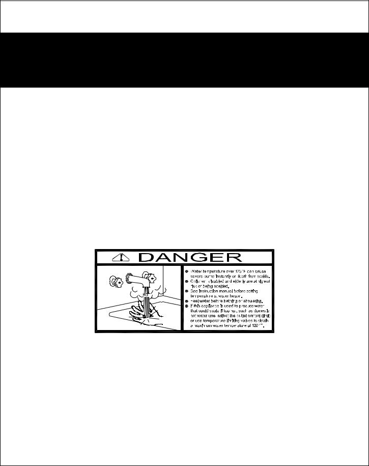
IMPORTANT SAFETY NOTE
It takes only 5 seconds of skin contact with 140°F water to cause a second degree burn! You must protect against high water temperatures at all
lavatories, tubs, showers and other points of hot water contact.
Accidental scalding from high water temperatures is a greater risk in some types of installations. Some examples are:
HOMES FOR THE MENTALLY HANDICAPPED
HOMES FOR THE PHYSICALLY HANDICAPPED
HOSPITALS AND NURSING HOMES
ELDER CARE FACILITIES AND REST HOMES
ORPHANAGES AND CHILD CARE FACILITIES
OTHER INSTALLATIONS - WHERE RESPONSE TO CONTACT WITH HOT WATER MAY BE SLOWER OR WHERE THE DANGER OF HOT WATER CONTACT IS GREATER
Thermostatically controlled mixing valves must be used in the design of the potable hot water system.
Potable hot water should be tempered to no more than 110°F when used for bathing or other personal uses.
Good engineering practice mandates the use of thermostatically controlled mixing valves set at 120°F or less to keep the delivered water temperature
below scalding temperatures.
5
PV500-44U 06/12
2 STANDARD FEATURES AND EQUIPMENT
2.1Performance
98% thermal efficiency at full fire from 40° to 140°F
Up to 99% thermal efficiency with modulation
< 20 ppm NOx (399 to 900 MBH)
Ducts direct combustion air up to 100 equivalent feet through 6-inch diameter material (requires UL approved vent cap, see optional equipment list)
Vents up to 100 equivalent feet through 6-inch diameter material
2.2Pressure Vessel
AquaPLEX tank (unlined duplex alloy)
Storage tank ASME stamped and National Board registered for 150 psi MAWP
Nonferrous, removable fittings at all tank connections
Hand hole cleanout
Fiberglass insulation
Steel jacket panels with industrial-grade finish
Drain valve
2.3Heat Exchanger
Three-pass, fire tube design
AquaPLEX fire tubes
Secondary economizer for low temperature flue gas
2.4Codes and Standards
Intertek / ETL listed to US and Canadian safety standards
Intertek / ETL listed for use with CPVC vent material (SANI models require listed Cat IV SS vent)
Intertek / ETL certified as low-lead compliant
FM compliant
ASHRAE 90.1 compliant
2.5Burner, Operating Controls & Safeties
Pre-mix surface burner with self-adjusting, proportionate gas/air ratio
UL 795 compliant gas train
Electronic flame safeguard with preand post-purge
Combustion sequence panel lights including lockout
Programmable electronic operating control with digital temperature readouts, adjustable from 70°F to 180°F
Immersion temperature limiting device (high limit control)
ASME-rated temperature and pressure relief valve
NEMA-1 control enclosure
Terminals for remote on-off
Flame failure audible alarm and indicating light with remote contacts
Seamless VFD modulation with 7-to-1 turndown
2.6Warranty and Service Policy (see warranty or service policy for details)
10-Year tank warranty (PV 627)
3-Year scale failure warranty (PV 563)
First-year cost-free service policy (PV 551)
10-Year chloride-induced stress corrosion cracking warranty (PV 8083)
2.7Miscellaneous
Factory authorized startup
Vent termination cap, 6-inch diameter (larger cap optional)
Factory-equipped for connection to direct inlet air (requires UL listed vent termination cap, see options list)
Condensate “P” trap (provided for field installation)
6
PV500-44U 06/12

3PRODUCT DESCRIPTION Component, Controls and Connection Locations (Locations May Vary)
125 SERIES
7
PV500-44U 06/12
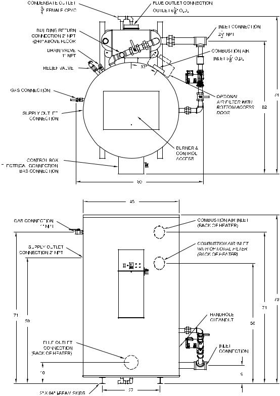
250 SERIES
8
PV500-44U 06/12
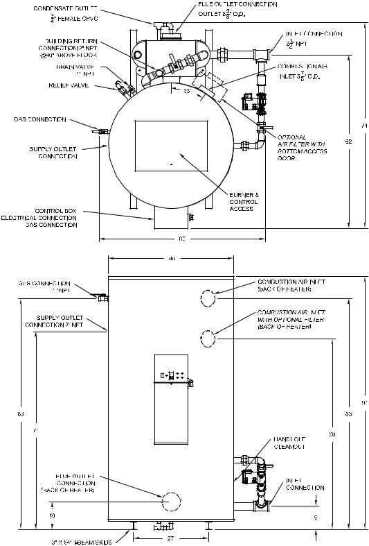
300 SERIES
9
PV500-44U 06/12
4 WATER HEATER INSTALLATION
4.1Checking Equipment Before You Install
Inspect the unit completely upon receipt from the freight carrier before signing the bill of lading. Inspect the appliance and all accompanying parts for signs of impact or mishandling. Verify the total number of pieces shown on packing slips with those actually received. Contact the freight carrier immediately if any damage or shortage is detected.
4.2Codes
The equipment must be installed in accordance with those installation regulations in force in the local area where the installation is to be made. Authorities having jurisdiction must be consulted before installation is made. In the absence of such requirements, the installation shall be in accordance with the instructions in this manual, appliance markings and supplemental instructions and in compliance with the latest edition of the National Fuel Gas Code, ANSI Z223.1. Where required by the Canadian authority having jurisdiction, the equipment must be installed in accordance with the latest edition of the Installation Code for Gas Burner Appliances and Equipment CAN/CSA B149.1 and/or B149.2 and applicable Provincial Regulations. All appliances conform to the latest edition of the ASME Boiler and Pressure Vessel Code, Section IV, Part HLW.
4.3Electrical Requirements
See appliance rating decal for electrical service requirements. The appliance must be electrically supplied and grounded in accordance with the requirements of the authority having jurisdiction or in the absence of such requirements, with the latest edition of the National Electrical Code ANSI/NFPA No. 70. In Canada, the electrical service must conform to local electrical codes and/or CSA C22.1, Canadian Electrical Code, Part 1.
All wiring between the unit and field installed devices must be made with type T copper wire.
Line voltage wire exterior to the appliance must be enclosed in approved conduit or approved metal clad cable.
To avoid serious damage, DO NOT energize the unit until the system and appliance is full of water.
4.4Handling and Location
WARNING: Use industry standard safe rigging methods, such as including the use straps and spreader bars and lifting from the water heater base skid assembly, when attempting to lift or move this product. Failure to follow industry safe rigging methods could result in property damage, serious injury or death.
1Check the data decal on the appliance. Be sure the electrical, water, oil, or gas supply is adequate for the installation.
2Carefully remove all shipping supports and bracing.
3These units are suitable for indoor installation only.
4.Installing the water heater on a 4 inch to 6 inch housekeeping pad is recommended to ensure proper condensate drainage.
5.Locate the unit so that if water connections should leak, water damage will not occur. When such locations are unavoidable, install a suitable drain pan, and plumb pan to ensure adequate drainage in the event of a leak. Under no circumstances is the manufacturer responsible for water damage in connection with this unit, or any of its components. The manufacturer’s warranty does not cover water damage.
6.Protect associated electrical components and electrical connections from water (dripping, spraying, rain, etc.) during appliance operation and service.
7.Place the appliance on a level, non-combustible floor. Concrete over wood is not considered non-combustible.
10
PV500-44U 06/12
8.Do not install on carpet or other combustible floor coverings. If installation over a combustible floor is required, follow these guidelines:
Use a base of hollow clay tile or concrete blocks from 8" to 12" thick and extending 24" beyond the sides.
Place the blocks in line so that the holes line up horizontally to provide a clear passage through the blocks.
Install 1/2” fireproof millboard with a 20-gage sheet metal cover over the block base.
Center the unit on the base. Also follow this procedure if electrical conduit runs through the floor, and beneath the appliance. A field-installed base must meet all local fire and safety code requirements.
4.5Service Clearances
Allow sufficient space to provide adequate clearances on all sides for service and inspection. At least 24” above the water heater is required for filter replacement (if equipped) and burner/gas control service, 18” at left and right sides of the appliance. Optional equipment may increase the clearance requirements. Allow sufficient space for installing and servicing connections such as water, gas, vent, combustion air, electrical, pump and other auxiliary equipment.
4.6Clearances To Combustible Surfaces
Minimum 1” clearance must be provided from any vent surface to adjacent combustible material. The minimum clearances to unprotected combustible material are 24” be provided at the front, 8” be provided at the rear and 8” at top, left and right sides of the appliance.
5 GENERAL PIPING GUIDELINES
5.1Inlet and Outlet Connections
1.Use only non-ferrous water piping and fittings. Do not use galvanized pipe or fittings. Use of ferrous or galvanized pipe or fittings can cause rust to form.
2.Install shut-off valves and unions on the inlet and outlet water piping for servicing. Use caution when threading pipe nipples into tank connections to prevent cross threading, or over-tightening. Always use a back-up wrench on tank nipples when tightening unions, valves, etc.
3.Insulate hot water and return circulation lines. Insulate cold water supply lines if subject to freezing during shutdown periods. Important: Do not use the plumbing connected to the appliance as a ground for welding or any other purpose.
4.Pipe the drain valve to a suitable open drain.
5.2Building Return Piping
To maximize water heater efficiency, connect the building return (≈ 5 gpm) directly to the return fitting located at the rear of the tank.
11
PV500-44U 06/12
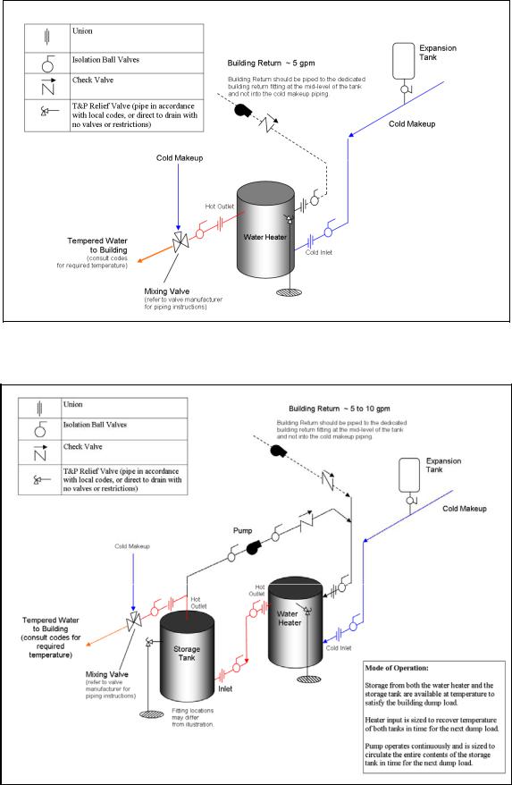
SINGLE WATER PIPING
SINGLE STORAGE WATER HEATER WITH SUPPLEMENTAL STORAGE TANK
12
PV500-44U 06/12
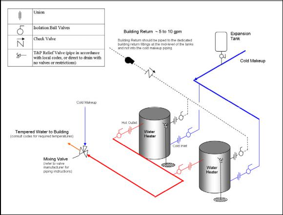
TWO WATER HEATERS WITH REVERSE RETURN PIPING
6CONDENSATE DRAIN, TRAP & DISPOSAL
The POWER VT PLUS water heater is designed to produce significant amounts of condensate because of its high efficiency. Condensate occurs naturally when water vapor in combustion gases is cooled below the dew point. Two 3/4” NPT drain connections are provided. A trap with three inches of standing water below the bottom of the heater (3” above the base of the I-Beam skids), and no higher than the bottom of the heater must be field installed as part of the condensate piping.
WARNING: A trap with three inches of standing water as described in these instructions must be included as part of the condensate piping system. This trap is required to keep hazardous products of combustion from continually entering the room through the condensate piping. Failure to provide this trap can cause, personal injury, exposure to hazardous materials or loss of life.
1.Installing the water heater on a 4 inch to 6 inch housekeeping pad is recommended to ensure proper condensate drainage.
2.Attach a 3/4” CPVC Coupling and Tee to the economizer condensate drain, then use 3/4” CPVC pipe to plumb from the heater condensate outlet to economizer Tee, to a 3” CPVC trap and on to a suitable floor drain or collection system. Each condensing appliance must drain separately. Do not combine condensate drains from multiple condensing appliances into a single drain pipe.
3.Each condensate drain must contain a trap or siphon/pigtail to provide at least 3 inches of standing water, to prevent flue gas flow through the condensate piping. To construct the trap, connect to the 3/4” condensate drain, route the piping downward until the standing water in the trap is not higher than the bottom of the water heater.
4.Install the condensate plumbing as shown in the following diagram.
5.All condensate plumbing must be protected from freezing. Do not locate the condensate piping such that an ice dam of frozen condensate can block the outlet.
13
PV500-44U 06/12
 Loading...