


Model No. PFCCEX01010
Serial No.
Serial
Number
Decal
QUESTIONS?
As a manufacturer, we are committed to providing complete customer satisfaction. If you have questions, or if there are missing parts, please call:
1-888-936-4266
Mon.–Fri. 8h00 until 18h30 EST (excluding holidays).
 CAUTION
Read all precautions and instructions in this manual before using this equipment. Keep this manual for future reference.
USER'S MANUAL


 Visit our website at
www.proform.com

TABLE OF CONTENTS
IMPORTANT PRECAUTIONS . . . . . . . . . . . . . . . . . . . . . . . . . . . . . . . . . . . . . . . . . . . . . . . . . . . . . . . . . . . . .2 BEFORE YOU BEGIN . . . . . . . . . . . . . . . . . . . . . . . . . . . . . . . . . . . . . . . . . . . . . . . . . . . . . . . . . . . . . . . . . . .3 ASSEMBLY . . . . . . . . . . . . . . . . . . . . . . . . . . . . . . . . . . . . . . . . . . . . . . . . . . . . . . . . . . . . . . . . . . . . . . . . . . .4 HOW TO OPERATE THE RECUMBENT CYCLE . . . . . . . . . . . . . . . . . . . . . . . . . . . . . . . . . . . . . . . . . . . . . . .9 MAINTENANCE AND TROUBLESHOOTING . . . . . . . . . . . . . . . . . . . . . . . . . . . . . . . . . . . . . . . . . . . . . . . . .11 CONDITIONING GUIDELINES . . . . . . . . . . . . . . . . . . . . . . . . . . . . . . . . . . . . . . . . . . . . . . . . . . . . . . . . . . . .12 PART LIST . . . . . . . . . . . . . . . . . . . . . . . . . . . . . . . . . . . . . . . . . . . . . . . . . . . . . . . . . . . . . . . . . . . . . . . . . . .14 EXPLODED DRAWING . . . . . . . . . . . . . . . . . . . . . . . . . . . . . . . . . . . . . . . . . . . . . . . . . . . . . . . . . . . . . . . . .15 ORDERING REPLACEMENT PARTS . . . . . . . . . . . . . . . . . . . . . . . . . . . . . . . . . . . . . . . . . . . . . . . .Back Cover LIMITED WARRANTY . . . . . . . . . . . . . . . . . . . . . . . . . . . . . . . . . . . . . . . . . . . . . . . . . . . . . . . . . . .Back Cover
IMPORTANT PRECAUTIONS
 WARNING: To reduce the risk of serious injury, read the following important precautions before using the recumbent cycle.
1.Read all instructions in this manual before using the recumbent cycle.
2.It is the responsibility of the owner to ensure that all users of the recumbent cycle are adequately informed of all precautions. Use the recumbent cycle only as described in this manual.
3.Use the recumbent cycle indoors on a level surface. Keep the recumbent cycle away from moisture and dust. Place a mat under the recumbent cycle to protect the floor.
4.Inspect and properly tighten all parts regularly. Replace any worn parts immediately.
5.Keep children under the age of 12 and pets away from the recumbent cycle at all times.
6.Wear appropriate clothing when exercising; do not wear loose clothing that could become caught on the recumbent cycle. Always wear athletic shoes for foot protection.
7.The recumbent cycle should not be used by persons weighing more than 115 kg (250 lbs.).
8.Always keep your back straight when using the recumbent cycle; do not arch your back.
9.If you feel pain or dizziness while exercising, stop immediately and cool down.
10.The recumbent cycle does not have a frewheel; the pedals will continue to move until the flywheel stops.
11.The pulse sensor is not a medical device. Various factors, including the user's movement, may affect the accuracy of heart rate readings. The pulse sensor is intended only as an exercise aid in determining heart rate trends in general.
12.The recumbent cycle is intended for home use only. Do not use the recumbent cycle in a commercial, rental, or institutional setting.
 WARNING: Before beginning this or any exercise program, consult your physician. This is especially important for persons over the age of 35 or persons with pre-existing health problems. Read all instructions before using. ICON assumes no responsibility for personal injury or property damage sustained by or through the use of this product.
2
BEFORE YOU BEGIN
Congratulations for selecting the new PROFORM® VR 900 EKG recumbent cycle. Cycling is one of the most effective exercises for increasing cardiovascular fitness, building endurance, and toning the entire body. The PROFORM® VR 900 EKG offers an impressive array of features to let you enjoy this healthful exercise in the convenience and privacy of your home.
For your benefit, read this manual carefully before you use the recumbent cycle. If you have questions after reading this manual, please call our Customer
Service Department toll-free at 1-888-936-4266, Monday through Friday, 8h00 until 18h30 Eastern Time (excluding holidays). To help us assist you, please note the product model number and serial number before calling. The model number is PFCCEX01010. The serial number can be found on a decal attached to the recumbent cycle (see the front cover of this manual).
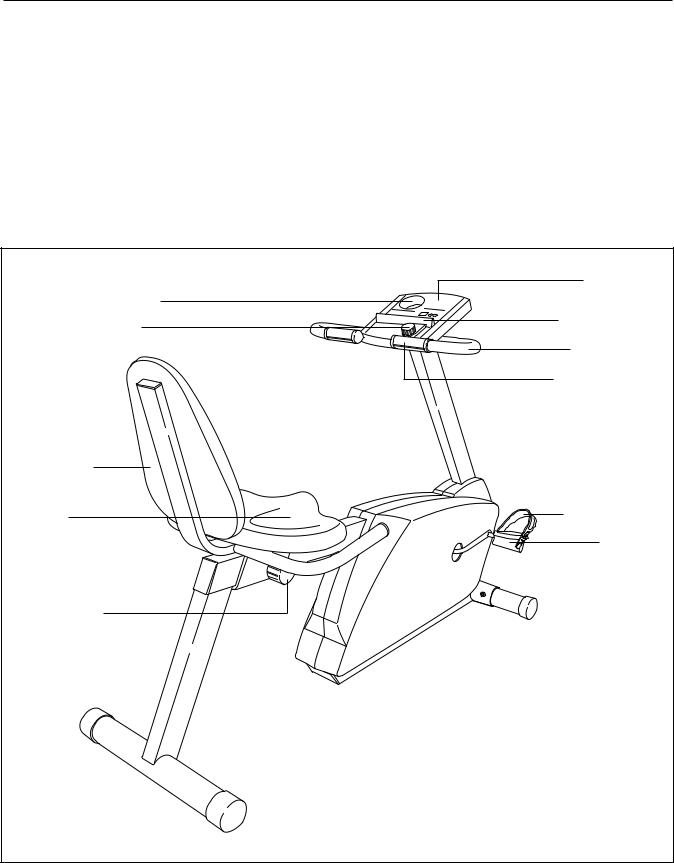
Before reading further, please familiarize yourself with the parts that are labeled in the drawing below.
|
Console |
Water Bottle Holder* |
|
Resistance Knob |
Book Holder |
|
|
|
Handlebar |
|
Pulse Sensor |
|
FRONT |
Backrest |
|
Seat |
Pedal Strap |
|
Pedal |
Seat Knob |
|
REAR |
|
|
RIGHT SIDE |
*No water bottle |
|
is included |
|
|
3 |
ASSEMBLY
Assembly requires two persons. Place all parts of the recumbent cycle in a cleared area and remove the packing materials. Do not dispose of the packing materials until assembly is completed.
Assembly requires the included tools and your own adjustable wrench 
 and Phillips screwdriver
 .
.
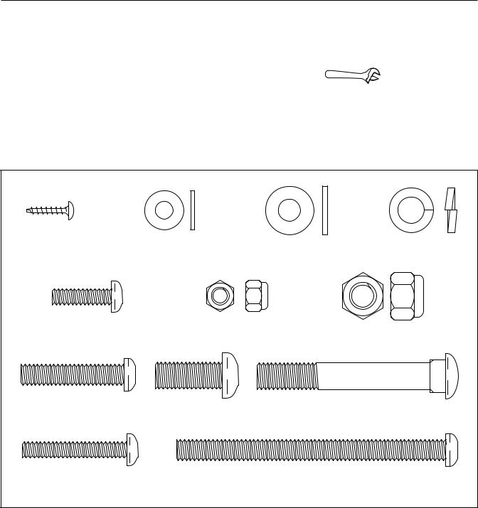
Use the part drawings below to identify the small parts used in assembly. The number in parenthesis below each drawing refers to the key number of the part, from the PART LIST on page 14. The second number refers to the quantity needed for assembly. Note: Some small parts may have been pre-attached for shipping. If a part is not in the parts bag, check to see if it has been pre-attached.
M4 x 16mm |
M6 Washer (54)–3 |
M8 Washer (55)–7 |
M10 Split |
|
Screw (21)–7 |
|
|
|
Washer (17)–10 |
M6 x 22mm Button |
M6 Nylon |
|
M10 Nylon |
|
Screw (29)–4 |
Locknut (15)–4 |
|
Locknut (45)–2 |
|
M8 x 38mm Button |
M10 x 25mm Button |
|
M10 x 75mm Carriage Bolt (72)–2 |
|
Screw (24)–4 |
Screw (71)–10 |
|
|
|
M6 x 38mm Button |
|
M8 x 100mm Button Screw (63)–3 |
||
Bolt (14)–7 |
|
|
|
|
4
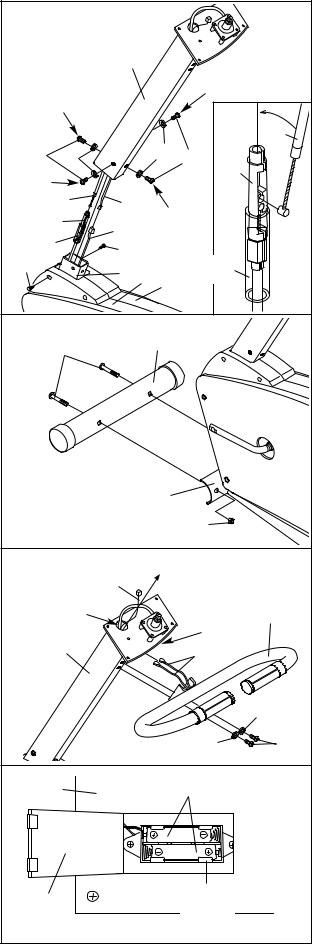
1.While another person holds the Upright (6) in the position shown, connect the Extension Wire (18) to the Reed Switch Wire (20). Refer to the inset drawing. Make sure that the plastic sheath is in the location shown. Insert the tip of the Resistance Cable (22) into the indicated opening in the Cable Connector (69). Then, pull up on the Resistance Cable and insert it into the top of the Cable Connector. Center the sheath on the Cable Connector.
Carefully slide the Upright (6) onto the Frame (1). Be careful to avoid pinching the wires and cables.
Loosely thread four M10 x 25mm Button Screws (71) with M10 Split Washers (17) through the Upright and into the Frame. Secure the tops of the Side Shields (4, 5) with two M4 x 16mm Screws (21). Firmly tighten the four Button Screws in the following order: front, rear, and then sides.
2.Attach the Front Stabilizer (2) to the Frame (1) with two M10 x 75mm Carriage Bolts (72) and two M10 Nylon Locknuts (45).
3.While another person holds the Handlebar (16) near the Upright (6), route the Pulse Wires (33) up through the two indicated holes in the Upright.
Attach the Handlebar (16) to the Upright (6) with two M10 x 25mm Button Screws (71) and two M10 Split Washers (17). Do not tighten the Button Screws yet. Make sure that no wires are pinched between the Handlebar and the Upright.
4.The Console (9) requires two “AA” batteries (not included). Alkaline batteries are recommended. To install batteries, turn the console over, open the battery door, and insert two batteries into the battery clip as shown. Make sure that the negative ends of the batteries (marked “—”) are touching the springs in the battery clip. Close the battery door.
1 |
|
|
|
|
|
|
|
|
|
6 |
|
|
|
|
|
|
|
|
|
|
Side |
|
|
Front |
|
|
|
|
|
|
|
|
|
|
|
|
|
|
22 |
71 |
17 |
|
|
17 |
71 |
69 |
|
Side |
|
|
|
|
|
|
|
|
|
|
|
|
|
|
|
22 |
18 |
|
Rear |
|
|
||
69 |
|
|
|
|
|||
|
20 |
|
|
|
|||
|
|
|
|
|
|
||
Sheath |
|
|
|
|
|
|
|
|
21 |
|
|
|
|
|
|
21 |
|
|
|
|
|
|
|
|
1 |
4 |
|
Sheath |
|
||
|
|
|
|
||||
|
|
5 |
|
|
|
||
|
|
|
|
|
|
|
|
2 |
|
|
|
|
|
|
|
72 |
|
|
2 |
|
|
|
|
|
|
|
|
|
|
||
|
|
|
|
1 |
|
|
|
|
|
|
|
|
45 |
|
|
3 |
|
|
|
|
|
|
|
|
|
18 |
|
|
|
|
|
Hole |
|
|
|
|
|
16 |
|
|
|
|
|
|
Hole |
||
|
|
|
|
|
|
||
6 |
|
|
|
|
33 |
|
|
|
|
|
|
|
|
|
17 |
|
|
|
|
|
17 |
|
71 |
4 |
|
|
|
Batteries |
|
|
|
9 |
|
|
|
|
|
||
Battery |
|
|
|
|
Battery |
|
|
|
|
|
|
Clip |
|
|
|
Door |
|
|
|
|
|
|
|
|
|
|
|
|
|
|
|
5
 Loading...