


C956i
Table of contents
 Loading...
Commercial Treadmill Owner’s Manual
COMMERCIAL PRODUCTS DIVISION

COMMERCIAL PRODUCTS DIVISION
IMPORTANT SAFETY INSTRUCTIONS
When using the C956i or C954i treadmill, always follow basic precautions, including the
following:
• To ensure your safety and to protect the unit, read all the instructions before assembling and using the treadmill.
• To ensure the proper use and safety of the treadmill, make sure that all users read
this manual. Please make this manual a part of your club’s training program.
Remind the club users that before beginning any fitness program, they should
obtain complete physical examinations from their physicians.
Il est conseillé de subir un examen médical complet avant d’entre-prendre tout
programme d’exercise. Si vous avez des étourdissements ou des faiblesses, arrêtez
les exercices immédiatement.
DANGER —
WARNING —
• Do not allow children or those unfamiliar with its operation on or near the treadmill.
Do not leave children unsupervised around the treadmill.
• Never leave the treadmill unattended. Unplug the unit from the power outlet when it
is not in use, before cleaning it, and before putting on or taking off parts. Do not
adjust the running belt when someone is standing on the unit.
• Assemble and operate the treadmill on a solid, level surface. Locate the treadmill a
few feet from walls or furniture. (The minimum space requirement is one meter by two
meters directly behind the running belt.) Check the unit before each use and verify
that all fasteners are secure. Maintain the treadmill in good working condition.
• Use the treadmill only for its intended use as described in this manual. Do not use
accessory attachments that are not recommended by the manufacturer; such attachments might cause injuries.
• If you purchased the optional chest strap, review the guidelines found in the
Heart Rate Option Owner’s Manual
• Never operate the unit if it is damaged, if it is not working properly, if it has been
dropped, or if it has been dropped in water. Return the unit to a service center for
examination and repair.
• Keep all electrical components such as the motor, power cord, and I/O switch, away
from liquids to prevent shock. Do not set anything on the handrail, display console,
or hood. Place liquids, magazines and books in the appropriate receptacles.
• Keep the power cord away from heated surfaces.
• Do not operate the treadmill where aerosol (spray) products are being used or where
IMPORTANT SAFETY INSTRUCTIONS
oxygen is being administered.
• Do not use outdoors.
• The security clip must be attached at waist level prior to beginning a workout. A
cord connects the security clip to the red STOP button on the console. If a user
encounters difficulties, a strong tug on the security cord or a quick tap on the red
STOP button will stop the running belt.
To reduce the risk of electrical shock, always unplug the unit from its
power source before cleaning or performing any maintenance tasks.
To reduce the risk of burns, fire, electric shock, or injury to
persons, take the following precautions:
that is supplied with that option.
Precor
page 2
SAVE THESE INSTRUCTIONS

COMMERCIAL PRODUCTS DIVISION
IMPORTANT SAFETY INSTRUCTIONS
• Use care when getting on or off the treadmill. Use the stationary handrail and straddle
the running belt. Step onto the running belt when the speed is at or below 1 mph
(1.5 kph).
• Never step off the treadmill while the running belt is moving. Keep your body and
head facing forward. Never attempt to turn around on the treadmill.
• Never turn ON the treadmill when someone is standing on the machine.
• Never block the air openings on the hood while operating the treadmill. Keep the air
openings clean and free of lint, hair, or anything that might impeded the free flow of
air. Never drop or insert objects into any opening.
• Wear proper exercise clothing and shoes during a workout—no loose clothing. Tie
long hair back. Keep all loose towels away from the running surface. The running
belt will not stop immediately if an object becomes caught in the belt or rollers.
• Do not rock the unit. Do not stand on the display console or hood.
• Do not overexert yourself or work to exhaustion. If you feel any pain or abnormal
symptoms, stop your workout immediately and consult your physician.
PASSWORD SECURITY
To help prevent unauthorized use, the treadmill is equipped with password protection. The
password involves entering three keys in sequence. If the correct keys are not pressed within
two minutes, further access is denied and the running belt will not move. For more information, refer to
Club Information
.
MAXIMUM USER WEIGHT
You should not allow runners over 160 kg or walkers heavier than 225 kg on the treadmill.
SAFETY APPROVAL
When identified with the ETL-c logo, the treadmill has been tested and conforms to the requirements of CAN/CSA-E-335-1/3-94, Safety of Household and Similar Electrical Appliances.
IMPORTANT SAFETY INSTRUCTIONS
SAVE THESE INSTRUCTIONS
page 3
COMMERCIAL PRODUCTS DIVISION
GROUNDING INSTRUCTIONS
The C956i or C954i treadmill must be grounded. If it should malfunction or break down, grounding provides a path of least resistance for electric current which reduces the risk of electrical
shock. The C956i or C954i treadmill is equipped with a power cord having an equipment-grounding conductor and a grounding plug. The plug must be inserted into an appropriate outlet that is
properly installed and grounded in accordance with all local codes and ordinances Refer to
Diagram 1. If you do not follow these
Warranty.
Grounding Instructions
, you could void the Precor Limited
DANGER —
cian or service person if you are in doubt as to whether the treadmill is properly grounded.
Do not modify the plug provided with the treadmill or use an adapter. If the plug doesn’t
fit the outlet, get a proper outlet installed by a qualified technician.
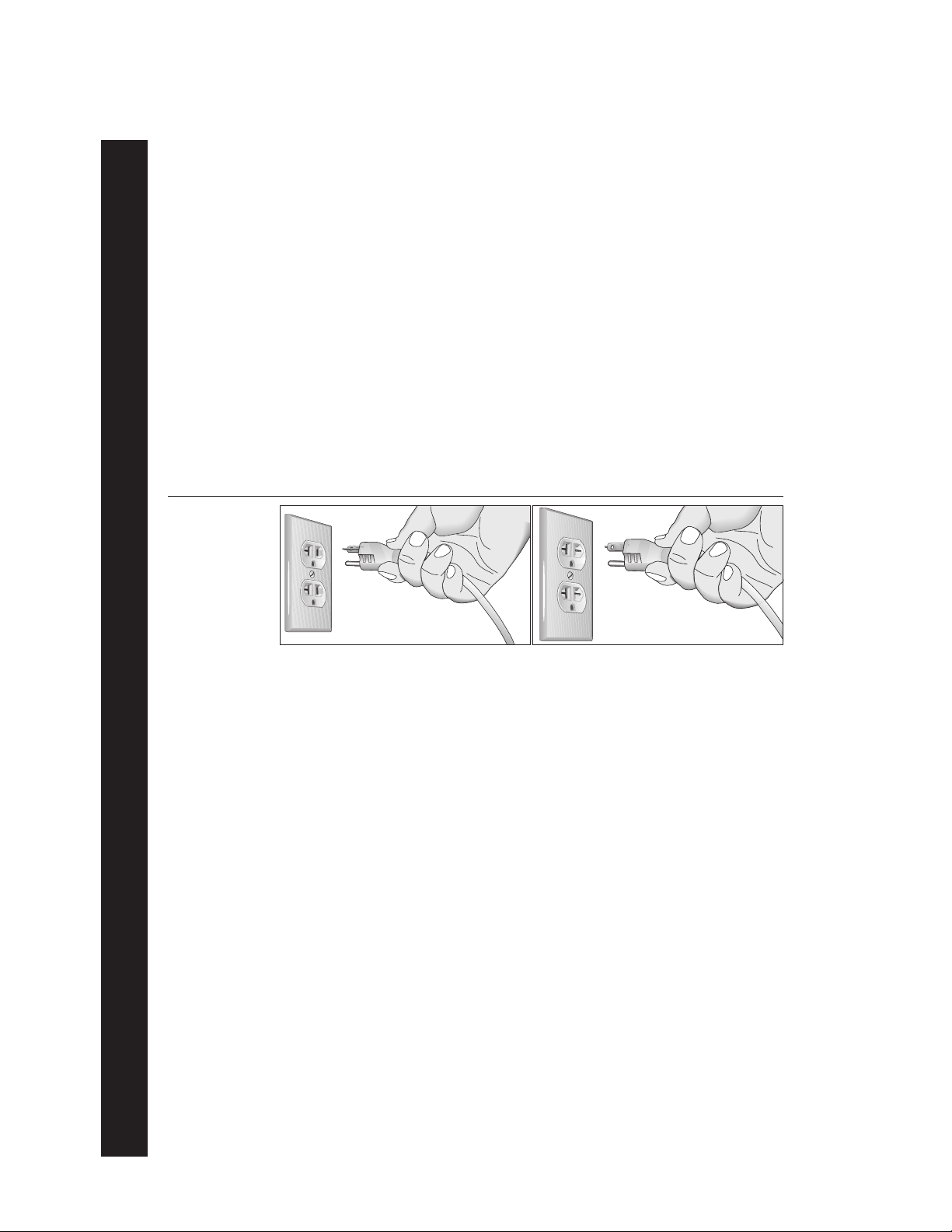
Diagram 1
Correct power
outlet for U.S.
Markets:
120-volt and
240-volt plugs.
120-volt grounding plug 240-volt grounding plug
120V Units and 240V Units Designated for U.S. Markets
The C956i or C954i treadmill must be connected to a dedicated, grounded circuit. A 20 amp
dedicated circuit is recommended.
Improper connection of the equipment-grounding conductor can
result in a risk of electric shock. Check with a qualified electri-
IMPORTANT SAFETY INSTRUCTIONS
page 4
SAVE THESE INSTRUCTIONS

COMMERCIAL PRODUCTS DIVISION
Table of Contents
Important Safety Instructions ................................................................ 2
Password Security ................................................................................................ 3
Maximum User Weight ......................................................................................... 3
Safety Approval .................................................................................................... 3
Grounding Instructions .........................................................................................4
Radio Frequency Interference (RFI) .....................................................................7
European Applications ......................................................................................... 7
Obtaining Service ................................................................................................. 8
About this Manual ................................................................................................. 8
Unpacking the Treadmill ......................................................................... 9
Standard Equipment ............................................................................................. 9
Other Equipment .................................................................................................. 9
Hardware Kit .......................................................................................................10
Setting Up the Treadmill........................................................................ 11
Installation Requirements ................................................................................... 11
Additional tools needed ......................................................................................11
Assembly Instructions ........................................................................................11
Turning the Unit ON and OFF .............................................................................21
Checking the Alignment of the Running Belt ......................................................21
Club Information.................................................................................... 22
Treadmill Location within the Club ...................................................................... 22
Weight Limitations ..............................................................................................22
Changing the Club Settings ................................................................................22
Selecting the Language ...................................................................................... 24
Determining the Units of Measure ......................................................................24
Selecting Password Protection ...........................................................................24
Determining the Club SPEED Limit ....................................................................25
Setting a Workout Time Limit ..............................................................................25
Setting a Pause Time Limit .................................................................................25
Setting a Cool Down Time Limit ......................................................................... 25
Removing or providing a fitness test .................................................................. 26
Changing the C956i Custom Programs ..............................................................26
Viewing the Odometer, Hours of Use, Software
Version and Error Log ........................................................................................ 27
Using CSAFE Standard Equipment .................................................................... 28
page 5

COMMERCIAL PRODUCTS DIVISION
Table of Contents
The C956i/C954i Display ....................................................................... 29
Features on the Display Console ....................................................................... 29
Top Display Windows.......................................................................................... 30
Upper Display (C956i only).................................................................................30
Center Display (C956i and C954i) ......................................................................30
Keys on the Display Console .............................................................................. 32
Keypad Tips........................................................................................................ 32
Exercising on the Treadmill .................................................................. 36
Using the Security Clip .......................................................................................36
Entering a Password .......................................................................................... 36
Pause, Cool Down, Summary and Exit Features ............................................... 36
Quick Steps to Working Out ............................................................................... 38
Workout Tips ...................................................................................................... 38
Cooling Down After a Workout ........................................................................... 40
Programs................................................................................................ 41
The Heart Rate Feature ..................................................................................... 41
Using the SmartRate Feature .............................................................................41
Manual Mode and the QUICKSTART Key ..........................................................43
C956i Track Course ............................................................................................43
Programs with Preset Inclines ............................................................................ 43
C956i Interval Program ...................................................................................... 44
C956i Custom Programs ....................................................................................45
Random Program ...............................................................................................45
C956i Heart Rate Program ................................................................................. 45
C956i Weight Loss Program ............................................................................... 46
C956i Goal-based Programs .............................................................................. 47
Fitness Test ........................................................................................................ 47
Fitness Test Guidelines ............................................................................... 47
Maintenance........................................................................................... 49
Inspection ...........................................................................................................49
Cleaning the Equipment .....................................................................................49
Aligning and Adjusting the Running Belt ............................................................ 50
Storing the Chest Strap ......................................................................................51
Servicing the Treadmill ....................................................................................... 51
Long Term Storage .............................................................................................51
Warranty Registration Card ................................................................................ 53
Precor Limited Warranty .....................................................................................55
Specifications ....................................................................................... back cover
page 6

COMMERCIAL PRODUCTS DIVISION
RADIO FREQUENCY INTERFERENCE (RFI)
Federal Communications Commission Part 15
The treadmill has been tested and found to comply with:
• The IEC EMC Directive (international electromagnetic compatibility certification)
• The limits for a Class A digital device, pursuant to Part 15 of the FCC Rules.
These limits are designed to provide reasonable protection against harmful
interference in a commercial installation. The treadmill generates, uses, and
can radiate radio frequency energy and, if not installed and used in accordance with the owner’s manual instructions, may cause harmful interference
to radio communications. Operation of the treadmill in a residential area is
likely to cause harmful interference. If this occurs, the user will be required to
correct the interference at his or her own expense.
CAUTION —
Per FCC rules, changes or modifications to the
treadmill not expressly approved by Precor, could
void the user’s authority to operate the equipment.
Canadian Department of Communications
This digital apparatus does not exceed the Class A limits for radio noise emissions
from digital apparatus set out in the Radio Interference Regulations of the Canadian
Department of Communications.
Le présent appareil numérique n’émet pas de bruits radioéélectriques dépassant les
limites applicables aux appareils numériques de la Class A prescrites dans le
Règlement sur le brouillage radioélectrique édicté par le ministére des Communications du Canada.
EUROPEAN APPLICATIONS
This treadmill is a Class S/B certified machine according to EN957-1,6 standards.
This treadmill conforms to the requirements of the European Council Directive
89/336/EEC,
standards:
EN55022, Limits & Methods of Measurement of Radio Interference, Information
Technology Equipment. Per the standard, the treadmill is a Class A product. In a
domestic environment, this product may cause radio interference, in which case
the user is responsible to take adequate measures to alleviate the interference.
Electromagnetic Compatibility
and has been tested to the following
EN50082-1, Generic Immunity Standard for Residential, Commercial and Light
Industrial Products.
This treadmill additionally conforms to the requirements of the European Council
Directive 73/23/EEC,
standard:
IEC 335-1, Safety of Household and similar Electrical Appliances.
Low Voltage Directive
and has been tested to the following
page 7

COMMERCIAL PRODUCTS DIVISION
OBTAINING SERVICE
Do not attempt to service the treadmill yourself except for the maintenance tasks
described in this manual. The treadmill does not contain any user-serviceable parts.
For information about product operation or service, visit the Precor Web Site at
www.precor.com or contact an authorized Precor Commercial Products Customer
Support Representative at 1-888-665-4404.
To help customer support personnel expedite your call, have your serial number
available. The serial number can be found on the shipping container or on the label
near the power receptacle. If you have any questions regarding the treadmill, use
the model and serial numbers whenever you call a Precor dealer or Commercial
Products Customer Support Representative.
Model number: C956i or C954i
Unit number: _____ Serial number: ______________________________
Unit number: _____ Serial number: ______________________________
Unit number: _____ Serial number: ______________________________
ABOUT THIS MANUAL
This manual includes instructions for installing and using the treadmill. To maximize
the use of the treadmill, please study this manual thoroughly. The manual uses the
following conventions for identifying special information:
Note: Contains additional information.
Important: Indicates information to which you should pay special attention.
CAUTION: Indicates steps or information necessary to prevent harm to your-
self or damage to the equipment.
WARNING:
equipment and injuries to yourself.
DANGER:
Provides instructions to prevent electrical damage to the
Indicates steps you must take to prevent electrical shock.
page 8

COMMERCIAL PRODUCTS DIVISION
Unpacking the Treadmill
Thank you for purchasing the Precor C956i or C954i treadmill. Built to the exacting
standards of the health club environment, the treadmill is intended for commercial
use and can withstand the rigors of daily club use with little maintenance.
Important: Before using the treadmill, we urge you to familiarize yourself and
your staff with the entire Owner’s Manual. Understanding this manual will help
you and your customers use the treadmill safely and successfully.
CAUTION: This unit weighs over 350 pounds (158 kilograms). To prevent injury
to yourself or damage to the equipment, obtain appropriate assistance before
removing the unit from the pallet.
The treadmill is carefully inspected before shipment so it should arrive in good
operating condition. Precor ships the unit in the following pieces:
❑ Base frame assembly with hood ❑ Two handrails (left and right)
❑ Two upright supports ❑ Hardware kit
❑ Display console with cable ❑ Owner’s Manual
If any items are missing, refer to
STANDARD EQUIPMENT
The treadmill incorporates the Precor SmartRate® and Heart Rate features into its
display console. Devices, such as FitLinxx®, that are CSAFE compatible, can also
be attached.
The Precor heart rate feature is standard on the C956i and provides electrode
strips, called “grips,” on the center handrail. When a user grasps the metal
portion of the center handrail, a heart rate is transmitted to the receiver.
Note: If a user does not wish to use the touch-sensitive hand grips, an optional
chest strap can be purchased and worn. The chest strap transmits the user’s
heart rate and it appears as a number in the Heart Rate display.
Important: The Precor “touch” heart rate is not available on the C954i treadmill,
but the SmartRate and heart rate features will appear on the display if the user
wears the optional chest strap.
Password security is standard on the treadmill. Club patrons have two minutes to
enter a specific key sequence before the running belt will move. For more information, refer to
Club Information
OTHER EQUIPMENT
Obtaining Service
.
.
Optional equipment available through your dealer includes:
• Chest strap.
• Long handrails.
If you are interested in obtaining Precor option kits for your unit, check with your
dealer. For customer support, see
Obtaining Service
.
page 9
COMMERCIAL PRODUCTS DIVISION
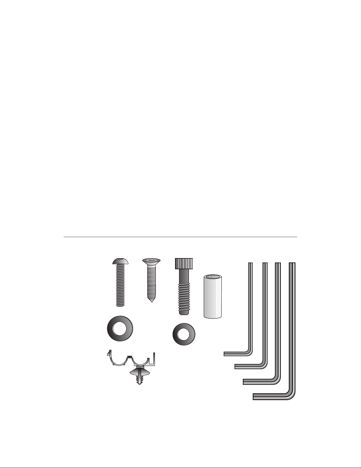
HARDWARE KIT
After unpacking the treadmill, open the hardware kit and make sure that you have
the following items shown in Diagram 2.
❑ (A) twelve 1-inch buttonhead hex screws
❑ (B) sixteen stainless steel washers — place on 1-inch screws
❑ (C) four ⁵⁄₈-inch flat head hex screws — attach to upper handrails
❑ (D) four 3¹⁄₂-inch socket head screws — install upright supports
❑ (E) four black washers — fasteners for upright supports
❑ (F) four barrel spacers — place on 3¹⁄₂-inch socket head screws after washers
❑ (G) ⁵⁄₃₂-inch hex key — attach handrails to display frame
❑ (H) ³⁄₁₆-inch hex key — attach hood, mount upright supports, attach display
and handrails to base frame
❑ (J) ¹⁄₄-inch hex key — attach upright supports to base mounting brackets
Diagram 2
❑ (K) ⁵⁄₁₆-inch hex key — adjust running belt
❑ (L) six power cord clips
Hardware kit (not shown to scale).
A
C
D
B
E
L
F
G
H
J
K
page 10
Note: After assembling the treadmill, be sure to store the hex keys in a secure
place. The tools are used for specific maintenance procedures that are described
in this manual.

COMMERCIAL PRODUCTS DIVISION
Setting Up the Treadmill
You do not need any special knowledge or experience to set up the treadmill.
However, because of its size and weight, you will need to obtain assistance.
INSTALLATION REQUIREMENTS
Follow these installation requirements when installing the treadmill.
If you do not
install the treadmill according to the following guidelines, you could void the Precor
limited warranty.
• Set up the treadmill on a solid, flat surface. Unpack and assemble the tread-
mill close to where you plan to use it. Make sure that the flat surface under the unit
is smooth and level. A level unit is required for the user’s safety and proper operation.
• Provide ample space around the unit. It is important to keep the area
around the treadmill open and free from encumbrances. The minimum space
requirement needed for user safety and proper maintenance is one meter
by two meters square, directly behind the running belt.
• Fill out and mail the limited warranty card. The serial number can be found
on the shipping container or on the label near the power receptacle. Write the
serial number onto the Precor limited warranty card found on the back cover of
this manual and in the
• Use the appropriate voltage, dedicated circuit, and grounding as speci-
fied on the treadmill. The treadmill is available in both 120-volt and 240-volt
models. Refer to the treadmill’s identification label to determine the voltage
that your treadmill requires. Both the 120-volt and 240-volt models require a
dedicated circuit. A 20 amp circuit is recommended.
CAUTION: Do not use a non-grounded outlet or transformer. Do not
remove or otherwise bypass the plug with an adapter. Electrical damage
can occur and void the Precor limited warranty if the treadmill is
connected to an improper power source. Refer to
Obtaining Service
section.
Grounding Instructions
.
ADDITIONAL TOOLS NEEDED
Obtain the following tools
❑ Wire cutter ❑ Medium weight string
❑ Bubble level ❑ ¹⁄₂-inch box end wrench
❑ SAE standard socket set with a ratchet or 8-inch crescent wrench
before
ASSEMBLY INSTRUCTIONS
Take the following steps to assemble the treadmill.
CAUTION: To avoid injury and ensure your safety, get assistance
before moving the treadmill off the pallet. Do not drop the unit.
1. Think about the site and location. Have your assistants help place the shipping
carton close to the location where you plan to use the treadmill. Break down the
side walls of the shipping carton so that they lie flat. Remove the loose contents.
assembling the treadmill.
page 11
COMMERCIAL PRODUCTS DIVISION
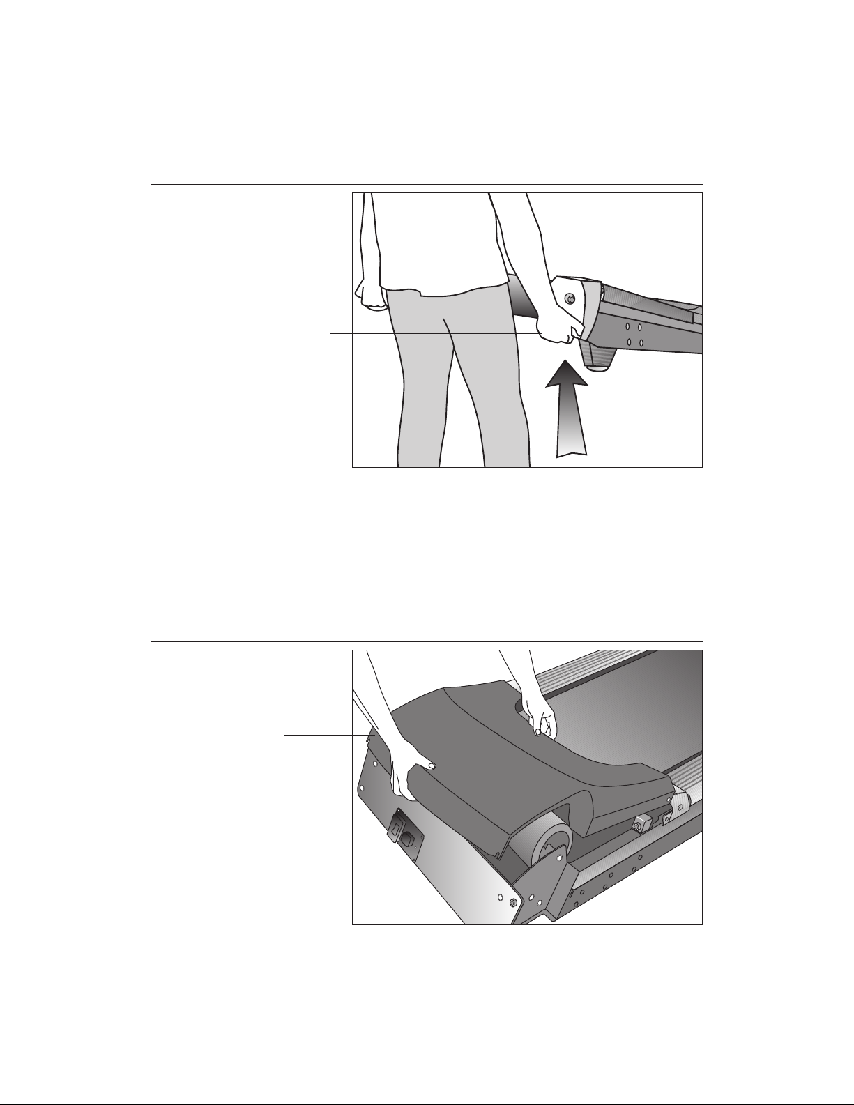
Diagram 3
Lift the rear of
the unit and roll
it to its assembly
location.
Rear end cap
Lift the unit by
grasping the
hand holds
inside the rear
end caps.
2. Make sure that the power switch is OFF. Check the ON/OFF power switch
on the front of the treadmill. Place the switch in the O (OFF) position. Make
sure that the treadmill is not plugged into a power source.
3. Move the treadmill. Diagram 3. Grasp the hand holds inside the rear end
caps and use proper lifting techniques to lift the rear end so that you can roll
the treadmill on its front wheels. To avoid injury to yourself or damage to the
unit, ask for help in maneuvering the treadmill.
Diagram 4
page 12
Remove the
hood.
Hood
4. Remove the hood. Diagram 4. Gently, lift the hood off the treadmill and set it
aside.
COMMERCIAL PRODUCTS DIVISION
Diagram 5
Remove the
shipping
fasteners from
the left side front
panel.
Shipping
fasteners found
on left and right
sides of the front
panel.
Left side
mounting bracket
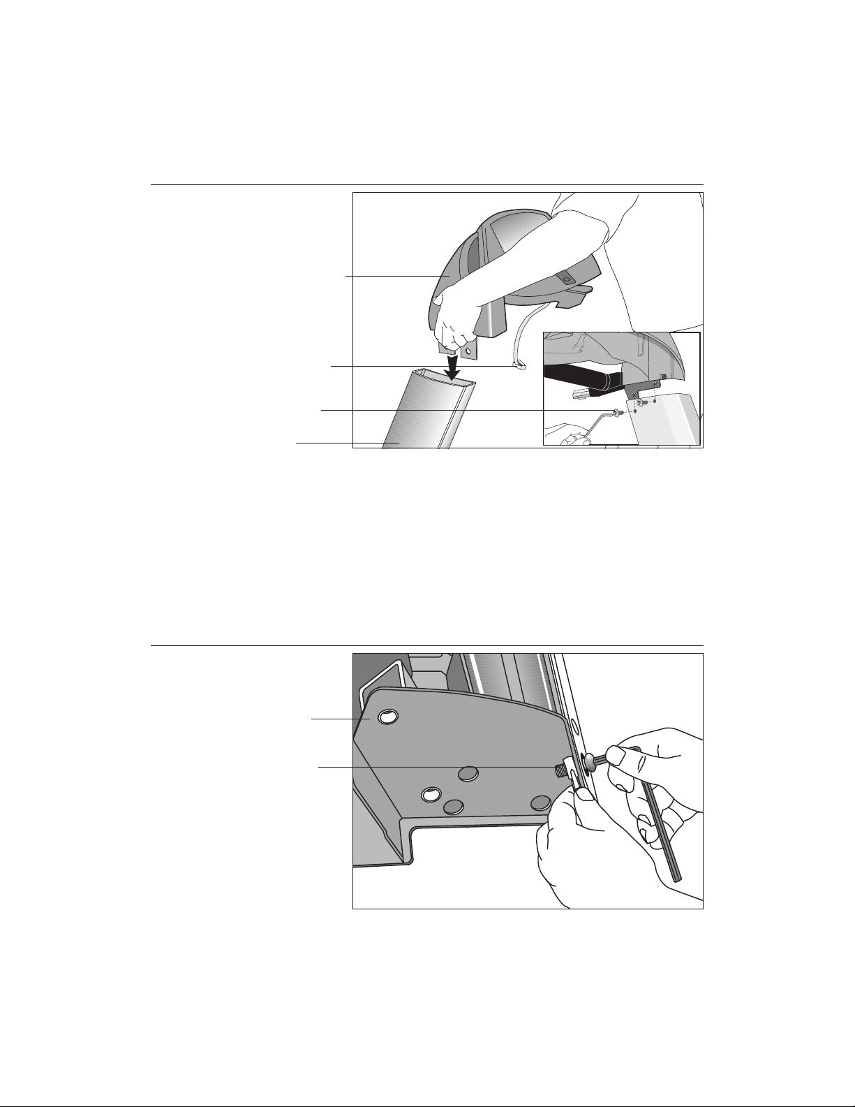
5. Attach the left side upright support. Diagram 5. Take the following steps.
a. Remove the shipping fasteners from the front panel. With the supplied
hex key and a ½-inch box end wrench, loosen and remove the two bolts
and nuts on the left side of the front panel. These fasteners hold the front
panel in place during shipping. (The front panel will drop slightly when
you remove the fasteners.) Discard the nuts, but keep the bolts.
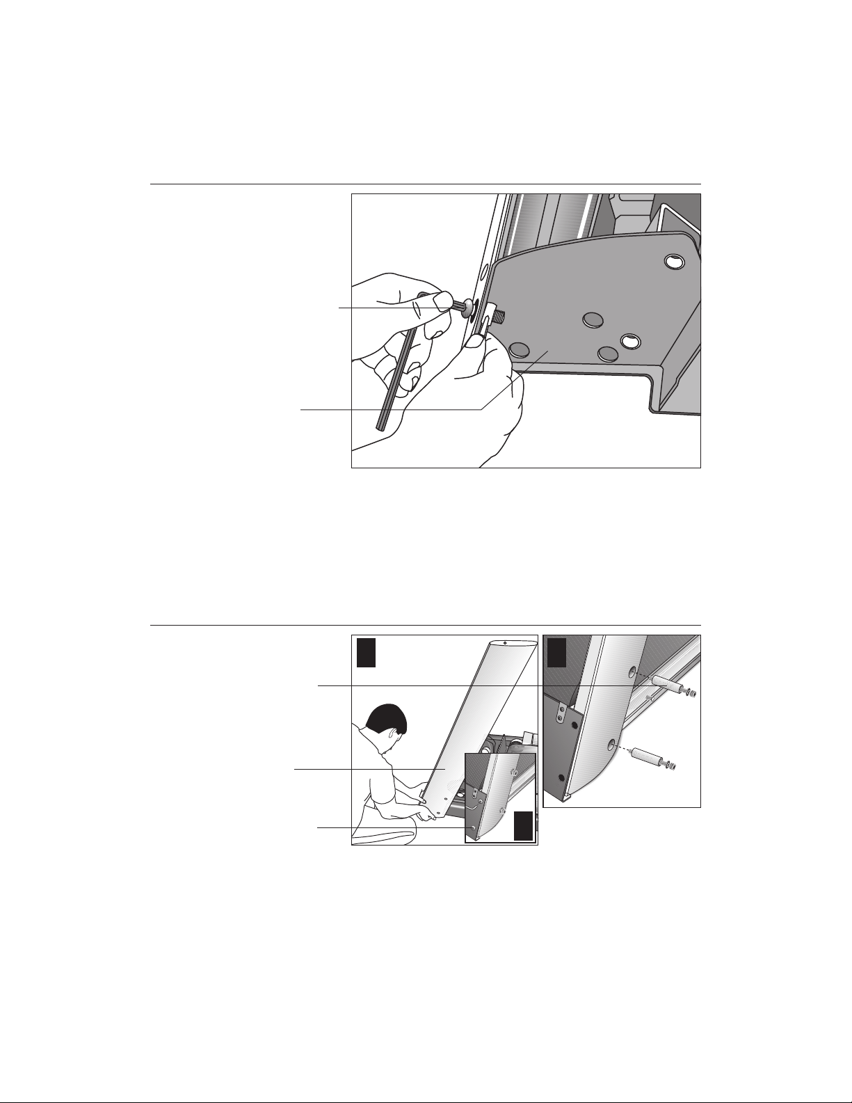
Diagram 6
Secure the left
upright support.
Screws (D),
washers (E),
and barrel
spacers (F)
Left upright
support
Shipping
fasteners with
washers (B)
1 2
3
b. Attach the left upright support by placing it inside the base mount and align-
ing the mounting holes. Obtain two long sockethead screws (D), washers (E)
and barrel spacers (F) from the Hardware kit. Place a washer and barrel
sleeve on each screw and insert the fasteners through the side of the upright
support and into the base mounts. Use the ¼-inch hex key to secure the
screws, but leave room for adjustments. See Diagram 6, #1 and #2.
c. Remove two stainless steel washers (B) from the Hardware kit and place
a washer on each of the two shipping fasteners. Reinsert the two shipping
fasteners removed in step 5a, and finger tighten. See Diagram 6, #3.
page 13
COMMERCIAL PRODUCTS DIVISION
Diagram 7
Attach the
display console
to the left upright
support.
Display console
Display cable
Screws (A) with
washers (B)
Left side upright
support
CAUTION: To avoid damage to the display cable, read the following steps
carefully. Damage to the cable due to improper assembly is not covered
by the Precor limited warranty.
6. Secure the display console to the left upright support. Diagram 7.
Remove any tape or wire ties that secure the display cable. Unwrap the
cable to remove kinks. Ask an assistant to hold the display console in place
while you attach it to the left upright support using two buttonhead screws
(A) with washer (B). Finger tighten.
Diagram 8
page 14
Remove right
side front panel
screws.
Right side
mounting bracket
Front panel
fasteners
7. Prepare to attach the right side upright. Diagram 8. Take the following steps:
a. Remove the shipping fasteners from the right front panel. Follow the same
process as in step 5a. With the supplied hex key and a ¹⁄₂-inch box end wrench,
loosen and remove the two bolts and nuts on the right side of the front panel.
COMMERCIAL PRODUCTS DIVISION
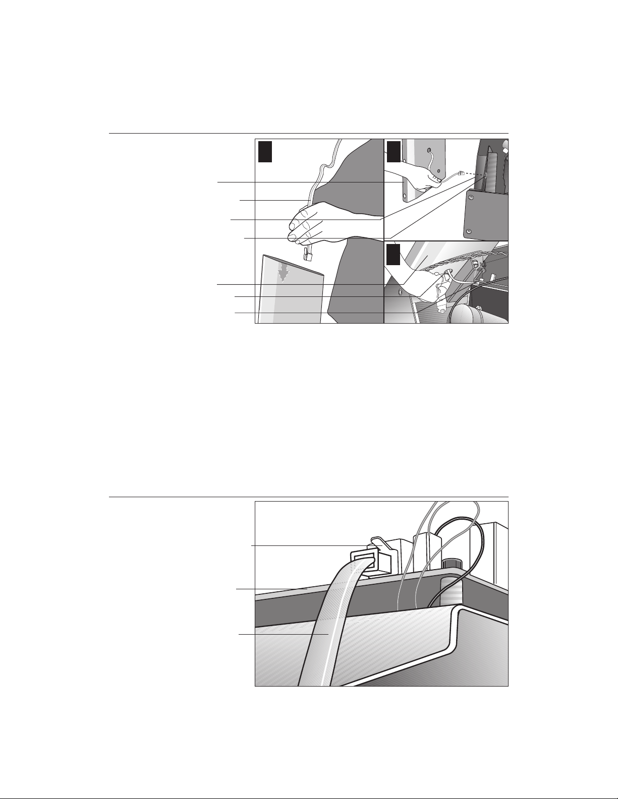
Diagram 9
Route the cable.
1
Right upright
support
Display cable
Base frame
Base mounting
bracket
Right upright
support
Bracket hole
Lower board
2
3
b. Route the display cable through the right upright support. Ask an assistant to
hold the upright support close to the right side mounting bracket. Route the
cable through the upright support (see Diagram 9, #1) and pull it out of the
large hole on the side of the support near its base. Diagram 9, #2.
Note: If you encounter difficulties with the cable, try tying a string to the
end of the cable. Attach a washer to the opposite end for weight and route
it through the upright support.
Diagram 10
c. Ask your assistant to position the right upright support inside the base mount-
ing bracket and align the mounting holes as you pull the cable through the
mounting bracket hole in the base frame. See Diagram 9, #3.
Connect the
cable.
Cable connector
Lower board
Display cable
d. Plug the cable connector into its receptacle on the lower board near the
motor. See Diagram 10. A definite “click” is heard when the cable is properly
attached. If you do not hear and feel the connector snap into place, reinsert it.
page 15
COMMERCIAL PRODUCTS DIVISION
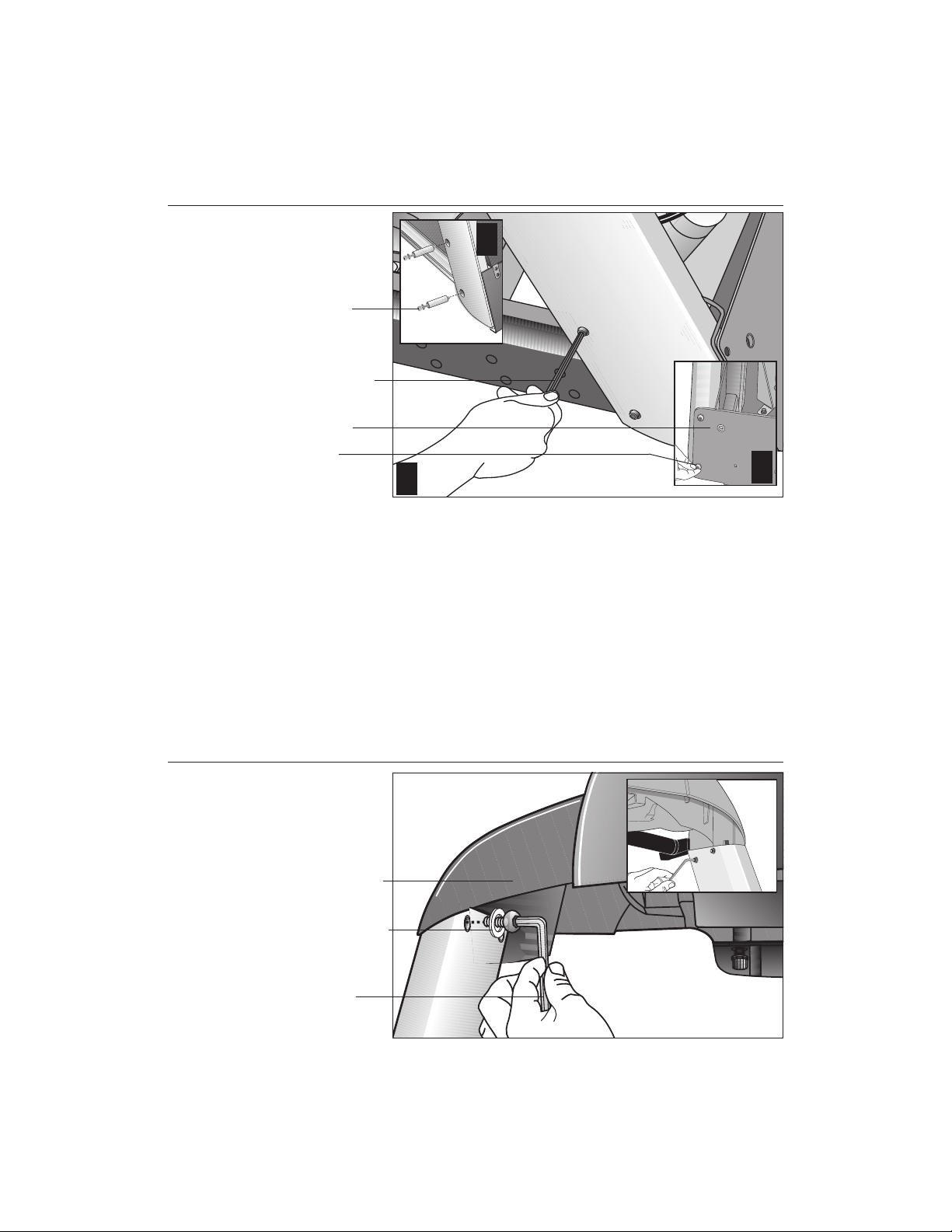
Diagram 11
Secure the right
upright support.
Screws (D),
washers (E),
and barrel
spacers (F)
Tighten so that
the upright is
secure, but
leave room for
adjustments.
Front panel
Shipping
fasteners with
washers (B)
2
1
3
8. Secure the right side upright support. Diagram 11. Obtain two long
sockethead screws (D), washers (E) and barrel spacers (F) from the Hardware
kit. Place a washer and barrel sleeve on each bolt and insert the fasteners
through the side of the upright support and into the base mounts. Diagram 11,
#1. Secure the upright support using the ¼-inch hex key. See Diagram 11, #2.
Important: Do not securely tighten the screws until after the unit has been fully
assembled. Make sure that the bolt and spacer do not pinch the cable.
Diagram 12
page 16
9. Remove two stainless steel washers (B) from the Hardware kit and place one on
each of the two bolts removed in step 7a. Reinsert the bolts and finger tighten.
Diagram 11, #3.
Secure the
display console.
Display console
1-
inch screws (A)
with washers (B)
Tighten the
screws, but
leave room for
adjustments.
10. Secure the display console to the upright supports. Diagram 12, #1. Align
the display console with the right side upright support mounts. Insert two 1-inch
screws (A) with washers (B) and finger tighten. Use the supplied hex key to
secure the screws on both upright supports, but leave room for adjustments.
See inset in Diagram 12, #2.
COMMERCIAL PRODUCTS DIVISION
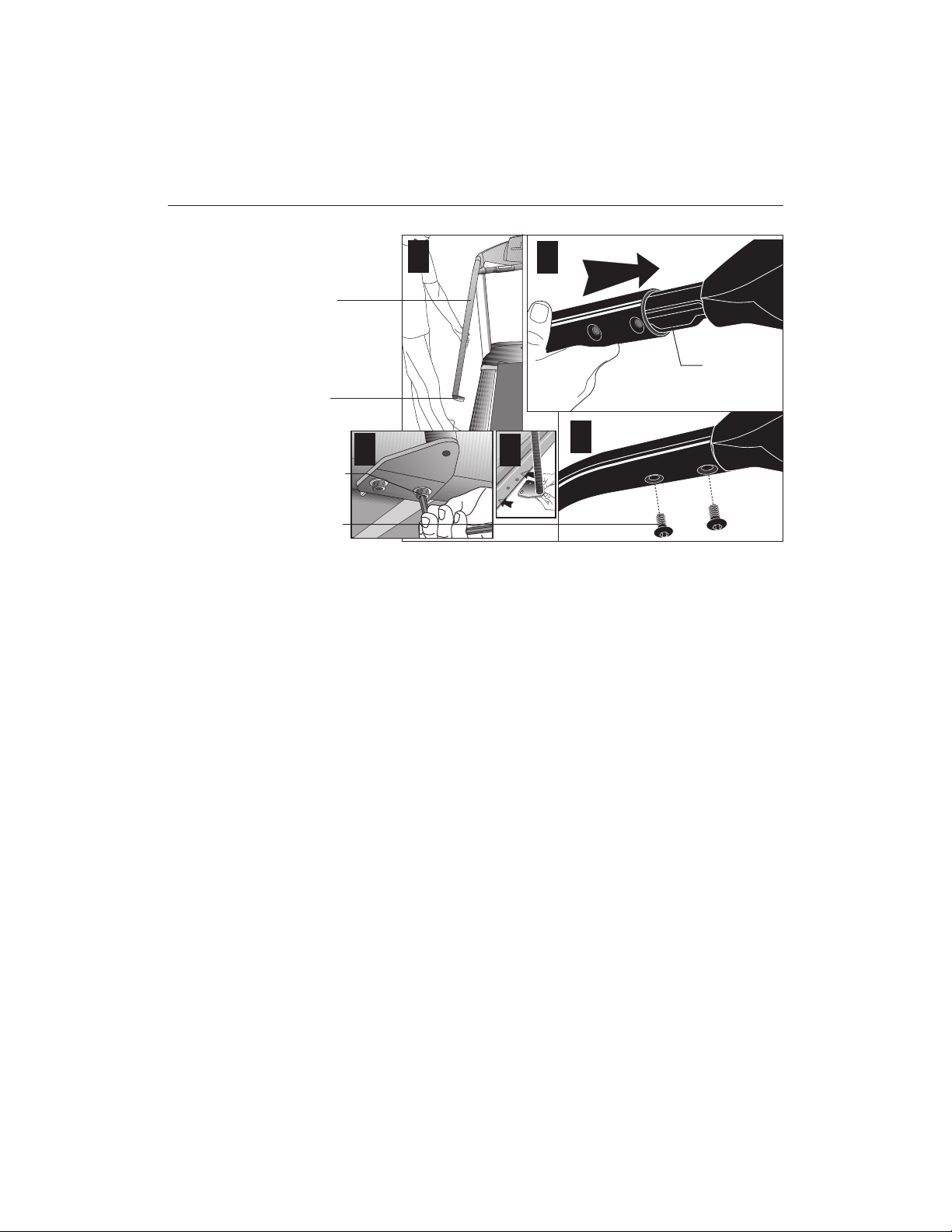
Diagram 13
Handrail alignment and installation.
Handrail
Lower
handrail
bracket
Screw (A)
and
washer (B)
Screw (C)
1
5
2
Console
extension
3
4
Important: With the handrails attached, the width of the treadmill is 36.75
inches (93 cm). It will not fit through a standard 32-inch doorway.
11. Attach the handrails. Diagram 13. For ease of assembly, place the side rails
or adjustable rear feet on blocks. Obtain assistance to lift the treadmill. Do
not place blocks beneath the running bed.
To attach the handrails, perform the following steps on
one side at a time
:
a. Position the handrail as shown in Diagram 13, #1 and #2 and slide it onto the
console extension. Insert two flat head screws (C) into the upper handrail
mounts and finger tighten. See Diagram 13, #3.
b. Align the lower handrail bracket with the two base mounts and insert two
screws (A) with washers (B). See Diagram 13, #4. Tighten the screws
with the hex key. See Diagram 13, #5.
c. Return to the upper handrail screws and securely tighten each one.
d. Perform steps a. through c. on the opposite side.
e. Obtain assistance and remove the blocks from beneath the base.
page 17
Loading...