


 Loading...
Assembling and Maintaining
Adaptive Motion Trainers®
AMT® 885 • AMT® 835

Edition Information
ASSEMBLING AND MAINTAINING ADAPTIVE MOTION TRAINERS: AMT 885 /835
P/N 300710-301 rev F
Copyright © February 2011 Precor Incorporated. All rights reserved. Specifications subject to change without notice.
Trademark Note
Precor, AMT, and EFX are registered trademarks and Preva is a trademark of Precor Incorporated. Other names in this document may be the trademarks or registered trademarks of their respective owners.
The Precor AMT is protected by one or more of the following US and foreign patents:
US 7,530,926
US 7,520,839
Other US and foreign patents pending.
Intellectual Property Notice
All rights, title, and interests in and to the software of the Preva Business Suite, the accompanying printed materials, any copies of such software, and all data collected via the Preva Business Suite, are exclusively owned by Precor or its suppliers, as the case may be.
Precor is widely recognized for its innovative, award-winning designs of exercise equipment. Precor aggressively seeks U.S. and foreign patents for both the mechanical construction and the visual aspects of its product design. Any party contemplating the use of Precor product designs is hereby forewarned that Precor considers the unauthorized appropriation of its proprietary rights to be a very serious matter. Precor will vigorously pursue all unauthorized appropriation of its proprietary rights.
Precor Incorporated
20031 142nd Ave NE, P.O. Box 7202 Woodinville, WA 98072-4002 1-800-347-4404
http://www.precor.com
Important Safety Instructions
Read the following precautions thoroughly before you begin assembly, and save them afterward for future reference.
Safety Precautions
Always follow basic safety precautions when using this equipment to reduce the chance of injury, fire, or damage. Other sections in this manual provide more details of safety features. Be sure to read these sections and observe all safety notices. These precautions include the following:
Read all instructions in this guide before installing and using the equipment and follow any labels on the equipment.
Make sure all users see a physician for a complete physical examination before they begin any fitness program.
Il est conseillé de subir un examen médical complet avant d’entreprendre tout programme d’exercise. Si vous avez des étourdissements ou des faiblesses, arrêtez les exercices immédiatement.
Do not allow children, or people unfamiliar with the operation of this equipment, on or near it. Do not leave children unsupervised around the equipment.
Make sure all users wear proper exercise clothing and shoes for their workouts and avoid loose or dangling clothing. Users should not wear shoes with heels or leather soles, and they should check the soles of their shoes to remove any dirt and embedded stones. They should also tie long hair back.
Never leave the equipment unattended when it is plugged in. Unplug the equipment from its power source when it is not in use, before cleaning it, and before providing authorized service.
Note: The optional power adapter is considered a power source for self-powered equipment.
6 |
Assembling and Maintaining Adaptive Motion Trainers: AMT 885 /835 |
Use the power adapter provided with the equipment. Plug the power adapter into an appropriate, grounded power outlet as marked on the equipment.
Care should be taken when mounting or dismounting the equipment.
Read, understand, and test the emergency stop procedures before use.
Keep the power cord or optional power adapter and plug away from heated surfaces.
Route power cables so that they are not walked on, pinched, or damaged by items placed upon or against them, including the equipment itself.
Ensure the equipment has adequate ventilation. Do not place anything on top of or over the equipment. Do not use on a cushioned surface that could block the ventilation opening.
Assemble and operate the equipment on a solid, level surface.
Proper Location for Equipment
For all equipment other than treadmills: Locate at least 40 inches (1 meter) away from walls or furniture on either side of the equipment, and 40 inches (1 meter) away from objects behind the equipment.
For treadmills: Locate at least 40 inches (1 meter) away from walls or furniture on either side of the treadmill, and at least 80 inches (2 meters) away from objects behind the treadmill.
Important: These location standards should also be used when positioning equipment away from sources of heat, such as radiators, heat registers, and stoves. Avoid temperature extremes.
Keep equipment away from water and moisture. Avoid dropping anything on or spilling anything inside the equipment to prevent electric shock or damage to the electronics.
Do not operate electrically powered equipment in damp or wet locations.
Never operate this equipment if it has a damaged cord or plug, if it is not working properly, or if it has been dropped, damaged, or exposed to water. Call for service immediately if any of these conditions exist.
Important Safety Instructions |
7 |
Maintain the equipment to keep it in good working condition, as described in the Maintenance section of the assembly and maintenance guide. Inspect the equipment for incorrect, worn, or loose components, and then correct, replace or tighten prior to use.
If you plan to move the equipment, obtain help and use proper lifting techniques. refer to the "Moving the Equipment" section of the assembly and maintenance guide.
Use the equipment only for its intended purpose as described in this manual. Do not use accessory attachments that are not recommended by Precor. Such attachments may cause injuries.
Do not operate the equipment where aerosol (spray) products are being used or where oxygen is being administered.
Do not use outdoors.
Do not attempt to service the equipment yourself, except to follow the maintenance instructions in this manual.
Never drop or insert objects into any opening. Keep hands away from moving parts.
Do not set anything on the stationary handrails, handlebars, control console, or covers. Place liquids, magazines, and books in the appropriate receptacles.
Do not lean on or pull on the console at any time.
CAUTION: DO NOT remove the cover, or you may risk injury due to electric shock. Read the assembly and maintenance guide before operating. There are no user-serviceable parts inside. Contact Customer Support if the equipment needs servicing. For use with single phase AC supply only.
8 |
Assembling and Maintaining Adaptive Motion Trainers: AMT 885 /835 |
Educating Users
Take time to educate users about the Important Safety Instructions found in both the User Reference Manual and Product Owner’s Manual. Explain to your club or facility patrons that they should observe the following precautions:
Hold onto a stationary handrail or handlebar while assuming the starting position on the equipment.
Face the console at all times.
Hold on to a stationary handrail or handlebar with one hand whenever you operate the console keys with the other hand.
Hazardous Materials and Proper Disposal
The batteries within self-powered equipment contain materials that are considered hazardous to the environment. Federal law requires proper disposal of these batteries.
If you plan to dispose of your equipment, contact Precor Commercial Products Customer Support for information regarding battery removal. Refer to Obtaining Service.
Product Recycling and Disposal
This equipment must be recycled or discarded according to applicable local and national regulations.
Product labels, in accordance with European Directive 2002/96/EC concerning waste electrical and electronic equipment (WEEE), determine the framework for the return and recycling of used equipment as applicable throughout the European Union. The WEEE label indicates that the product is not to be thrown away, but rather reclaimed upon end of life per this Directive.
In accordance with the European WEEE Directive, electrical and electronic equipment (EEE) is to be collected separately and to be reused, recycled, or recovered at end of life. Users of EEE with the WEEE label per Annex IV of the WEEE Directive must not dispose of end of life EEE as unsorted municipal waste, but use the collection framework available to customers for the return, recycling, and recovery of WEEE. Customer participation is important to minimize any potential effects of EEE on the environment and human health due to the potential presence of hazardous substances in EEE. For proper collection and treatment, refer to Obtaining Service.
Important Safety Instructions |
9 |
Regulatory Notices for the RFID Module
When equipped with a control console as described in this document, this equipment may include a radio-frequency identification (RFID) module. The RFID module has been certified to operate at temperatures between -20ºC and 85°C (-4°F and 185°F).
Radio Frequency Interference (RFI)
The RFID module conforms to the following national standards defining acceptable limits for radio frequency interference (RFI).
Federal Communications Commission, Part 15
This equipment has been tested and found to comply with the limits for a Class A digital device, pursuant to Part 15 of the FCC Rules. These limits are designed to provide reasonable protection against harmful interference in a commercial installation. The equipment generates, uses, and can radiate radio frequency energy and, if not installed and used in accordance with the owner’s manual instructions, can cause harmful interference to radio communications.
Operation is subject to the following two conditions: (1) this device may not cause harmful interference, and (2) this device must accept any interference received, including interference that may cause undesired operation.
WARNING Per FCC rules, changes or modifications not expressly approved by the manufacturer could
void the user’s authority to operate the equipment.
10 |
Assembling and Maintaining Adaptive Motion Trainers: AMT 885 /835 |
Industry Canada
This device complies with RSS-210:2007 of the Spectrum Management & Telecommunications Radio Standards Specification. Operation is subject to the following two conditions: (1) this device may not cause harmful interference, and (2) this device must accept any interference received, including interference that may cause undesired operation.
This Class A digital apparatus complies with Canadian ICES-003.
Cet appareil numérique de la classe A est conforme à la norme NMB-003 du Canada.
ATTENTION: Haute Tension Débranchez avant de réparer
European Applications
CE compliance is claimed to the following directives:
1999/5/EC R&TTE Directive
2006/95/EC LVD Directive
2002/95/EC RoHS Directive
Directive compliance has been verified to the following standards:
EN 55022
EN 300 330-1 V1.5.1
EN 300 330-2 V1.3.1
EN 301 489-3 V1.4.1
EN 301 489-1 V1.8.1
EN 60950-1
Important Safety Instructions |
11 |
Regulatory Notices for Cardiovascular Exercise Equipment
The regulatory information in this section applies to the exercise equipment and its control console.
Safety Approvals for Cardiovascular Equipment
Precor equipment has been tested and found to comply with the following applicable safety standards.
Cardiovascular Type Equipment:
CAN/CSA, IEC, EN 60335-1 (Household and similar electrical appliances - Safety)
EN 957 (Stationary training equipment, class S/B compliant equipment)
PVS and P80 Regulatory Notice
This Precor equipment has been tested and found to comply with the following applicable safety standards.
CAN/CSA, UL, IEC, EN 60065 (Audio, video and similar electronic apparatus - Safety)
Radio Frequency Interference (RFI)
This Precor exercise equipment conforms to the following national standards defining acceptable limits for radio frequency interference (RFI).
Federal Communications Commission, Part 15
This equipment has been tested and found to comply with the limits for a Class A digital device, pursuant to Part 15 of the FCC Rules. These limits are designed to provide reasonable protection against harmful interference in a commercial installation. The equipment generates, uses, and can radiate radio frequency energy and, if not installed and used in accordance with the owner’s manual instructions, may cause harmful interference to radio communications.
WARNING Per FCC rules, changes or modifications not expressly approved by Precor could void the
user’s authority to operate the equipment.
12 |
Assembling and Maintaining Adaptive Motion Trainers: AMT 885 /835 |
Industry Canada
This Class A digital apparatus complies with Canadian ICES-003.
Cet appareil numérique de la classe A est conforme à la norme NMB-003 du Canada.
ATTENTION: Haute Tension Débranchez avant de réparer
European Applications
CE compliance is claimed to the following directives:
2004/108/EC EMC Directive
2006/95/EC LVD Directive
2002/95/EC RoHS Directive
Directive compliance has been verified to the following standards:
EN 55022
EN 55024
EN 60335-1
EN 60065 (P80 and PVS)
Important Safety Instructions |
13 |
Electrical Recommendations: All Equipment Excluding Treadmills
Note: This is a recommendation only. NEC (National Electric Code) guidelines or local region electric codes must be followed.
For equipment fitted with a P80 console or Personal Viewing System (PVS) screen a separate power connection is required. For a 20 amp branch circuit up to 10 screens can be connected. If the branch circuit has any other devices plugged into the circuit the number of screens must be reduced by the wattage of the other devices.
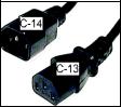
Note: The typical splitter power cords that have IEC-320 C13 and C14 plugs have a recommended maximum capacity of five screens.
Figure 1: IEC-320 C13 and C14 plugs
Obtaining Service
Do not attempt to service the equipment except for maintenance tasks. If any items are missing, contact your dealer. For more information regarding customer support numbers or a list of Precor authorized service centers, visit the Precor web site at http://www.precor.com.
Obtaining Updated Documentation
Current documentation for Experience Series consoles and Preva Networked Fitness software is available at http://www.precor.com/productmanuals. You may want to check in for updated information from time to time as the universe of Preva features expands.
Table of Contents |
|
Important Safety Instructions................................................... |
5 |
Safety Precautions ................................................................................ |
5 |
Educating Users..................................................................................... |
8 |
Hazardous Materials and Proper Disposal .................................... |
8 |
Product Recycling and Disposal........................................................ |
8 |
Regulatory Notices for the RFID Module........................................ |
9 |
Regulatory Notices for Cardiovascular |
|
Exercise Equipment...................................................................... |
11 |
Electrical Recommendations: All Equipment |
|
Excluding Treadmills .................................................................. |
13 |
Obtaining Service................................................................................ |
13 |
Obtaining Updated Documentation............................................... |
13 |
Assembling the AMT................................................................ |
17 |
Hardware Kit (not to scale).............................................................. |
18 |
Required Tools ..................................................................................... |
19 |
Performing the Assembly ................................................................. |
19 |
Removing Access Covers.................................................................. |
22 |
Threading the Cables ......................................................................... |
22 |
Replacing Access Covers................................................................. |
24 |
Leveling the AMT............................................................................... |
24 |
Breaking in the Equipment............................................................... |
26 |
Installing the Console.............................................................. |
27 |
Threading the Cable Assembly (P80)........................................... |
27 |
Connecting Cables (P80) ................................................................ |
29 |
Completing the Console Installation (P80)................................. |
33 |
Threading the Cable Assembly (P30)........................................... |
33 |
Connecting Cables (P30) ................................................................. |
35 |
Completing the Console Installation (P30)................................ |
36 |
Verifying That the Heart Rate Display Is Operational ............. |
36 |
Important Safety Instructions |
15 |
Maintenance ............................................................................ |
37 |
Daily Cleaning...................................................................................... |
37 |
Daily Inspection................................................................................... |
38 |
Weekly Maintenance......................................................................... |
39 |
Monthly Maintenance....................................................................... |
39 |
Storing the Chest Strap.................................................................... |
40 |
Moving the Equipment..................................................................... |
40 |
Long-Term Storage ........................................................................... |
40 |
Self-Powered Features ............................................................ |
41 |
Informational Displays Prior to Shutdown................................... |
42 |
Symptoms of a Low Battery............................................................. |
42 |
Using the Optional Power Adapter................................................ |
42 |
The Optional Power Adapter Kit .................................................... |
43 |
Replacing the Battery......................................................................... |
43 |
Commercial Cardiovascular Equipment Limited Warranty .... |
45 |
Chapter 1
Assembling the AMT
Important: The instructions in the following procedures are described from the perspective of a person standing directly in front of the equipment (that is, on the opposite side of the control console from a person using the equipment). These descriptions may not match the names of certain parts in the parts list, because such parts are named relative to the back of the equipment.
To prepare the AMT for assembly:
Open the box and assemble the components in the sequence presented in this guide.
Assemble and operate your equipment on a hard, level surface in the area intended for use.
Important: Do not grasp any plastic parts of the unit while lifting or moving the unit. The plastic parts are non-structural covers and are not capable of supporting the weight of the unit.
Provide ample space around the unit.
Assemble the equipment according to the guidelines in this manual to ensure you do not void the Precor Limited Warranty.
Important: Any damage caused during installation is not covered by the Precor Limited Warranty.
Attach all fasteners and partially tighten them. Do not fully tighten fasteners until instructed to do so.
WARNING You will need assistance to assemble this unit.
DO NOT attempt assembly by yourself.
18 |
Assembling and Maintaining Adaptive Motion Trainers: AMT 885 /835 |
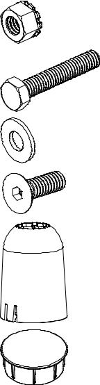
Hardware Kit (not to scale)
The hardware kit shipped with this equipment contains the fasteners and other hardware components shown in the following table. Before you begin assembly, make sure that your hardware kit is complete. If not, please contact Precor Customer Support.
Fasteners |
Quantity |
Locknuts ( -inch) |
8 |
Hex head screws |
4 |
( -inch x 1³-inch) |
|
Flat washers ( -inch) |
8 |
Flat head hex drive screws |
4 |
(¹-inch x ³-inch) |
|
Plastic boots |
2 |
End caps |
2 |
Assembling the AMT |
19 |
Required Tools
-inch hex wrench
-inch hex wrench
#2 Phillips screwdriver
Rubber mallet
SAE standard socket set
Wire cutter
Torque wrench (calibrated in inch-pounds)
Performing the Assembly
DANGER Do not attempt to connect electrical power until all assembly procedures are complete and the console
is properly installed.
Follow these steps to assemble the AMT base unit.
To begin assembly:
1.Remove the two side fasteners that hold the front frame tube to the shipping pallet and cut the tie wraps that secure the rear base.
CAUTION: Do not move the AMT off its shipping pallet without assistance. To avoid unnecessary movement of the foot plates, do not install the handlebars until you begin the next procedure.
2.Lift the rear base and roll the AMT forward while your assistant stabilizes the front base and guides it off the shipping pallet onto the floor.
Note: Begin assembly in the area intended for use.

20 |
Assembling and Maintaining Adaptive Motion Trainers: AMT 885 /835 |
3.Insert the end caps into the front frame tube. If necessary, use a rubber mallet to tap them into place.
Figure 2: Removal of unit from pallet and insertion of end caps
To attach the handlebars:
1.Slide a plastic boot onto each handlebar.
Figure 3: Boot attachment
2.Use the following graphic to determine the proper position of the handlebars.
Assembling the AMT |
21 |
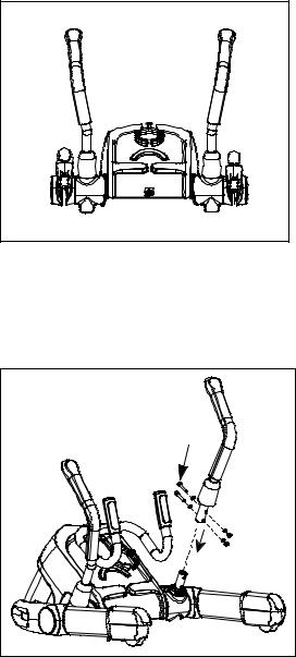
Note: When the handlebars are mounted correctly, each bends slightly outward.
Figure 4: View of handlebar placement
3.Attach the handlebars using four -inch x 1¾-inch hex head screws, eight -inch washers, and four -inch locknuts. Using a torque wrench, tighten the fasteners with 180 to 200 inch-pounds of torque.
Figure 5: Handlebar attachment
4.Rotate the plastic boot so that its tab aligns with the cutout below it, and then press the boot downward to secure it in place.
22 |
Assembling and Maintaining Adaptive Motion Trainers: AMT 885 /835 |
Removing Access Covers
With its access covers removed, the AMT provides easy access to its cables and internal components.
Tip: In the following procedure, set aside the covers and their mounting hardware in groups, in the order in which you remove them. This simplifies reinstallation later.
To remove the access covers:
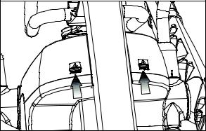
1.Using a rubber mallet or the heel of your hand, tap at an upward angle against the side of the top column cover to snap it loose.
Figure 6: Where to place pressure when removing top cover
2.Lift the cover, then slide it toward the rear of the equipment and out.
3.Using a ” hex wrench, disconnect the two 1-inch buttonhead screws at the bottom of the front cover, then snap the cover loose.
Threading the Cables
Depending on the model of console you are installing and the options it includes, you will need to install one or more of the following cables:
Television (coaxial with F connectors)
Power
Ethernet
Precor recommends threading new cables from the top down, to take advantage of gravity. A fish tape (a thin metal strip with a hook or clasp on one end, available from professional hardware vendors) can be helpful during this procedure.
Assembling the AMT |
23 |
To thread new cables through the equipment:
1.Select the console power cable (red and black, individual leads), the Ethernet cable (flat and black), or the television cable (round and black).
2.Thread the cable through the center column at the front of the equipment.
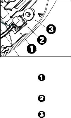
3.Guide the end of the cable through the gap at the bottom of the center column, then attach it to the appropriate connector on the jack panel. Refer to the following illustration and table for the position of each connector.
Connect … |
To … |
The console power |
The power cable assembly |
cable |
|
The Ethernet cable |
The eight-connector modular jack on the |
|
jack panel |
The television cable |
The coaxial connector on the jack panel |
4.Repeat steps 1 through 3 until all three cables are completely installed.
5.Insert all cables into the cable clips on the center frame pillar just below the bottom of the center column. Use plastic ties to bind the cables together below the clips and to route them away from any moving parts.
24 |
Assembling and Maintaining Adaptive Motion Trainers: AMT 885 /835 |
Replacing Access Covers
After you install the console cables, you can return the access covers to their previous positions on the equipment.
To replace the access covers:
1.Snap the front cover back into place. Reinsert the two buttonhead screws you removed with the front cover, then tighten them using a ” hex wrench.
2.Position the top column cover between the handlebars and the body of the AMT. Make sure that the sides of the top column cover extend over the upper edges of the body covers, then use the heel of your hand or a rubber mallet to tap the cover back into place.
Leveling the AMT
It is important that you level and stabilize the AMT properly every time you move it.
CAUTION: To eliminate movement, make sure the adjustable feet are in contact with the floor. Also, make sure that the unit sits on a flat surface. Adjusting the feet of the unit cannot compensate for extremely uneven surfaces.
To level the AMT:
1.Gently rock the AMT while standing on one of its foot plates and grabbing the opposite handlebar. First stand on the left foot plate and grab the right handlebar to rock the AMT, then repeat the step while standing on the right foot plate and holding the left handlebar. If there is any movement, ask your assistant to tip the unit on its side while you locate the adjustable feet.
Assembling the AMT |
25 |
2. Reposition the adjustable feet as needed.
If you want to … |
Then turn the adjustable feet … |
|||||||||||||
Raise the front end of the AMT |
Counterclockwise |
|||||||||||||
Lower the front end of the AMT |
Clockwise |
|||||||||||||
|
|
|
|
|
|
|
|
|
|
|
|
|
|
|
|
|
|
|
|
|
|
|
|
|
|
|
|
|
|
|
|
|
|
|
|
|
|
|
|
|
|
|
|
|
|
|
|
|
|
|
|
|
|
|
|
|
|
|
|
|
|
|
|
|
|
|
|
|
|
|
|
|
|
|
|
|
|
|
|
|
|
|
|
|
|
|
|
|
|
|
|
|
|
|
|
|
|
|
|
|
|
|
|
|
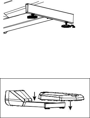
Figure 7: Location of adjustable feet
3.When you are finished positioning the adjustable feet, place the unit on the floor. Try rocking it again, as described in step 1, to verify that it is level.
4.To install the rear pedestal, align it over the rear crosspiece and press it gently into place.
Figure 8: Rear pedestal placement
26 |
Assembling and Maintaining Adaptive Motion Trainers: AMT 885 /835 |
Breaking in the Equipment
Precor equipment does not require an actual break-in period. However, moving components such as belts, gears, and bearings can settle while the equipment is being stored or shipped. This can cause the equipment to operate with a small amount of roughness or noise when it starts up for the first time.
The equipment usually returns to smooth operation after a day or two of normal use. If it does not, contact your dealer for assistance. For more information, refer to Obtaining Service.
Chapter 2
Installing the Console
To make installation easier, all Precor Experience Series consoles use the same mounting hardware and connector locations whenever possible. The installation sequence for any of them is as follows:
Threading the cable assembly
Connecting cables
Completing the installation (tightening the mounting screws and attaching the back cover)
The following sections describe how to perform these tasks.
Threading the Cable Assembly (P80)
Earlier in the installation, you threaded the necessary cables through the frame of the base unit and out the passthrough opening in the console mount. As you line up the back plate on the console with the console mount, you must make sure that the cable assembly passes correctly through the openings in both components.
28 |
Assembling and Maintaining Adaptive Motion Trainers: AMT 885 /835 |
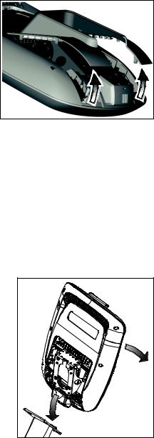
Important: Before you begin the following procedure, remove the rear cover from the control console. To remove the cover, use your fingernails to pry the lower edge loose, then swing the cover up and out as shown in the following illustration.
Figure 9: Removing the access cover from the P80 console
To thread the cable assembly:
1.Make sure that as much of each cable as possible passes through the opening in the middle of the console mount on the base unit.
2.Position the console over the console mount.
3.Rest the console on the console mount so that the notch on the bottom of the console’s back plate rests on the rectangular hook at the bottom of the console mount, as shown in the following figure.
Figure 10: Console positioning on base unit
4.Tilt the console forward until it stops. Use one hand to steady the console in this position, or ask your assistant to do so.
Loading...