


Operator Manual
Manuel de l’opérateur
Manual del operador
|
PM0645500 |
ELECTRIC GENERATOR - GROUPE ELECTROGENE - GENERADOR ELECTRICO |
|
|
|
|
|
IMPORTANT – Please make certain that persons who are to use this equipment thoroughly read and understand these instructions and any additional instructions provided prior to operation.
IMPORTANT - Prière de vous assurer que les personnes destinées à utiliser cet appareil ont pris soin d'en lire et d'en comprendre le mode d'emploi ou les directives avant de le mettre en marche.
IMPORTANTE - Asegúrese que las personas que utilizarán este equipo lean y entiendan completamente estas instrucciones y cualquier instrucción adicional proporcionada antes del funcionamiento.
|
www.powermate.com |
|
|
04/06 0063805 |
|


Thank you for selecting a Coleman® Powermate® Generator. The Coleman® Powermate® generator has been made to supply reliable, portable electrical power when utility power is not available. We hope you will enjoy your new generator. Welcome to our worldwide family of Coleman® Powermate® generator users.
Merci d'avoir choisi le groupe électrogène Coleman® Powermate®. Ce groupe électrogène Coleman® Powermate® a été conçu pour fournir le pouvoir électrique, portatif et fiable quand le pouvoir d'utilité n'est pas disponible. Nous espérons que votre groupe électrogène vous donnera entière satisfaction. Bienvenue dans la famille mondiale des utilisateurs de groupes électrogènes Coleman® Powermate®.
Gracias por seleccionar un generador Coleman® Powermate®. El generador Coleman® Powermate® ha sido diseñado para proporcionar energía eléctrica confiable y portátil cuando no hay servicio disponible de energía pública.
Esperamos que disfrute de su nuevo generador. Bienvenido a nuestra familia de usuarios de generadores Coleman® Powermate® a nivel mundial.
STOP |
ARRÊT |
ALTO |
|
DO NOT RETURN TO STORE! |
NE PAS RETOURNER AU MAGASIN! |
NO LO DEVUELVA A LA TIENDA! |
|
CALL US FIRST! |
APPELEZ–NOUS D’ABORD! |
¡PRIMERO LLÁMENOS! |
|
CUSTOMER HOTLINE |
ASSISTANCE TELEPHONIQUE |
LÍNEA DIRECTA DE ATENCIÓN |
|
1-800-445-1805 |
|||
A LA CLIENTELE |
AL CLIENTE |
||
or 1-308-237-2181 |
|||
1-800-445-1805 |
1-800-445-1805 |
||
FOR QUESTIONS OR |
|||
ou 1-308-237-2181 |
o 1-308-237-2181 |
||
SERVICE INFORMATION |
|||
POUR L'INFORMATION DE |
PARA la INFORMACION de |
||
|
|||
|
QUESTIONS OU SERVICE |
PREGUNTAS O SERVICIO |
|
|
|
|
www.powermate.com |
|
3 |
|
Customer Hotline 1-800-445-1805 |
|
|
|
|
|

TABLE OF CONTENTS
Safety and operation rules . . . . . . . . . . . . . . . . . . . . . . 5 Spark arresting muffler . . . . . . . . . . . . . . . . . . . . . . . . . 6 Determining total wattage. . . . . . . . . . . . . . . . . . . . . . . 6 Operating voltage . . . . . . . . . . . . . . . . . . . . . . . . . . . . . 7 Installation. . . . . . . . . . . . . . . . . . . . . . . . . . . . . . . . . . . 7 Before operation . . . . . . . . . . . . . . . . . . . . . . . . . . . . . . 8
Grounding the generator . . . . . . . . . . . . . . . . . . . . 8 Lubrication . . . . . . . . . . . . . . . . . . . . . . . . . . . . . . . 8 Low oil sensor . . . . . . . . . . . . . . . . . . . . . . . . . . . . 8 Fuel . . . . . . . . . . . . . . . . . . . . . . . . . . . . . . . . . . . . 8 Cord-set wiring . . . . . . . . . . . . . . . . . . . . . . . . . . . . . . . 8 Major generator features . . . . . . . . . . . . . . . . . . . . . . . 9 Starting the unit. . . . . . . . . . . . . . . . . . . . . . . . . . . . . . 10 Pre-start preparation . . . . . . . . . . . . . . . . . . . . . . 10 Starting the engine . . . . . . . . . . . . . . . . . . . . . . . . 10 Applying load . . . . . . . . . . . . . . . . . . . . . . . . . . . . 10 Shutting the generator off . . . . . . . . . . . . . . . . . . 10
Break-in procedure. . . . . . . . . . . . . . . . . . . . . . . . 11 Maintenance . . . . . . . . . . . . . . . . . . . . . . . . . . . . . . . . 11 Brushes . . . . . . . . . . . . . . . . . . . . . . . . . . . . . . . . 11 Inspecting the brushes . . . . . . . . . . . . . . . . . . . . . 11 Exciting the generator . . . . . . . . . . . . . . . . . . . . . 11 Heat shield . . . . . . . . . . . . . . . . . . . . . . . . . . . . . . 11 Engine carburetor icing . . . . . . . . . . . . . . . . . . . . 11 Quick starting tips. . . . . . . . . . . . . . . . . . . . . . . . . 11 Service and storage . . . . . . . . . . . . . . . . . . . . . . . . . . 12 Infrequent service. . . . . . . . . . . . . . . . . . . . . . . . . 12 Long term storage . . . . . . . . . . . . . . . . . . . . . . . . 12 Service information. . . . . . . . . . . . . . . . . . . . . . . . . . . 12 Limited warranty . . . . . . . . . . . . . . . . . . . . . . . . . . . . . 13 Parts drawing . . . . . . . . . . . . . . . . . . . . . . . . . . . . . . . 32 Parts list. . . . . . . . . . . . . . . . . . . . . . . . . . . . . . . . . 33-34 Maintenance record . . . . . . . . . . . . . . . . . . . . . . . . . . 35
TABLE DES MATIERES
Régles d’opération et de sécurité. . . . . . . . . . . . . . . . 14 Silencieux pare-étincelles. . . . . . . . . . . . . . . . . . . . . . 15 Determination de la puissance totale nécessaire. . . . 15 Vérifier la tension . . . . . . . . . . . . . . . . . . . . . . . . . . . . 16 Installation. . . . . . . . . . . . . . . . . . . . . . . . . . . . . . . . . . 16 Avant de mettre en marche . . . . . . . . . . . . . . . . . . . . 17
Mise en place de l'appareil . . . . . . . . . . . . . . . . . . 17 Lubrification . . . . . . . . . . . . . . . . . . . . . . . . . . . . . . 17 Le détecteur de bas niveau d'huile . . . . . . . . . . . 17 Carburant. . . . . . . . . . . . . . . . . . . . . . . . . . . . . . . . 17 Câble d'installation de l'appareil . . . . . . . . . . . . . . . . . 17 Caractéristiques principales du groupe electrogene . 18 Démarrage de l'appareil . . . . . . . . . . . . . . . . . . . . . . . 19 Préparatifs au démarrage . . . . . . . . . . . . . . . . . . . 19 Démarrage du moteur . . . . . . . . . . . . . . . . . . . . . . 19 Branchement des appareils. . . . . . . . . . . . . . . . . . 19 Arrêt de l'appareil . . . . . . . . . . . . . . . . . . . . . . . . . 20
Rodage . . . . . . . . . . . . . . . . . . . . . . . . . . . . . . . . . 20 Entretien . . . . . . . . . . . . . . . . . . . . . . . . . . . . . . . . . . . 20 Les balais . . . . . . . . . . . . . . . . . . . . . . . . . . . . . . . 20 Inspection des balais. . . . . . . . . . . . . . . . . . . . . . . 20 Excitation de l'appareil. . . . . . . . . . . . . . . . . . . . . . 20 Écrans de chaleur . . . . . . . . . . . . . . . . . . . . . . . . . 20 Givrage du carburateur . . . . . . . . . . . . . . . . . . . . . 20 Trucs de démarrage rapide . . . . . . . . . . . . . . . . . . 21 Usage et entreposage . . . . . . . . . . . . . . . . . . . . . . . . 21 Usage peu fréquent. . . . . . . . . . . . . . . . . . . . . . . . 21 Entreposage à long terme. . . . . . . . . . . . . . . . . . . 21 Service clientèle . . . . . . . . . . . . . . . . . . . . . . . . . . . . . 21 Garantie limitée . . . . . . . . . . . . . . . . . . . . . . . . . . . . . 22 Schema des pièces . . . . . . . . . . . . . . . . . . . . . . . . . . 32 Liste des pièces. . . . . . . . . . . . . . . . . . . . . . . . . . . 33-34 Rapport d'entretien . . . . . . . . . . . . . . . . . . . . . . . . . . . 35
INDICE
Reglas de seguridad y de funcionamiento . . . . . . . . . 23 Silenciador apagachispas. . . . . . . . . . . . . . . . . . . . . . 24 Como determinar el vataje total . . . . . . . . . . . . . . . . . 24 Requerimiento de voltaje . . . . . . . . . . . . . . . . . . . . . . 25 Instalacion. . . . . . . . . . . . . . . . . . . . . . . . . . . . . . . . . . 25 Antes de la operacion. . . . . . . . . . . . . . . . . . . . . . . . . 26
Puesta a tierra del generador . . . . . . . . . . . . . . . . 26 Lubricacion . . . . . . . . . . . . . . . . . . . . . . . . . . . . . . 26 El sensor del nivel bajo de aceite . . . . . . . . . . . . . 26 Combustible. . . . . . . . . . . . . . . . . . . . . . . . . . . . . . 26 Alambrado del juego de cordones . . . . . . . . . . . . . . . 26 Caracteristicas principales del generador . . . . . . . . . 27 Arranque de la unidad . . . . . . . . . . . . . . . . . . . . . . . . 28 Preparacion antes de arrancar . . . . . . . . . . . . . . . 28 Arranque del motor . . . . . . . . . . . . . . . . . . . . . . . . 28 Como aplicar una carga . . . . . . . . . . . . . . . . . . . . 28 Apagado del generador. . . . . . . . . . . . . . . . . . . . . 29
Procedimiento de arranque inicial. . . . . . . . . . . . . 29 Mantenimiento . . . . . . . . . . . . . . . . . . . . . . . . . . . . . . 29 Escobillas . . . . . . . . . . . . . . . . . . . . . . . . . . . . . . . 29 Revisión de las escobillas . . . . . . . . . . . . . . . . . . . 29 Excitacion del generador. . . . . . . . . . . . . . . . . . . . 29 Escudo contra el calor. . . . . . . . . . . . . . . . . . . . . . 29 Congelamiento del carburador del motor . . . . . . . 29 Instrucciones rápidas para el arranque. . . . . . . . . 30 Servicio y almacenamiento. . . . . . . . . . . . . . . . . . . . . 30 Servicio poco frecuente. . . . . . . . . . . . . . . . . . . . . 30 Almacenamiento a largo plazo . . . . . . . . . . . . . . . 30 Informacion de servicio al cliente . . . . . . . . . . . . . . . . 30 Garantia limitada. . . . . . . . . . . . . . . . . . . . . . . . . . . . . 31 Diagrama de piezas . . . . . . . . . . . . . . . . . . . . . . . . . . 32 Lista de piezas . . . . . . . . . . . . . . . . . . . . . . . . . . . 33-34 Registro de mantenimiento. . . . . . . . . . . . . . . . . . . . . 35
www.powermate.com |
|
4 |
|
Customer Hotline 1-800-445-1805 |
|
|
|
|
|
|
|
|
|
WARNING indicates a |
|||
DANGER indicates a potentially |
|
||
hazardous situation which, if not |
|
potentially hazardous situation |
|
avoided, WILL result in death or |
|
which, if not avoided, could |
|
serious injury. |
|
result in death or serious injury. |
|
|
|
|
CAUTION indicates a potentially hazardous situation which, if not avoided, may result in minor or moderate personal injury, or property damage.
SAFETY AND OPERATION RULES
WARNING - Failure to follow these instructions and warnings may result in death, personal injury, or property damage.
1.Read carefully and understand operator manual prior to operation of this product. Read and understand engine manual prior to operation. Follow all warnings and instructions.
2.Know your equipment. Consider the applications, limitations, and the potential hazards specific to your unit.
3.Equipment must be placed on a firm, supporting surface.
4.Load must be kept within rating stated on generator nameplate. Overloading will damage the unit or shorten its life.
5.Engine must not be run at excessive speeds. Operating an engine at excessive speeds increases the hazard of personal injury.
Do not tamper with parts which may increase or decrease the governed speed.
6.To prevent accidental starting, always remove the spark plug or cable from the spark plug before maintaining the generator or engine.
7.Units with broken or missing parts, or without protective housing or covers, should never be operated. Contact your service center for replacement parts.
8.Units should not be operated or stored in wet or damp conditions or on highly conductive locations such as metal decking and steel work.
9.Keep the generator clean and free of oil, mud and other foreign matter.
10.Extension cords, power cords, and all electrical equipment must be in good condition. Never operate electrical equipment with damaged or defective cords.
11.Store the generator in a well ventilated area with the fuel tank empty. Fuel should not be stored near the generator.
12.Your generator should never be operated under these conditions:
a.Uncontrolled change in engine speed.
b.Electrical output loss.
c.Overheating in connected equipment.
d.Sparking.
e.Damaged receptacles.
f.Engine misfire.
g.Excessive vibration.
h.Flame or smoke.
i.Enclosed compartment.
j.Rain or inclement weather. Do not let the unit get wet when operating.
13.Check the fuel system periodically for leaks or signs of deterioration such as chafed or spongy hose, loose or missing clamps, or damaged tank or cap. All defects should be corrected before operation.
14.The generator should be operated, serviced, and refueled only under the following conditions:
a.Start and run the generator outdoors. Do not run the generator in an enclosed area, even if doors or windows are open; avoid areas where vapors may be trapped, such as pits, garages, cellars, excavations and boat bilges. DANGER - CARBON MONOXIDE HAZARD: The engine exhaust contains carbon monoxide, a poisonous, odorless, invisible gas which, if breathed, may cause death or serious personal injury. If you start to feel sick, dizzy or weak while using the generator, shut it off and get to fresh air right away; you may have carbon monoxide poisoning.
b.Good ventilation for cooling. Air flow and temperatures are important for air cooled units. Temperatures should not exceed 104º F ambient (40º C).
c.Refuel the generator in a well lighted area. Avoid fuel spills and never refuel while the generator is running. Allow engine to cool for two minutes prior to refueling.
www.powermate.com |
|
5 |
|
Customer Hotline 1-800-445-1805 |
|
|
|
|
|
d.Do not refuel near open flames, pilot lights, or sparking electrical equipment such as power tools, welders, and grinders.
e.The muffler and air cleaner must be installed and in good condition at all times as they function as flame arresters if backfiring occurs.
f.Do not smoke near the generator.
15.Ensure that generator is properly grounded. (See “Grounding the generator” section in this
manual.)
16.Do not wear loose clothing, jewelry, or anything that may be caught in the starter or other rotating parts.
17.Unit must reach operating speed before electrical loads are connected. Disconnect loads before turning off engine.
18.To prevent surging that may possibly damage equipment, do not allow engine to run out of fuel when electrical loads are applied.
19.When powering solid state equipment, a Power Line Conditioner should be used to avoid possible damage to equipment.
20.Do not stick anything through ventilating slots, even when the generator is not operating. This can damage the generator or cause personal injury.
21.Before transporting the generator in a vehicle, drain all fuel to prevent leakage that may occur.
22.Use proper lifting techniques when transporting the generator from site to site. Improper lifting techniques may result in personal injury.
23.To avoid burns, do not touch engine muffler or other engine or generator surfaces which became hot during operation.
24.Do not alter or modify the heat shield.
SPARK ARRESTER
SPARK ARRESTING MUFFLER
YOUR PRODUCT MAY NOT BE EQUIPPED WITH A SPARK ARRESTING MUFFLER. If the product will be used around flammable materials, such as agricultural crops, forests, brush, grass, or other similar items, then an approved spark arrester should be installed and is legally required in the State of California. The California statutes requiring a spark arrester are Sections 13005(b), 4442 and 4443. Spark Arresters are also required on some U.S. Forest Service land and may also be legally required under other statutes and ordinances. An approved spark arrester is available from your Coleman® Powermate® product dealer, or may be ordered from Powermate Corporation, P.O. Box 6001, Kearney, Nebraska 68848. 1-800-445-1805. Spark arresters can also be ordered from our website, www.powermate.com.
DETERMINING TOTAL WATTAGE
In order to prevent overloading and possible damage to your generator it is necessary to know the total wattage of the connected load. To determine which tools and/or appliances your generator will run follow these steps:
1.Determine if you want to run one item or multiple items simultaneously.
2.Check wattage requirements for the items you will be running by referring to the load’s nameplate or by calculating it (multiply amps x volts = watts).
3.Total the watts for each item. If the nameplate only gives volts and amps, multiply volts x amps = watts.
1 KW = 1,000 watts.
4.Motorized appliances or tools require more than their rated wattage for start up.
NOTE: Allow 2 1/2 to 4 times the listed wattage for starting equipment powered by electric motors.
5.The generator’s rated watts should match or exceed the total number of watts required for the equipment you want to run.
6.Always connect the heaviest load to the generator first, then add other items one at a time.
NOTE: Additional information on determining wattage requirements can be found on our website: www.powermate.com.
www.powermate.com |
|
6 |
|
Customer Hotline 1-800-445-1805 |
|
|
|
|
|
OPERATING VOLTAGE
CAUTION: Operating voltage and frequency requirement of all electronic equipment should be checked prior to plugging them into this generator. Damage may result if the equipment is not designed to operate within a +/- 10% voltage variation, and +/- 3 hz frequency variation from the generator name plate ratings. To avoid damage, always have an additional load plugged into the generator if solid state equipment (such as a television set) is used. A power line conditioner is recommended for some solid state applications.
A power line conditioner should be used when running one or more of the following solid state items:
Garage door openers
Kitchen appliances with digital displays
Televisions
Stereos
Personal computers
Quartz clocks
Copy machines
Telephone equipment
Other solid state equipment may require a power line conditioner. For more information, contact our Customer Service Department at 1-800-445-1805 or www.powermate.com.
INSTALLATION
To avoid possible personal injury or equipment damage, a registered electrician or an authorized service representative should perform installation and all service. Under no circumstances should an unqualified person attempt to wire into a utility circuit.
To avoid backfeeding into utility systems, isolation of the residence electrical system is required.
Before temporary connection of the generator to the residence electrical system, turn off the main service/disconnect.
If your generator is to be used as a stand-by power source in case of utility power failure, it should be installed by a registered electrician and in compliance with all applicable local electrical codes.
Proper use requires that a double throw transfer switch be installed by a licensed qualified electrician so that the building's electrical circuits may be safely switched between utility power and the generator's output, thereby preventing backfeed into the power utility's electrical system.
To avoid backfeeding into utility systems, isolation of the residence electrical system is required. Before temporary connection of a generator to the residence electrical system turn off the main switch. Before making permanent connections a double throw transfer switch must be installed. To avoid electrocution or property damage, only a trained electrician should connect generator to residence electrical system. California law requires isolation of the residence electrical system before connecting a generator to residence electrical systems. Temporary connection not recommended due to backfeeding.
Always follow local codes and regulations that apply to the installation of any item that concerns this product.
1.NFPA 70 - National Electrical Code.
2.NFPA 37 - Standard for Installation and Use of Stationary Combustible Engines.
3.Agricultural Wiring handbook of Farm Standby Electric Power.
www.powermate.com |
|
7 |
|
Customer Hotline 1-800-445-1805 |
|
|
|
|
|
BEFORE OPERATION
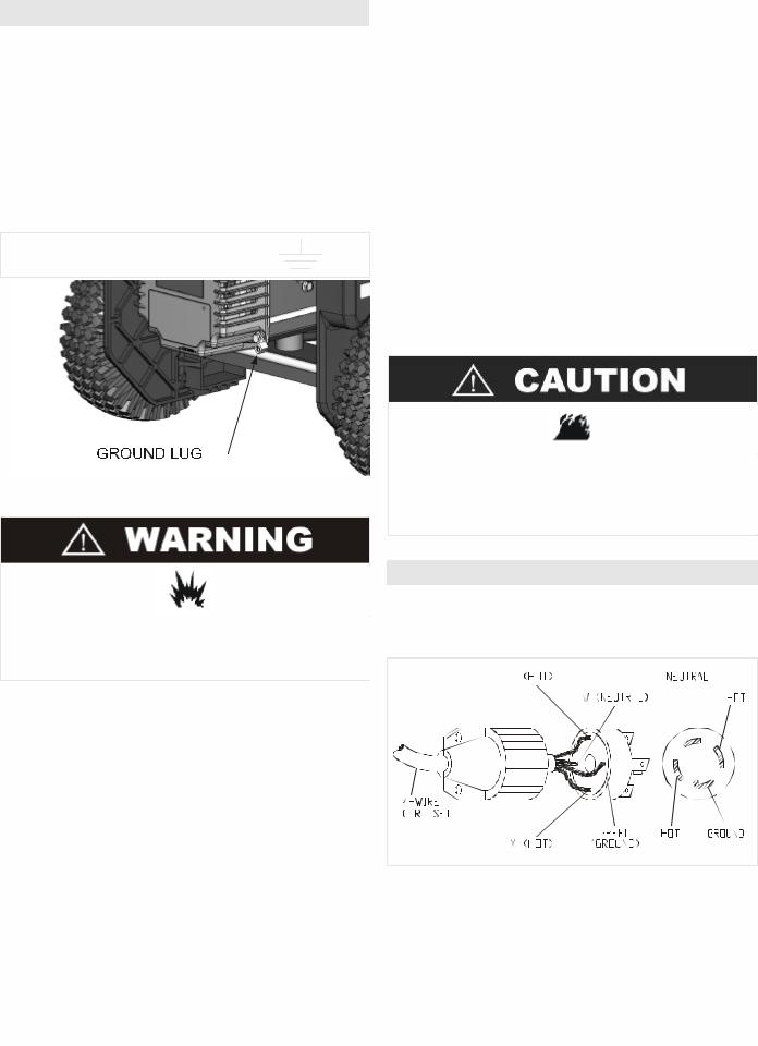
GROUNDING THE GENERATOR
The National Electric Code requires that this product be properly connected to an appropriate earth ground to help prevent electric shock. A ground terminal connected to the frame of the generator has been provided for this purpose. Connecting a length of heavy gauge (12 AWG min.) copper wire between the generator Ground Terminal and a copper rod driven into the ground should provide a suitable ground connection. However, consult with a local electrician to insure that local codes are being adhered to.
GROUND TERMINAL LOCATION:
LOW OIL SENSOR
The unit is equipped with a low oil sensor. If the oil level becomes lower than required, the sensor will activate a warning device or stop the engine. (See the accompanying engine manual for more information.)
If generator shuts off and the oil level is within specifications, check to see if generator is sitting at an angle that forces oil to shift. Place on an even surface to correct this. If engine fails to start, the oil level may not be sufficient to deactivate low oil level switch. Make sure the sump is completely full of oil.
FUEL
Fill the tank with clean, fresh unleaded automotive gasoline. Regular grade gasoline may be used provided a high octane rating is obtained (at least 85 pump octane). We recommend always using a fuel stabilizer. A fuel stabilizer will minimize the formulation of fuel gum deposits during storage. The fuel stabilizer can be added to the gasoline in the fuel tank, or into the gasoline in a storage container.
Do not overfill the tank. Keep maximum fuel level 1/4 inch below the top of the fuel tank. This will allow expansion in hot weather and prevent overflow.
Do not use a pipe carrying combustible material as the ground source.
LUBRICATION
DO NOT attempt to start this engine without filling the crank case with the proper amount and type of oil. (See the accompanying engine manual for this information.) Your generator has been shipped from the factory without oil in the crankcase. Operating the unit without oil can damage the engine.
Fill the engine with oil according to the engine manual. For units with a dipstick, fill oil to the proper level. Units without a dipstick should be filled to the top of the opening of the oil fill.
CORD-SET WIRING
If your generator is supplied with a 4-wire 120/240V twistlock receptacle, ground and neutral may be connected together at the load side.
www.powermate.com |
|
8 |
|
Customer Hotline 1-800-445-1805 |
|
|
|
|
|

MAJOR GENERATOR FEATURES
|
|
|
A. |
Control Panel |
Power Bar - This bargraph provides a quick visual indication of |
B. |
120 V, 20 Ampere Duplex Receptacle |
the percentage of rated output currently being supplied. |
|
20 amps of current may be drawn from each half of the |
% Load Indicator - This is a numeric version of the Power Bar. |
receptacle. However, total power drawn must be kept within |
Hour Meter - This indicates the total number of hours the |
|
nameplate ratings. These receptacles may be used along with the |
generator has run since manufacture. |
|
twistlock receptacle provided the generator is not overloaded. |
Maintenance Timer - This indicates the number of hours the |
|
C. |
120 Volt GFCI Receptacle |
generator has run since the last user reset. This timer should be reset |
|
Ground Fault Circuit Interrupter duplex receptacle is rated so |
after every oil change or any other maintenance task. Follow the |
that a total of 20 amps may be drawn regardless of whether both |
instructions in the engine owners manual for proper engine |
|
halves or just one receptacle is used. This receptacle may be used |
maintenance intervals. |
|
along with other receptacles provided the generator is not overloaded |
Reset Button - Pressing and holding this button will reset the |
|
and total power drawn is kept within nameplate ratings. |
Maintenance Timer to 0 HRS. |
|
Ground Fault Circuit Interrupter |
|
|
(Conforms to U.L 943, Class A and NEC requirements) |
|
|
This device protects you against hazardous electrical shock that may be caused if your body becomes a path through which electricity travels to reach ground. This could happen when you touch an appliance or cord that is “ live “ through faulty mechanism, damp or worn insulation, etc.
D.120/240 V, 30 Ampere Twistlock Receptacle
A maximum of 30 amps may be drawn from the 120/240 volt
receptacle, provided it is the only receptacle used. However, current |
|
|
|
|
|||
must be limited to the nameplate rating. If the 120/240 volt |
|
|
|
|
|||
receptacle is used along with the 120 volt receptacle, the total load |
|
|
|
|
|||
drawn must not exceed the nameplate ratings. |
|
|
|
|
|||
E. |
Circuit Breakers |
H. |
Fuel Shut-Off |
||||
|
The receptacles are protected by an AC circuit breaker. If the |
I. |
Engine On/Off Switch |
||||
generator is overloaded or an external short circuit occurs, the circuit |
J. |
Engine Choke Lever |
|||||
breaker will trip. If this occurs, disconnect all electrical loads and try |
K. |
Yamaha 10HP OHV Engine with: |
|||||
to determine the cause of the problem before attempting to use the |
|
Cast-Iron Cylinder Sleeve |
|||||
generator again. If overloading causes the circuit breaker to trip, |
|
Low Oil Sensor |
|||||
reduce the load. NOTE: Continuous tripping of the circuit |
L. |
7 Gallon Plastic Fuel Tank |
|||||
breaker may cause damage to generator or equipment. The |
M. |
Fuel Gauge |
|||||
circuit breaker may be reset by pushing the button of the breaker. |
N. |
Generator Head |
|||||
F. |
Panel Light |
O. |
Storage Bin |
||||
|
The panel light comes on automatically when the engine is |
P. |
Oil Drain |
||||
started. The light goes off automatically when the engine is shut off. |
Q. |
Pneumatic Tires |
|||||
G. |
DIGITECH™ Digital Information Center |
R. |
Retractable Handles |
||||
|
The DIGITECH™ Digital Information Center is a patented |
S. |
Handle Release Buttons |
||||
feature available only on select Coleman® Powermate® Brand |
|
To extend the handles, press the handle release buttons on the |
|||||
generators. |
wheel end of the unit. Pull the handles out until the handle release |
||||||
|
At a glance, the user can instantly see how much of the |
buttons lock in place on the engine end of the unit. |
|||||
generator's output capacity is being used and how much power |
|
To retract the handles, press the handle release buttons on the |
|||||
remains available. The display also indicates the time since last user |
engine end of the unit. Push the handles in until the |
||||||
reset and the total accumulated runtime of the generator. |
handle release buttons lock in place on the wheel end of the unit. |
||||||
|
|
|
|
|
|
||
www.powermate.com |
|
|
9 |
|
|
Customer Hotline 1-800-445-1805 |
|
|
|
|
|
|
|
|
|
STARTING THE UNIT
Gasoline is very dangerous.
Serious injury or death may result from fire caused by gasoline contacting hot surfaces.
1.Do not fill fuel tank with engine running.
2.Do not spill fuel while refilling tank.
3.Do not mix oil with gasoline.
4.Follow all instructions and warnings in the engine
manual.
PRE-START PREPARATION
Before starting the generator, check for loose or missing parts and for any damage which may have occurred during shipment.
This generator must not be operated without all factory installed heat shields in place. Failure to comply may cause the fuel tank to overheat and result in personal injury from fire.
STARTING THE ENGINE
1.Check oil level and fuel.
2.Disconnect all electrical loads from the unit.
3.Open fuel shut off valve.
4.Adjust choke as necessary.
5.Set the engine switch to the “ON" position.
6.Pull on the starter rope with fast steady pull. As the engine warms up, readjust the choke. On electric start models, turn the key switch to “START”. Release key switch after the engine starts.
Allow generator to run at no load for five minutes upon each initial start-up to permit engine and generator to stabilize.
•Provide adequate ventilation for toxic exhaust gases and cooling air flow.
•Do not start or run the generator in an enclosed area, even if door or windows are open.
•Engines give off carbon monoxide, an odorless, colorless, poison gas.
•Breathing carbon monoxide can cause nausea, fainting or death.
APPLYING LOAD
This unit has been pretested and adjusted to handle its full capacity. When starting the generator, disconnect all load. Apply load only after generator is running. Voltage is regulated via the engine speed adjusted at the factory for correct output. Readjusting will void warranty.
When applying a load, do not exceed the maximum wattage rating of the generator when using one or more receptacles. Also, do not exceed the amperage rating of any one receptacle.
SHUTTING THE GENERATOR OFF
1.Remove entire electrical load.
2.Let the engine run for two minutes without load.
3.Move the engine switch to the “OFF” position. (Turn the key switch to “OFF” on the electric start models).
4.Do not leave the generator until it has completely stopped.
5.Close the fuel shut off valve if the engine is to be put in storage or transported.
6.If a cover is used, do not install until unit has cooled.
www.powermate.com |
|
10 |
|
Customer Hotline 1-800-445-1805 |
|
|
|
|
|
BREAK-IN PROCEDURE |
4. |
Plug a lamp or light into the generator before starting the |
Controlled break-in helps insure proper engine and gener- |
|
engine. The light source will illuminate when voltage has |
ator operation. Follow engine procedure outlined in engine |
|
returned. |
manual. |
5. |
Start the engine with no load connected to the generator. |
|
6. |
Attach the "-" lead of the battery to the negative brush. |
|
|
Very briefly, touch the "+" lead of the battery to the |
|
|
positive brush as shown. Remove as soon as voltage |
|
|
builds up. To measure voltage, use a plug-in voltmeter. |
|
|
|
|
|
|
Do not apply heavy electrical load during break-in period (the first two to three hours of operations).
MAINTENANCE
GENERATOR: Brushes
The brushes in the generator should be inspected once every year for chips and cracks. Brushes should be replaced when they are worn to 1/4 inch (7mm).
NOTE: Replace brushes in sets only, never separately.
INSPECTING THE BRUSHES:
1.Remove cover plate (R).
2.Remove 4 stator bolts (U) and endbell.
3.Remove screws holding the protective plate on the inside of the endbell.
4.Disconnect the green (-) or blue (+) brush wires from the tab.
5.Remove brush mounting screws (S).
6.Slide brushes (T) from holders.
7.Replace if worn to 1/4 inch (7mm).
8.Do not over tighten screws.
NOTE: Replace only with brushes specified in parts list. Other brushes may appear to be identical but may have completely different mechanical and electrical characteristics.
EXCITING THE GENERATOR:
If there is a loss of residual magnetism (voltage will not build up), it may be necessary to re-excite the unit.
1.Use a 6-volt lantern battery (dry cell) or a 12-volt automotive battery.
2.Disconnect all loads from generator.
3.Remove the brush cover.
HEAT SHIELD:
Inspect to ensure that all heat shields and heat deflectors are intact and in place. Do not remove any parts or modify parts. Removing or modifying parts could cause serious damage to the unit.
ENGINE: Carburetor Icing
During the winter months, rare atmospheric conditions may develop which will cause an icing condition in the carburetor. If this develops, the engine may run rough, loose power, and may stall. Call Product Service for more information.
NOTE: Refer to the engine manufacturer's manual for service and maintenance of the engine.
QUICK STARTING TIPS FOR UNITS THAT HAVE BEEN SITTING FOR AWHILE:
If your unit has been sitting around for a long time period and is hard to start, try doing some of these easy steps before calling the Customer Hotline.
1.Check the oil level.
2.Replace the old fuel.
3.Change the spark plug.
4.Check the fuel lines. Make sure the fuel valve is open.
5.Check all generator parts for integrity.
6.Clean the Carburetor. (See engine manual for service centers)
www.powermate.com |
|
11 |
|
Customer Hotline 1-800-445-1805 |
|
|
|
|
|
 Loading...