


PM0497002
Insert
Additif
Adición
ELECTRIC GENERATOR - GROUPE ELECTROGENE - GENERADOR ELECTRICO
Thank you for selecting a Black Max™ Generator. The Black Max™ generator has been made to supply reliable, portable electrical power when utility power is not available. We hope you will enjoy your new generator.
Merci d'avoir choisi le groupe électrogène Black Max™. Ce groupe électrogène Black Max™ a été conçu pour fournir le pouvoir électrique, portatif et fiable quand le pouvoir d'utilité n'est pas disponible. Nous espérons que votre groupe électrogène vous donnera entière satisfaction.
Gracias por seleccionar un generador Black Max™. El generador Black Max™ ha sido diseñado para proporcionar energía eléctrica confiable y portátil cuando no hay servicio disponible de energía pública. Esperamos que disfrute de su nuevo generador.
IMPORTANT – Please make certain that persons who are to use this equipment thoroughly read and understand these instructions and any additional instructions provided prior to operation.
IMPORTANT - Prière de vous assurer que les personnes destinées à utiliser cet appareil ont pris soin d'en lire et d'en comprendre le mode d'emploi ou les directives avant de le mettre en marche.
IMPORTANTE. Asegúrese que las personas que utilizarán este equipo lean y entiendan completamente estas instrucciones y cualquier instrucción adicional proporcionada antes del funcionamiento.
|
|
www.powermate.com |
10/06 0064721 |
MAJOR GENERATOR FEATURES
*13 HP Honda OHV engine
*Cast-iron cylinder sleeve
*Low oil sensor
*Receptacles on control panel
*SERVTECH™ Digital Information Center
*CordKeeper™
*Automatic voltage regulator (AVR)
*8 gallon plastic fuel tank
*Portability Kit
CONTROL PANEL
A.120 V, 20 Ampere Duplex Receptacle
20 amps of current may be drawn from each half of the
receptacle. However, total power drawn must be kept within nameplate ratings. These receptacles may be used along with the twistlock receptacle provided the generator is not overloaded.
B.120/240 V, 30 Ampere Twistlock Receptacle
A maximum of 30 amps may be drawn from the 120/240
volt receptacle, provided it is the only receptacle used. However, current must be limited to the nameplate rating. If the
120/240 volt receptacle is used along with the 120 volt receptacle, the total load drawn must not exceed the nameplate ratings.
C.Circuit Breakers
The receptacles are protected by an AC circuit breaker. If the generator is overloaded or an external short circuit occurs, the circuit breaker will trip. If this occurs, disconnect all electrical loads and try to determine the cause of the problem before attempting to use the generator again. If overloading causes the circuit breaker to trip, reduce the load. NOTE: Continuous tripping of the circuit breaker may cause damage to generator or equipment.
The circuit breaker may be reset by pushing the button of the breaker.
D.Engine On/Off Switch
E.CordKeeper™ Restraint
The CordKeeper™ restraint is a unique feature used to
prevent plugs from being pulled out of the receptacles.
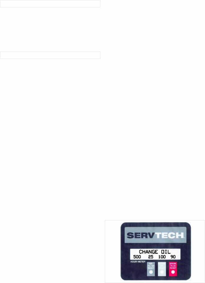
F.SERVTECH™ Generator Maintenance System
The SERVTECH™ Generator Maintenance System is a feature only on select Generator models manufactured by Powermate®.
At a glance, the user can instantly see the status of the most common maintenance items, such as air filter, engine oil and spark plug. The SERVTECH™ Maintenance Timers, alert you when maintenance is required for your generator to maintain optimum performance. The display also indicates the time since last user
maintenance reset and the total accumulated run time of the generator. In addition, to ensure safety and proper maintenance, tips scroll across to help users in generator service and operation.
HOUR METER - This indicates the total number of hours the generator has run since manufacture. This timer cannot be reset.
MAINTENANCE TIMERS (must be manually reset by the user after performing the indicated maintenance):
•Air Filter - This indicates the total number of hours the generator has run since the last air filter maintenance. The timer begins flashing at the suggested 50 hour interval, with the message "CHECK AIR FILTER", and will continue to flash until the user resets the timer with the convenient Reset Button.
•Engine Oil - This indicates the total number of hours the generator has run since the engine oil was last changed. The timer begins flashing at the suggested 100 hour interval, with the message "CHANGE OIL", and will continue to flash until the user resets the timer with the convenient Reset Button.
•Spark Plug - This indicates the total number of hours the generator has run since the last spark plug maintenance. This timer begins flashing at the suggested 100 hour interval, with the message "CHECK SPARK PLUG", and will continue to flash until the user resets the timer with the convenient Reset Button.
Note: Under extreme conditions, such as dirty, dusty and extreme temperatures, the engine manufacturer may recommend more frequent maintenance, than suggested by the timer intervals listed above. Please read the manufacturer's manual and always perform the required maintenance schedule as listed by the engine manufacturer.
RESET - When the user performs the suggested maintenance and wants to reset the Maintenance Timer, the Reset Button must be pressed and held for 3 seconds, under the field indicated on the display. The display indicates "HOLD TO RESET" while the Reset Button is pressed.
Engine Start - Each time the engine and generator is started, the display will warn the user of potential life threatening danger. It will display "*** DANGER! CARBON MONOXIDE - READ MANUAL". This message scrolls across the screen for 2 minutes.
Warm Up - A second message will then be displayed after the Engine Start event, suggesting to the user that they "PLUG IN LOADS, LARGEST LOAD FIRST".
This message will again scroll across the screen for 2 minutes.
After the Warm Up message, no message will be displayed until the next Maintenance Timer message.
|
|
English |
|
2 |
|||
|
|
PORTABILITY KIT INSTALLATION
TOOLS REQUIRED: 7/16”, 1/2” and 9/16" sockets and ratchets, block(s) of wood (minimum of 6” tall).
Refer to the parts list on page 9.
WHEEL INSTALLATION
1.Block up end of generator opposite the fuel tank cap to install wheel kit.
2.Insert wheel spacer (item 39) into the center of the wheel (item 28).
3.Slide 3/8 x 4.25” bolt (item 32) and 3/8 washer (item 27) through the wheel (item 28), then through the wheel bracket on the carrier, with the offset side of the wheel hub against the wheel bracket.
4.Thread 3/8 nyloc nut (item 33) onto the bolt and tighten to securely clamp the wheel assembly to the carrier.
5.Repeat above instructions for the remaining wheel.
FOOT INSTALLATION
1.Assemble the rubber feet (item 29) to the foot bracket (item 43) using a 1/4-20 x 1.5” bolt (item 11). Thread a 1/4 washer
(item 36) and a 1/4 nyloc nut (item 10) to the bolt to secure the assembly. Caution: Do not over tighten so that the foot material collapses.
2.Blocking up the alternator side of the generator, place the foot bracket under the carrier channel. Thread a 5/16-18 x 1” bolt (item 42) with a 5/16 wide washer (item 50) through the mounting holes and thread a 5/16 wide washer (item 50) and a 5/16 nyloc nut (item 13) to the bolt to secure the foot bracket to the carrier.
HANDLE INSTALLATION
1.Place handle (item 25) and spacer (item 46) on carrier on same end as feet, as shown in the diagram.
2.Slide 5/16 x 2.25” bolt (item 26) and 5/16 washers (item 12) through handle and handle bracket as shown in diagram and secure with 5/16” nyloc nut (item 13). Tighten until handle is securely clamped to the carrier.
3.Apply aerosol hairspray or similar adhesive to the handle (item 25), and then slide the handle grip (item 40) onto the handle. The aerosol hairspray will allow for easier assembly and will adhere the grip to the handle.
4.Insert cap (item 35) into end of handle (item 25).
5.Repeat above instructions for the remaining handle.
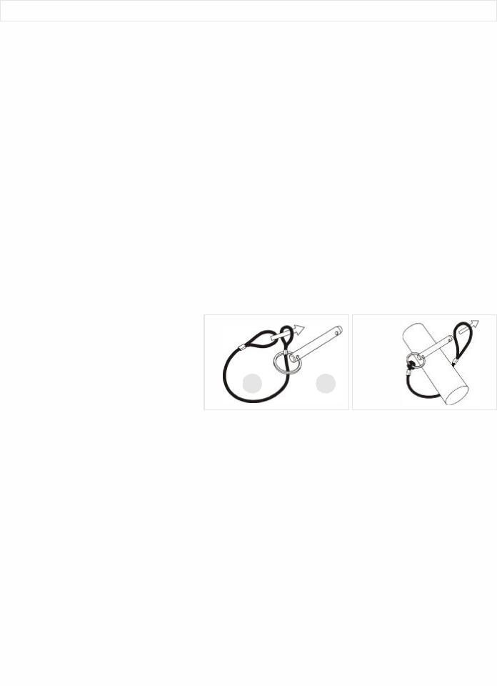
LOCKING HANDLE |
1 |
|
|
|
|
|
|
|
|
|
|
|
|
2 |
|||
1. |
Attach the lanyards (item 30) to the release |
|
|
|
|
|
||
|
pins (item 34) and carrier as shown in the |
|
|
|
|
|
|
|
|
illustration. |
|
|
|
|
|
|
|
|
|
|
|
|
|
|
|
|
2. |
To lock the handle (item 25) in the extended |
|
|
|
|
|
|
|
|
position, align the holes in the handle brackets |
|
|
|
|
|
|
|
|
30 |
34 |
|
|||||
|
with the holes in the carrier brackets and insert |
|
||||||
the release pins (item 34).
English |
|
3 |
|
||
|
|
|

LIMITED WARRANTY
Warranty Coverage: Powermate Corporation (the Company) warrants to the original retail customer in North America that it will repair or replace, free of charge, any parts found by the Company or its authorized service representative to be defective in material or workmanship. This warranty covers the cost of replacement parts and labor for defects in material or workmanship.
Not Covered:
·Transportation charges for sending the product to the Company or its authorized service representative for warranty service, or for shipping repaired or replacement products back to the customer; these charges must be borne by the customer.
·Engine is covered exclusively by a separate warranty from the engine manufacturer, included with the engine Manual.
·Damages caused by abuse or accident, and the effects of corrosion, erosion and normal wear and tear.
·Warranty is voided if the customer fails to install, maintain and operate the product in accordance with the instructions and recommendations of the Company set forth in the owner's manual, or if the product is used as rental equipment.
·The Company will not pay for repairs or adjustments to the product, or for any costs or labor, performed without the Company's prior authorization.
Warranty Period: Two (2) years from the date of purchase on products used solely for consumer applications; if a product is used for business or commercial applications, the warranty period will be limited to one (1) year from the date of purchase. For warranty service, the customer must provide dated proof of purchase and must notify the Company within the warranty period.
For warranty service: Call toll free 800-445-1805, or write to Powermate Corporation, Product Services, 4970 Airport Road, P. O. Box 6001, Kearney, NE 68848.
EXCLUSIONS AND LIMITATIONS: THE COMPANY MAKES NO OTHER WARRANTY OF ANY KIND, EXPRESS OR IMPLIED. IMPLIED WARRANTIES, INCLUDING WARRANTIES OF MERCHANTABILITY AND OF FITNESS FOR A PARTICULAR PURPOSE, ARE HEREBY DISCLAIMED. THE WARRANTY SERVICE DESCRIBED ABOVE IS THE EXCLUSIVE REMEDY UNDER THIS WARRANTY; LIABILITY FOR INCIDENTAL AND CONSEQUENTIAL DAMAGES IS EXCLUDED TO THE EXTENT PERMITTED BY LAW.
This warranty gives you specific legal rights, and you may also have other rights which vary from state to state. Some states do not allow a disclaimer of implied warranties, or the exclusion or limitation of incidental and consequential damages, so the above disclaimers and exclusions may not apply to you.
|
|
English |
|
4 |
|||
|
|

CARACTÉRISTIQUES PRINCIPALES DU
GROUPE ELECTROGENE
*Moteur 13 HP Honda OHV
*Chemise de cylindres en fonte
*Détecteur de bas niveau d'huile
*Prises sur tableau de commande
*Le centre d'information numérique SERVTECH™
*CordKeeper™
*La tension automatique régulatrice
*Réservoir de carburant en plastique d'une contenance de 30.3 litres (8 gallons)
*Kit de transport
TABLEAU DE COMMANDE
A.Prise double de 120 V, 20 A
20 ampères de courant peuvent être dessinés de chaque moitié
de la prise. La charge totale doit cependant rester dans les limites indiquées sur la plaque signalétique. Ces prises peuvent s’utiliser en conjonction avec la prise à verrouillage à condition que le générateur ne soit pas surchargée.
B.Prise à verrouillage de 120/240 V, 30 A
Cette prise de 120/240 V fournit un maximum de 30 A à
condition que ce soit la seule utilisée. La charge totale doit par ailleurs rester dans les limites indiquées sur la plaque signalétique. Si la prise de 120/240 V est utilisée en conjonction avec les prises de 120 V, la charge totale ne doit pas dépasser les limites indiquées sur la plaque.
C.Disjoncteurs
Les prises sont protégées par un disjoncteur alternatif. En cas de
surcharge ou de court-circuit extérieur, le disjoncteur saute. Si cela se produit, débrancher tout appareil relié au groupe électrogène et essayer de déterminer la cause du problème avant d’essayer de le réutiliser. Si le disjoncteur saute en raison d’une surcharge, réduire la charge. REMARQUE : Le groupe électrogène ou les appareils branchés dessus peuvent se trouver abîmés si le disjoncteur saute continuellement. Appuyer sur le bouton du disjoncteur pour le réenclencher.
D.Commutateur On/Off (Sur/De) du moteur
E.CordKeeper™ la Restriction
Le CordKeeper™ la restriction est un dispositif unique qui
empêche la fiche de ressortir accidentellement d’une prise.
F.Système d'entretien de génératrice SERVTECHMC
Le système d'entretien de génératrice SERVTECHMC est offert seulement pour certains modèles de génératrices fabriquées par
PowermateMD.
L'utilisateur peut voir immédiatement l'état des composants nécessitant un entretien périodique, tels que le filtre, l'huile à moteur et la bougie
d'allumage. Les minuteries d'entretien SERVTECHMC vous avertissent lorsque l'entretien de votre génératrice est requis, afin d'en assurer le rendement optimal. L'affichage indique également quand s'est faite la
dernière remise à zéro afférente à l'entretien et le temps de marche total accumulé par la génératrice. En outre, pour assurer la sécurité et un entretien approprié, des conseils sont affichés pour aider les utilisateurs à effectuer l'entretien et à utiliser la génératrice.
COMPTEUR HORAIRE - Ce dispositif indique le nombre total d'heures au cours desquelles la génératrice a été en marche depuis sa fabrication. Ce compteur horaire ne peut être remis à zéro.
MINUTERIES LIÉES À L'ENTRETIEN (doivent être remises à zéro manuellement par l'utilisateur une fois que l'entretien qui s'impose a été effectué) :
•Filtre à air - Ce dispositif indique le nombre total d'heures au cours desquelles la génératrice a été en marche depuis le dernier entretien du filtre à air. La minuterie se met à clignoter lorsque la périodicité suggérée de 50 heures est atteinte et le message "CHECK AIR FILTER" (vérifier le filtre à air) est affiché; cette minuterie continue de clignoter jusqu'à ce que l'utilisateur la remette à zéro à l'aide du bouton de remise à zéro pratique.
•Huile à moteur - Ce dispositif indique le nombre total d'heures au cours desquelles la génératrice a été en marche depuis le dernier renouvellement de l'huile à moteur. La minuterie se met à clignoter lorsque la périodicité suggérée de 100 heures est atteinte et le message "CHANGE OIL" (renouveler l'huile) est affiché; cette minuterie continue de clignoter jusqu'à ce que l'utilisateur la remette à zéro à l'aide du bouton de remise à zéro pratique.
•Bougie d'allumage - Ce dispositif indique le nombre total d'heures au cours desquelles la génératrice a été en marche depuis le dernier entretien de la bougie d'allumage. Cette minuterie se met à clignoter lorsque la périodicité suggérée de 100 heures est atteinte et le message "CHECK SPARK PLUG" (vérifier la bougie d'allumage) est affiché; cette minuterie continue de clignoter jusqu'à ce que l'utilisateur la remette à zéro à l'aide du bouton de remise à zéro pratique.
Nota : Dans des conditions extrêmes, telles que les environnements sales et poussiéreux, et les températures extrêmes, le fabricant du moteur pourrait recommander des périodicités d'entretien plus fréquentes que les périodicités précitées qui sont suggérées par la minuterie. Veuillez lire le guide du fabricant et respecter en tout temps le calendrier d'entretien précité, selon les directives du fabricant.
REMISE À ZÉRO - Lorsque l'utilisateur effectue l'entretien suggéré et qu'il désire remettre la minuterie d'entretien à zéro, il doit tenir le bouton de remise à zéro enfoncé pendant trois (3) secondes, sous le champ indiqué sur l'affichage. Les mots "HOLD TO RESET" (tenir enfoncé pour remettre à zéro) apparaissent sur l'affichage pendant que l'on enfonce le bouton de remise à zéro.
Démarrage du moteur - Chaque fois qu'on fait démarrer le moteur et la génératrice, l'affichage avertit l'utilisateur des dangers d'incendie possibles. Les mots "*** DANGER! CARBON MONOXIDE - READ MANUAL" (Danger! monoxyde de carbone - lire le manuel) sont affichés. Ce message défile à l'écran pendant deux (2) minutes.
Réchauffement - Un deuxième message est ensuite affiché une fois que le moteur est démarré, suggérant à l'utilisateur de brancher les charges, en commençant par la plus importante ("PLUG IN LOADS, LARGEST LOAD FIRST"). Ce message défile aussi à l'écran pendant deux (2) minutes.
Une fois le message de réchauffement affiché, aucun message n'est affiché jusqu'au moment où le prochain message de la minuterie d'entretien est affiché.
|
|
|
Français |
5 |
|
|
|
|
 Loading...