


|
|
|
|
|
|
|
|
|
|
|
|
|
|
|
|
|
|
|
|
|
|
|
|
|
|
|
|
|
|
|
|
|
|
|
|
|
|
|
|
|
|
|
|
|
|
|
|
|
|
|
|
|
|
|
|
|
|
|
|
|
|
|
|
|
|
|
|
|
|
|
|
|
|
|
|
|
|
|
|
|
|
|
|
|
|
|
|
|
|
|
|
|
|
|
|
|
|
|
|
|
|
|
|
|
|
|
|
|
|
|
|
|
|
|
|
|
|
|
|
|
|
|
|
|
|
|
|
|
|
|
|
|
|
|
|
|
|
|
|
|
|
|
|
|
|
|
|
|
|
|
|
|
|
|
|
|
|
|
|
|
|
|
|
|
|
|
|
|
|
|
|
|
|
|
|
|
|
|
|
|
|
|
|
|
|
|
|
|
|
|
|
|
|
|
© 2010 Polk Audio—all rights reserved |
1 |
|||||||||||
|
|
|
|
|
|
|
|
|
|
|
|
|
TABLE OF CONTENTS
INTRODUCTION. . . . . . . . . . . . . . . . . . . . . . . . . . . . . . . . . . . . . . . . . . . . . . . . . . . . . . . . . . . . . . . . . . . . . . . . . . . . . . . 4
WHAT’S IN THE BOX . . . . . . . . . . . . . . . . . . . . . . . . . . . . . . . . . . . . . . . . . . . . . . . . . . . . . . . . . . . . . . . . . . . . . . . . . . 4
LISTEN CAREFULLY . . . . . . . . . . . . . . . . . . . . . . . . . . . . . . . . . . . . . . . . . . . . . . . . . . . . . . . . . . . . . . . . . . . . . . . . . . . 4
TOOLS OF THE TRADE . . . . . . . . . . . . . . . . . . . . . . . . . . . . . . . . . . . . . . . . . . . . . . . . . . . . . . . . . . . . . . . . . . . . . . . . . 5
END PANEL LAYOUTS . . . . . . . . . . . . . . . . . . . . . . . . . . . . . . . . . . . . . . . . . . . . . . . . . . . . . . . . . . . . . . . . . . . . . . . . 5-8
Input Plate . . . . . . . . . . . . . . . . . . . . . . . . . . . . . . . . . . . . . . . . . . . . . . . . . . . . . . . . . . . . . . . . . . . . . . . . . . . . . . 5-7
Output Plate . . . . . . . . . . . . . . . . . . . . . . . . . . . . . . . . . . . . . . . . . . . . . . . . . . . . . . . . . . . . . . . . . . . . . . . . . . . . . 6-8
SPEAKER LEVEL HARNESSES . . . . . . . . . . . . . . . . . . . . . . . . . . . . . . . . . . . . . . . . . . . . . . . . . . . . . . . . . . . . . . . . . . 8
AMPLIFIER SETTINGS . . . . . . . . . . . . . . . . . . . . . . . . . . . . . . . . . . . . . . . . . . . . . . . . . . . . . . . . . . . . . . . . . . . . . . . . 8-9
Signal Input and Output Configurations . . . . . . . . . . . . . . . . . . . . . . . . . . . . . . . . . . . . . . . . . . . . . . . . . . . . . . . . 8
Phase Switches . . . . . . . . . . . . . . . . . . . . . . . . . . . . . . . . . . . . . . . . . . . . . . . . . . . . . . . . . . . . . . . . . . . . . . . . . . . 8
Auxiliary Output Configurations . . . . . . . . . . . . . . . . . . . . . . . . . . . . . . . . . . . . . . . . . . . . . . . . . . . . . . . . . . . . . . 9
Low-Pass Crossover. . . . . . . . . . . . . . . . . . . . . . . . . . . . . . . . . . . . . . . . . . . . . . . . . . . . . . . . . . . . . . . . . . . . . . . . 9
Remote Bass Operation . . . . . . . . . . . . . . . . . . . . . . . . . . . . . . . . . . . . . . . . . . . . . . . . . . . . . . . . . . . . . . . . . . . . . 9
High-Pass Crossover . . . . . . . . . . . . . . . . . . . . . . . . . . . . . . . . . . . . . . . . . . . . . . . . . . . . . . . . . . . . . . . . . . . . . . . 9
AMPLIFIER WIRING . . . . . . . . . . . . . . . . . . . . . . . . . . . . . . . . . . . . . . . . . . . . . . . . . . . . . . . . . . . . . . . . . . . . . . . . . 9-12 Power Connections for the Polk Audio PA330, PA660 and PA880 . . . . . . . . . . . . . . . . . . . . . . . . . . . . . . . . . . . . 9 Speaker Wiring Diagram PA330/PA660/PA880 . . . . . . . . . . . . . . . . . . . . . . . . . . . . . . . . . . . . . . . . . . . . . . . 10-12 Bridging . . . . . . . . . . . . . . . . . . . . . . . . . . . . . . . . . . . . . . . . . . . . . . . . . . . . . . . . . . . . . . . . . . . . . . . . . . . . . . 10-12
AMPLIFIER INSTALLATION . . . . . . . . . . . . . . . . . . . . . . . . . . . . . . . . . . . . . . . . . . . . . . . . . . . . . . . . . . . . . . . . . . 13-14
Choosing Mounting Locations . . . . . . . . . . . . . . . . . . . . . . . . . . . . . . . . . . . . . . . . . . . . . . . . . . . . . . . . . . . . . . . 13
Passenger Compartment . . . . . . . . . . . . . . . . . . . . . . . . . . . . . . . . . . . . . . . . . . . . . . . . . . . . . . . . . . . . . . . . . . . 13
Trunk Compartment . . . . . . . . . . . . . . . . . . . . . . . . . . . . . . . . . . . . . . . . . . . . . . . . . . . . . . . . . . . . . . . . . . . . . . . 13
General Precautions and Installation Tips . . . . . . . . . . . . . . . . . . . . . . . . . . . . . . . . . . . . . . . . . . . . . . . . . . . . . 13
Step By Step Installation. . . . . . . . . . . . . . . . . . . . . . . . . . . . . . . . . . . . . . . . . . . . . . . . . . . . . . . . . . . . . . . . . . . 14
SET UP AND TROUBLESHOOTING . . . . . . . . . . . . . . . . . . . . . . . . . . . . . . . . . . . . . . . . . . . . . . . . . . . . . . . . . . . 14-16
Testing the System . . . . . . . . . . . . . . . . . . . . . . . . . . . . . . . . . . . . . . . . . . . . . . . . . . . . . . . . . . . . . . . . . . . . . . . 14
Adjusting the Sound of the System . . . . . . . . . . . . . . . . . . . . . . . . . . . . . . . . . . . . . . . . . . . . . . . . . . . . . . . . . . 15
Troubleshooting Tips . . . . . . . . . . . . . . . . . . . . . . . . . . . . . . . . . . . . . . . . . . . . . . . . . . . . . . . . . . . . . . . . . . . . 15-16
SPECIFICATIONS. . . . . . . . . . . . . . . . . . . . . . . . . . . . . . . . . . . . . . . . . . . . . . . . . . . . . . . . . . . . . . . . . . . . . . . . . . . 17-18
FRANÇAIS . . . . . . . . . . . . . . . . . . . . . . . . . . . . . . . . . . . . . . . . . . . . . . . . . . . . . . . . . . . . . . . . . . . . . . . . . . . . . . . . 19-34
ESPAÑOL . . . . . . . . . . . . . . . . . . . . . . . . . . . . . . . . . . . . . . . . . . . . . . . . . . . . . . . . . . . . . . . . . . . . . . . . . . . . . . . . . 35-51
WARRANTY . . . . . . . . . . . . . . . . . . . . . . . . . . . . . . . . . . . . . . . . . . . . . . . . . . . . . . . . . . . . . . . . . . . . . . . . . . . . . . . . . 53
2 |
© 2010 Polk Audio—all rights reserved |
© 2010 Polk Audio—all rights reserved |
3 |

ENGLISH
INTRODUCTION
Thank you for your purchase of a Polk Audio PA power amplifier. Each Polk Audio PA amplifier is designed to be the leader in its class offering the most power, advanced features, and extreme ease of use. In high-end sound systems or high SPL systems, Polk Audio PA amplifiers will give you years of trouble-free performance.
ÊUÊ PA330—200 Watt: two-channel Class A/B amplifier with built-in fully variable high and low-pass crossover. The PA330 is capable of one-channel operation with a maximum power of 300 W into 4 Ohms.
ÊUÊ PA660—340 Watt: four-channel Class A/B amplifier with built-in fully variable low-pass crossover. Equipped with remote gain, the PA660 is capable of two-channel operation with a maximum power of 600 W when both the front and rear bridged channels are driven into 4 Ohms speaker loads.
ÊUÊ PA880—500 Watt: single-channel Class A/B amplifier with built-in fully variable low-pass crossover. Equipped with optional remote gain, the PA880 is capable of one-channel operation with a maximum power of 800 Watts into 2 Ohms.
The installation of all Polk Audio PA components will determine the overall performance result. Improper installation will not only limit the performance of your Polk Audio PA system but also potentially compromise the reliability of this amplifier. To ensure proper sonic results and component reliability, please refer to your authorized dealer for installation assistance or advice. If you decide to perform the installation yourself, be sure to read the entire manual before
beginning the installation.
WHAT’S IN THE BOX
ÊUÊ £®Ê « v iÀ
ÊUÊ {®Ê nÊÃi v Ì>«« }ÊL >V Ê* «ÃÊ i>`Ê«> Ê i>`ÊÃVÀiÜÃ
ÊUÊ £®Ê « v iÀÊ ÃÌ> >Ì Ê> `Ê «iÀ>Ì Ê > Õ>
ÊUÊ £®Ê*, £Ê,i ÌiÊL>ÃÃÊV ÌÀ Ê* nnäÊ Þ®
WARNING: LISTEN CAREFULLY
Polk Audio loudspeakers and subwoofers are capable of playing at extremely high volume levels, which could cause serious or permanent hearing damage. Polk Audio, Inc. accepts no liability for hearing loss, bodily injury or property damage resulting from the misuse of its products.
Keep these guidelines in mind and always use your own good judgment when controlling volume:
ÊUÊÊ9 ÕÊÃ Õ `Ê ÌÊ«À }i`ÊiÝ« ÃÕÀiÊÌ ÊÛ Õ iÃÊÌ >ÌÊiÝVii`ÊnxÊ`iV Li Ã` ®°Ê
ÊUÊÊ } ÊÛ Õ iÊ Ê> Ê>ÕÌ L iÊV> Ê `iÀÊÞ ÕÀÊ>L ÌÞÊÌ ÊÃ>vi ÞÊ «iÀ>ÌiÊ>ÊÛi V i°
ÊUÊÊ9 ÕÊ>ÀiÊÀië à L iÊv ÀÊ Ü }ÊÌ iÊ V> Ê >ÜÃÊ} ÛiÀ }Ê>VVi«Ì>L iÊ L iÊÛ Õ iÊ iÛi ð
For more about safe volume levels, go to: www.polkaudio.com/education/article/SPL/
ÊÊ "ÀÊÀiviÀÊÌ ÊÌ iÊ"VVÕ«>Ì > Ê i> Ì Ê> `Ê->viÌÞÊ ` ÃÌÀ>Ì Ê"- ®Ê}Õ `i iÃÊ>Ì\Ê www.osha.gov/dts/osta/otm/noise/standards_more.html
Model:__________________________________________________
Serial Number:____________________________________________
Date of Purchase:__________________________________________
TOOLS OF THE TRADE
Listed next are the majority of the tools required to perform an installation. Having the proper tools will make the installation that much easier. Some of these tools are necessities; some will just make the job easier.
Ê |
UÊ i Ê7Ài V iÃÊÓ ]ÊÎ ÊEÊ{ ®Ê |
U DMM or VOM |
||
Ê |
UÊ iVÌÀ VÊ`À ÊÜ Ì Ê>ÃÃ ÀÌi`Ê`À ÊL ÌÃÊ |
U Grommets |
||
Ê |
UÊ i>ÌÊÃ À ÊÌÕL }Ê |
|
U Marking pen |
|
Ê |
UÊ * «ÃÊ> `Êv >ÌÊL >`iÊÃVÀiÜÊ`À ÛiÀÃÊ |
U Nylon tie straps |
||
Ê |
UÊ * iÀÃÊÃÌ> `>À`Ê> `Ê ii` iÊ Ãi®Ê |
U Wire crimper |
||
Ê |
UÊ ,/ ÊÀi> ÊÌ iÊ> > ÞâiÀ®Ê |
|
U Wire cutters |
|
Ê |
UÊ - `iÀ }Ê À Ê> `ÊÃ `iÀÊ |
|
U Wire strippers |
|
Ê |
UÊ 1Ì ÌÞÊ viÊ |
Ê |
Ê |
Ê |
ÊUÊ 7 ÀiÊLÀÕÃ Ê ÀÊÃ> `«>«iÀÊv ÀÊV >ÃÃ ÃÊ}À Õ ` }
ÊUÊ ,iviÀi ViÊ ÊÜ Ì Ê£Ê âÊiÊ7>ÛiÊ>ÌÊä` Ê iÛi Ê> ÊL ÌÃÊ } ®
END PANEL LAYOUTS
PA330 Input Plate
|
1 |
|
2 |
|
3 |
4 |
|
|
|
5 |
|
6 |
|
7 |
|
|
8 |
|
9 |
|
|
|
|
|
|
||||||||||||||||||||
|
|
|
|
|
|
|
|
|
|
|
|
|
|
|
|
|
|
|
|
|
|
|
|
|
|
|
|
|
|
|
|
|
|
|
|
|
|
|
|
|
|
|
|
|
|
|
|
|
|
|
|
|
|
|
|
|
|
|
|
|
|
|
|
|
|
|
|
|
|
|
|
|
|
|
|
|
|
|
|
|
|
|
|
|
|
|
|
|
|
|
|
|
|
|
|
|
|
|
|
|
|
|
|
|
|
|
|
|
|
|
|
|
|
|
|
|
|
|
|
|
|
|
|
|
|
|
|
|
|
|
|
|
|
|
|
|
|
|
|
|
|
|
|
|
|
|
|
|
|
|
|
|
|
|
|
|
|
|
|
|
|
|
|
|
|
|
|
|
|
|
|
|
|
|
|
|
|
|
|
|
|
|
|
|
|
|
|
|
|
|
|
|
|
|
|
|
|
|
|
|
|
|
|
|
|
|
|
|
|
|
|
|
|
|
|
|
|
|
|
|
|
|
|
|
|
|
|
|
|
|
|
|
|
|
|
|
|
|
|
|
|
|
|
|
|
|
|
|
|
|
|
|
|
|
|
|
|
|
|
|
|
|
|
|
|
|
|
|
|
|
|
|
|
|
|
|
|
|
|
|
|
|
|
|
|
|
|
|
|
|
|
|
|
|
|
|
|
|
|
|
|
|
|
|
|
|
|
|
|
|
|
|
|
|
|
|
|
|
|
|
|
|
|
|
|
|
|
|
|
|
|
|
|
|
|
|
|
|
|
|
|
|
|
|
|
|
|
|
|
|
|
|
|
|
|
|
|
|
|
|
|
|
|
|
|
|
|
|
|
|
|
|
|
|
|
|
|
|
|
|
|
|
|
|
|
|
|
|
|
|
|
|
|
|
|
|
|
|
|
|
|
|
|
|
|
|
|
|
|
|
|
|
|
|
|
|
|
|
|
|
|
|
|
|
|
|
|
|
|
|
|
|
|
|
|
|
|
|
|
|
|
|
|
|
|
|
|
|
|
|
|
|
|
|
|
|
|
|
|
|
|
|
|
|
|
|
|
|
|
|
|
|
|
|
|
|
|
|
|
|
|
|
|
|
|
|
|
|
|
|
|
|
|
|
|
|
|
|
|
|
|
|
|
|
|
|
|
|
|
|
|
|
|
|
|
|
|
|
|
|
|
|
|
|
|
|
|
|
|
|
|
|
|
|
|
|
|
|
|
|
|
|
|
|
|
|
|
|
|
|
|
|
|
|
|
|
|
|
|
|
|
|
|
|
|
|
|
|
|
|
|
|
|
|
|
|
|
|
|
|
|
|
|
|
|
|
|
|
|
|
|
|
|
|
|
|
|
|
|
|
|
|
|
|
|
|
|
|
|
|
|
|
|
|
|
|
|
|
|
|
|
|
|
|
|
|
|
|
|
|
|
|
|
|
|
|
|
|
|
|
|
|
|
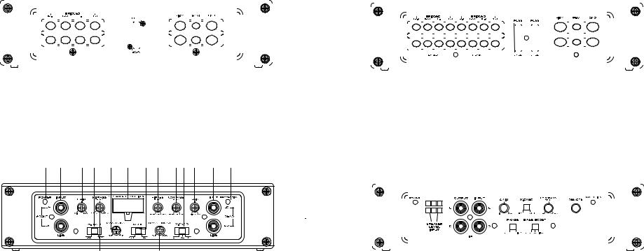
1.Power LED—When lit indicates that the amplifier is on.
2.Speaker Level Input—Connect speaker output from factory radio to amplifier; will auto sense signal from radio and turn amplifier on when needed; turn off after 1 minute without signal.
3.Line Level Inputs—Accepts line level input from a source unit, preamplifier, or equalizer.
4.Gain Control—Continuously adjusts from 175mV to 8V input to obtain full power output.
5.HPF, FULL, LPF Switch—Selects either high-pass crossover, full range, or low-pass crossover.
6.Low-Pass Frequency Control—Adjusts the frequency of the crossover.
7.High-Pass Frequency Control—Adjusts the frequency of the crossover.
8.Bass Boost Switch— ` ХГМГКL>ГГК}> К КМ АiiКГМi«ГКд` ]КИ` ]КEК£У` ®°
9.Status LED—Will indicate any fault condition in amplifier, also lights briefly during muting phase of turn-on.
4 |
© 2010 Polk Audio—all rights reserved |
© 2010 Polk Audio—all rights reserved |
5 |
PA330 Output Plate |
PA660 Output Plate |
|
|
|
|
|
|
|
|
1 |
|
|
|
|
2 |
|
|
3 |
4 |
5 |
|
|
|
|
|
|
|
|
|||||||||
|
|
|
|
|
|
|
|
|
|
|
|
|
|
|
|
|
|
|
|
|
|
|
|
|
|
|
|
|
|
|
|
|
|
|
|
|
|
|
|
|
|
|
|
|
|
|
|
|
|
|
|
|
|
|
|
|
|
|
|
|
|
|
|
|
|
|
|
|
|
|
|
|
|
|
|
|
|
|
|
|
|
|
|
|
|
|
|
|
|
|
|
|
|
|
|
|
|
|
|
|
|
|
|
|
|
|
|
|
|
|
|
|
|
|
|
|
|
|
|
|
|
|
|
|
|
|
|
|
|
|
|
|
|
|
|
|
|
|
|
|
|
|
|
|
|
|
|
|
|
|
|
|
|
|
|
|
|
|
|
|
|
|
|
|
|
|
|
|
|
|
|
|
|
|
|
|
|
|
|
|
|
|
|
|
|
|
|
|
|
|
|
|
|
|
|
|
|
|
|
|
|
|
|
|
|
|
|
|
|
|
|
|
|
|
|
|
|
|
|
|
|
|
|
|
|
|
|
|
|
|
|
|
|
|
|
|
|
|
|
|
|
|
|
|
|
|
|
|
|
|
|
|
|
|
|
|
|
|
|
|
|
|
|
|
|
|
|
|
|
|
|
|
|
|
|
|
|
|
|
|
|
|
|
|
|
|
|
|
|
|
|
|
|
|
|
|
|
|
|
|
|
|
|
|
|
|
|
|
|
|
|
|
|
|
|
|
|
|
|
|
|
|
|
|
|
|
|
|
|
|
|
|
|
|
|
|
|
|
|
|
|
|
|
|
|
|
|
|
|
|
|
|
|
|
|
|
|
|
|
|
|
|
|
|
|
|
|
|
|
|
|
|
|
|
|
|
|
|
|
|
|
|
|
|
|
|
|
|
|
|
|
|
|
|
|
|
|
|
|
|
|
|
|
|
|
|
|
|
|
|
|
|
|
|
|
|
|
|
|
|
|
|
|
|
|
|
|
|
|
|
|
|
|
|
|
|
|
|
|
|
|
|
|
|
|
|
|
|
|
|
|
|
|
|
|
|
|
|
|
|
|
|
|
|
|
|
|
|
|
|
|
|
|
|
|
|
|
|
|
|
|
|
|
|
|
|
|
|
|
|
|
|
|
|
|
|
|
|
|
|
|
|
|
|
|
|
|
|
|
|
|
|
|
|
|
|
|
|
|
|
|
|
|
|
|
|
|
|
|
|
|
|
|
|
|
|
|
|
|
|
|
|
|
|
|
|
|
|
|
|
|
|
|
|
|
|
|
|
|
|
|
|
|
|
|
|
|
|
|
|
|
|
|
|
|
|
1 |
|
|
|
|
|
|
|
|
2 |
|
|
2 |
|
3 |
|
4 |
5 |
|
|
|
|
|
|
|
|
|||||||||||||||||||||||
|
|
|
|
|
|
|
|
|
|
|
|
|
|
|
|
|
|
|
|
|
|
|
|
|
|
|
|
|
|
|
|
|
|
|
|
|
|
|
|
|
|
|
|
|
|
|
|
|
|
|
|
|
|
|
|
|
|
|
|
|
|
|
|
|
|
|
|
|
|
|
|
|
|
|
|
|
|
|
|
|
|
|
|
|
|
|
|
|
|
|
|
|
|
|
|
|
|
|
|
|
|
|
|
|
|
|
|
|
|
|
|
|
|
|
|
|
|
|
|
|
|
|
|
|
|
|
|
|
|
|
|
|
|
|
|
|
|
|
|
|
|
|
|
|
|
|
|
|
|
|
|
|
|
|
|
|
|
|
|
|
|
|
|
|
|
|
|
|
|
|
|
|
|
|
|
|
|
|
|
|
|
|
|
|
|
|
|
|
|
|
|
|
|
|
|
|
|
|
|
|
|
|
|
|
|
|
|
|
|
|
|
|
|
|
|
|
|
|
|
|
|
|
|
|
|
|
|
|
|
|
|
|
|
|
|
|
|
|
|
|
|
|
|
|
|
|
|
|
|
|
|
|
|
|
|
|
|
|
|
|
|
|
|
|
|
|
|
|
|
|
|
|
|
|
|
|
|
|
|
|
|
|
|
|
|
|
|
|
|
|
|
|
|
|
|
|
|
|
|
|
|
|
|
|
|
|
|
|
|
|
|
|
|
|
|
|
|
|
|
|
|
|
|
|
|
|
|
|
|
|
|
|
|
|
|
|
|
|
|
|
|
|
|
|
|
|
|
|
|
|
|
|
|
|
|
|
|
|
|
|
|
|
|
|
|
|
|
|
|
|
|
|
|
|
|
|
|
|
|
|
|
|
|
|
|
|
|
|
|
|
|
|
|
|
|
|
|
|
|
|
|
|
|
|
|
|
|
|
|
|
|
|
|
|
|
|
|
|
|
|
|
|
|
|
|
|
|
|
|
|
|
|
|
|
|
|
|
|
|
|
|
|
|
|
|
|
|
|
|
|
|
|
|
|
|
|
|
|
|
|
|
|
|
|
|
|
|
|
|
|
|
|
|
|
|
|
|
|
|
|
|
|
|
|
|
|
|
|
|
|
|
|
|
|
|
|
|
|
|
|
|
|
|
|
|
|
|
|
|
|
|
|
|
|
|
|
|
|
|
|
|
|
|
|
|
|
|
|
|
|
|
|
|
|
|
|
|
|
|
|
|
|
|
|
|
|
|
|
|
|
|
|
|
|
|
|
|
|
|
|
|
|
|
|
|
|
|
|
|
|
|
|
|
|
|
|
|
|
|
|
|
|
|
|
|
|
|
|
|
|
|
|
|
|
|
|
|
|
|
|
|
|
|
|
|
|
|
|
|
|
|
|
|
|
|
|
|
|
|
|
|
|
|
|
|
|
|
|
|
|
|
|
|
|
|
|
|
|
|
|
|
|
|
|
|
|
|
|
|
|
|
|
|
|
|
|
|
|
|
|
|
|
|
|
|
|
|
|
|
|
|
|
|
|
|
|
|
|
|
|
|
|
|
|
|
|
|
|
|
|
|
|
|
|
|
|
|
|
|
|
|
|
|
|
|
|
|
|
|
|
|
|
|
|
|
|
|
|
|
|
|
|
|
|
|
|
|
|
|
|
|
|
|
|
|
|
|
|
|
|
|
|
|
|
|
|
|
|
|
|
|
|
|
|
|
|
|
|
|
|
|
|
|
|
|
|
|
|
|
|
|
|
|
|
|
|
|
|
|
|
|
|
|
|
|
|
|
|
|
|
|
|
|
|
|
|
|
|
|
1.Speaker Connections—accepts up to 12 AWG speaker wire.
2.1 ATC Fuse—protects the amplifier from over current situations.
3.Power Connections—accepts up to 4 AWG power cables.
4.REM Remote Turn-on Input—turns on the amplifier when fed 12 V+.
5.Ground Connection—accepts up to 4 AWG ground cable.
PA660 Input Plate
1 |
2 |
3 |
4 |
5 |
6 |
7 |
8 |
9 10 |
11 |
12 |
13 |
14 |
15 |
1.Power LED—when lit indicates that the amplifier is on.
2.Line Level Front Inputs—accepts line level input from the front channels of a source unit.
3.Front Gain Control—continuously adjusts from 250mV to 5V for full front channel output power.
4.Front FULL, HPF Switch—selects either high-pass crossover or full range for front channels.
5.Front Variable Bass Control—adjusts bass gain on front channels from 0dB to +8dB.
6.Speaker Level Input—connect speaker output from factory radio to amplifier; will auto-sense signal from radio and turn amplifier on when needed; turn off after 1 minute without signal.
7.2 Ch / 4 Ch Switch—allows all amplifier channels to have input from either 2 channel input
ÊÊ vÀ Ì®Ê ÀÊ> Ê{ÊV > i Ê «ÕÌÃ
8.Rear High-Pass Crossover Frequency Control—adjusts the frequency of the rear channels high-pass crossover.
9.Rear Low-Pass Crossover Frequency Control—adjusts the frequency of the rear channels low-pass crossover.
10.Rear LPF, FULL, HPF Switch—selects either low-pass crossover, full range or high-pass crossover for rear channels.
11.Rear Gain Control—continuously adjusts from 250mV to 5V for full rear channel output power.
12.Line Level Rear Inputs—accepts line level input from the rear channels of a source unit.
13.Status LED—will indicate any fault condition in amplifier, also lights briefly during muting phase of turn-on.
14.Front High Pass Crossover Frequency Control—adjusts the frequency of the front channels high-pass crossover.
15.Rear Variable Bass Control—adjusts bass gain on rear channels from 0dB to +8dB.
1.Speaker Connections—accepts up to 12 AWG speaker wire.
2.2 ATC Fuses—protects the amplifier from over current situations.
3.Power Connections—accepts up to 4 AWG power cables.
4.REM Remote Turn-on Input—turns on/off the amplifier when fed 12 V+.
5.Ground Connection—accepts up to 4 AWG ground cable.
PA880 Input Plate
|
|
|
|
|
|
1 |
|
|
2 |
|
|
3 |
4 |
|
5 |
6 |
|
|
7 |
|
8 |
|
|
|
|
9 |
10 |
11 |
|
|
|
|
|
|
||||||||||||||||
|
|
|
|
|
|
|
|
|
|
|
|
|
|
|
|
|
|
|
|
|
|
|
|
|
|
|
|
|
|
|
|
|
|
|
|
|
|
|
|
|
|
|
|
|
|
|
|
|
|
|
|
|
|
|
|
|
|
|
|
|
|
|
|
|
|
|
|
|
|
|
|
|
|
|
|
|
|
|
|
|
|
|
|
|
|
|
|
|
|
|
|
|
|
|
|
|
|
|
|
|
|
|
|
|
|
|
|
|
|
|
|
|
|
|
|
|
|
|
|
|
|
|
|
|
|
|
|
|
|
|
|
|
|
|
|
|
|
|
|
|
|
|
|
|
|
|
|
|
|
|
|
|
|
|
|
|
|
|
|
|
|
|
|
|
|
|
|
|
|
|
|
|
|
|
|
|
|
|
|
|
|
|
|
|
|
|
|
|
|
|
|
|
|
|
|
|
|
|
|
|
|
|
|
|
|
|
|
|
|
|
|
|
|
|
|
|
|
|
|
|
|
|
|
|
|
|
|
|
|
|
|
|
|
|
|
|
|
|
|
|
|
|
|
|
|
|
|
|
|
|
|
|
|
|
|
|
|
|
|
|
|
|
|
|
|
|
|
|
|
|
|
|
|
|
|
|
|
|
|
|
|
|
|
|
|
|
|
|
|
|
|
|
|
|
|
|
|
|
|
|
|
|
|
|
|
|
|
|
|
|
|
|
|
|
|
|
|
|
|
|
|
|
|
|
|
|
|
|
|
|
|
|
|
|
|
|
|
|
|
|
|
|
|
|
|
|
|
|
|
|
|
|
|
|
|
|
|
|
|
|
|
|
|
|
|
|
|
|
|
|
|
|
|
|
|
|
|
|
|
|
|
|
|
|
|
|
|
|
|
|
|
|
|
|
|
|
|
|
|
|
|
|
|
|
|
|
|
|
|
|
|
|
|
|
|
|
|
|
|
|
|
|
|
|
|
|
|
|
|
|
|
|
|
|
|
|
|
|
|
|
|
|
|
|
|
|
|
|
|
|
|
|
|
|
|
|
|
|
|
|
|
|
|
|
|
|
|
|
|
|
|
|
|
|
|
|
|
|
|
|
|
|
|
|
|
|
|
|
|
|
|
|
|
|
|
|
|
|
|
|
|
|
|
|
|
|
|
|
|
|
|
|
|
|
|
|
|
|
|
|
|
|
|
|
|
|
|
|
|
|
|
|
|
|
|
|
|
|
|
|
|
|
|
|
|
|
|
|
|
|
|
|
|
|
|
|
|
|
|
|
|
|
|
|
|
|
|
|
|
|
|
|
|
|
|
|
|
|
|
|
|
|
|
|
|
|
|
|
|
|
|
|
|
|
|
|
|
|
|
|
|
|
|
|
|
|
|
|
|
|
|
|
|
|
|
|
|
|
|
|
|
|
|
|
|
|
|
|
|
|
|
|
|
|
|
|
|
|
|
|
|
|
|
|
|
|
|
|
|
|
|
|
|
|
|
|
|
|
|
|
|
|
1.Power LED—when lit indicates that the amplifier is on.
2.Speaker Level Input—connect speaker output from factory radio to amplifier, will auto sense signal from radio and turn amplifier on when needed, turn off after 1 minute without signal.
3.Line Level Outputs—provides a full range signal for easy connection to additional amplifiers.
4.Line Level Inputs—accepts Line level input from a source unit, preamplifier, or equalizer.
5.Gain Control—continuously adjusts from 150mV to 8V input to obtain full power output.
6.Phase Control Switch—Allows for adjustment of phase and makes bridging amplifiers possible.
7.LPF, FULL, Switch—Selects either low-pass crossover or full range crossover.
8.Bass Boost Switch— ` ХГМГКL>ГГК}> К КМ АiiКГМi«ГКд` ]КИ` ]КEК£У` ®°
9.Low-Pass Crossover Frequency Control—adjusts the frequency of the crossover.
10.Remote Bass Gain Jack—V iVÌÃÊ*, £ÊÀi ÌiÊL>ÃÃÊV ÌÀ ®°
11.Status LED—Will indicate any fault condition in amplifier, also lights briefly during muting phase of turn-on.
6 |
© 2010 Polk Audio—all rights reserved |
© 2010 Polk Audio—all rights reserved |
7 |
PA880 Output Plate
|
|
|
|
|
|
|
|
1 |
|
|
2 |
2 |
|
|
3 |
4 |
5 |
|
|
|
|
|
|
|
|
|||||||||
|
|
|
|
|
|
|
|
|
|
|
|
|
|
|
|
|
|
|
|
|
|
|
|
|
|
|
|
|
|
|
|
|
|
|
|
|
|
|
|
|
|
|
|
|
|
|
|
|
|
|
|
|
|
|
|
|
|
|
|
|
|
|
|
|
|
|
|
|
|
|
|
|
|
|
|
|
|
|
|
|
|
|
|
|
|
|
|
|
|
|
|
|
|
|
|
|
|
|
|
|
|
|
|
|
|
|
|
|
|
|
|
|
|
|
|
|
|
|
|
|
|
|
|
|
|
|
|
|
|
|
|
|
|
|
|
|
|
|
|
|
|
|
|
|
|
|
|
|
|
|
|
|
|
|
|
|
|
|
|
|
|
|
|
|
|
|
|
|
|
|
|
|
|
|
|
|
|
|
|
|
|
|
|
|
|
|
|
|
|
|
|
|
|
|
|
|
|
|
|
|
|
|
|
|
|
|
|
|
|
|
|
|
|
|
|
|
|
|
|
|
|
|
|
|
|
|
|
|
|
|
|
|
|
|
|
|
|
|
|
|
|
|
|
|
|
|
|
|
|
|
|
|
|
|
|
|
|
|
|
|
|
|
|
|
|
|
|
|
|
|
|
|
|
|
|
|
|
|
|
|
|
|
|
|
|
|
|
|
|
|
|
|
|
|
|
|
|
|
|
|
|
|
|
|
|
|
|
|
|
|
|
|
|
|
|
|
|
|
|
|
|
|
|
|
|
|
|
|
|
|
|
|
|
|
|
|
|
|
|
|
|
|
|
|
|
|
|
|
|
|
|
|
|
|
|
|
|
|
|
|
|
|
|
|
|
|
|
|
|
|
|
|
|
|
|
|
|
|
|
|
|
|
|
|
|
|
|
|
|
|
|
|
|
|
|
|
|
|
|
|
|
|
|
|
|
|
|
|
|
|
|
|
|
|
|
|
|
|
|
|
|
|
|
|
|
|
|
|
|
|
|
|
|
|
|
|
|
|
|
|
|
|
|
|
|
|
|
|
|
|
|
|
|
|
|
|
|
|
|
|
|
|
|
|
|
|
|
|
|
|
|
|
|
|
|
|
|
|
|
|
|
|
|
|
|
|
|
|
|
|
|
|
|
|
|
|
|
|
|
|
|
|
|
|
|
|
|
|
|
|
|
|
|
|
|
|
|
|
|
|
|
|
|
|
|
|
|
|
|
|
|
|
|
|
|
|
|
|
|
|
|
|
|
|
|
|
|
|
|
|
|
|
|
|
|
|
|
|
|
1.Speaker Connections—accepts up to 12 AWG speaker wire.
2.2 ATC Fuses—protects the amplifier from over current situations.
3.Power Connections—accepts up to 4 AWG power cables.
4.REM Remote Turn-on Input—turns on/off the amplifier when fed Switched 9-15 V+.
5.Ground Connection—accepts up to 4 AWG ground cable.
SPEAKER LEVEL HARNESSES
Do not connect the high level input connections to power, signal, or chassis ground as damage to the head-unit outputs may result. The high-level inputs are designed to work with either grounded or BTL speaker level outputs
v Õ `Ê Ê ÃÌÊ i>`ÊÕ Ìî°Ê
SPEAKER LEVEL CONNECTIONS
WIRE COLOR |
INPUT CONNECTION |
|
|
Black |
Ground |
|
|
White |
+ Left Front channel |
|
|
White/Black |
- Left Front channel |
|
|
Green/Black |
- Right Rear channel |
|
|
Green |
+ Right Rear channel |
|
|
Gray |
+ Right Front channel |
|
|
Gray/Black |
- Right Front channel |
|
|
Violet/Black |
- Left Rear channel |
|
|
Violet |
+ Left Rear channel |
|
|
AMPLIFIER SETTINGS
Signal Input and Output Configurations
The input section of the amplifier consists of a phase switch that sets the output configuration, gain controls, and line level inputs. The input section makes it easy to adapt this amplifier to most system configurations.
Phase Switches * nnä®
ÊUÊ 0°—leaves output unaffected. The output signal is in phase with the input signal.
ÊUÊ 180°—inverts the output. The channel is 180° out of phase. This configuration is useful for inverting the phase of subwoofers to improve staging in a vehicle. This is also used when bridging two amplifiers into one speaker.
Auxiliary Output Configurations * nnä®
The auxiliary outputs on Polk Audio PA amplifiers offer easy, unlimited system expansion. Routing signal from a source unit, pre-amplifier, or equalizer is a matter of connecting cables to the line level inputs and the line level outputs to your next Polk Audio PA amplifier in the signal chain. The signal passes through a buffer stage so that several amplifiers can be daisy chained without signal loss or overloading of the source unit. This maximizes the signal output and minimizes the potential for system noise.
Low-Pass Crossover
/ iÊ Ü «>ÃÃÊVÀ Ãà ÛiÀÊ ÃÊ>VÌ ÛiÊÜ Ì Ê>ÊÓ `Ê À`iÀÊ£Ó` Ê«iÀÊ VÌ>Ûi®Êà «i°Ê/ iÊ Ü «>ÃÃÊVÀ Ãà ÛiÀÊ is continuously variable from 50Hz to 500Hz.
Remote Bass Operation * nnä®
The remote bass port provides easy remote access to the internal bass gain structure of the power amplifier. The bass gain is centered at 44Hz. The PRGC-1 plugs into the amplifier via the 1/8" mini jack plug. The PRGC-1 can be installed in the front of the vehicle to control the amplifier bass gain level. The PRGC-1 can be used
as a bass level control when used on an amplifier dedicated to subwoofers.
High-Pass Crossover * ÎÎäÉ* ÈÈä® 7 i ÊÌ iÊÃÜ ÌV Ê ÃÊÌ ÊÌ iÊ ivÌÊ 1 Ê« Ã Ì ®]ÊÌ iÊ } «>ÃÃÊVÀ Ãà ÛiÀÊ ÃÊLÞ«>ÃÃi`°Ê7 i ÊÌ iÊÃÜ ÌV Ê ÃÊÌ ÊÌ iÊÀ } ÌÊ * Ê« Ã Ì ®]ÊÌ iÊ } «>ÃÃÊVÀ Ãà ÛiÀÊ ÃÊ>VÌ Ûi°Ê/ iÊ } «>ÃÃÊVÀ Ãà ÛiÀÊ ÃÊV Ì Õ Õà ÞÊÛ>À >L iÊvÀ Êxä âÊÌ Êxää â°
AMPLIFIER WIRING
Power Connections for the Polk Audio PA330, PA660 and PA880
ÊUÊ * Ê Õ` Ê* ÎÎäÊ ÕÃiÊâi\Ê£ÊÝÊÓxÊ *Ê / °Ê
ÊUК * К Х` К* ИИдК ХГiКвi\КУКЭКУxК *К / °К
ÊUК * К Х` К* nnдК ХГiКвi\КУКЭКОдК *К / °
ÊUÊ * ÜiÀÊV iVÌ ÃÊ>VVi«ÌÊÕ«ÊÌ Ê{Ê 7 ÊÜ Ài°
ÊUÊ {Ê 7 Ê« ÜiÀÊ> `Ê}À Õ `ÊÜ ÀiÊÀiV i `i`Êv ÀÊ «Ì > Ê«iÀv À > Vi°
ÊUÊ iVÌÊ£Ó6³ÊÌ ÊÌ iÊL>ÌÌiÀÞÊÌ À Õ} ÊvÕÃiÊ `iÀ°Ê/ ÃÊV iVÌ Ê«À Û `iÃʳ£Ó6Ê > Ê« ÜiÀÊÌ ÊÌ iÊ> « v iÀ°
ÊUÊ * ÜiÀÊÜ ÀiÊ ÕÃÌÊLiÊvÕÃi`Ê Ê ÀiÊÌ > Ê£n¸ÊvÀ ÊL>ÌÌiÀÞ°
ÊUÊ À Õ `Ê> « v iÀÊÌ Ê>Ê} `ÊV >ÃÃ ÃÊ}À Õ `Ê>ÃÊV ÃiÊ>ÃÊ« ÃÃ L iÊÌ ÊÌ iÊ> « v iÀ°
ÊUÊ iVÌÊ, ÊÌiÀ > ÊÌ ÊÀi ÌiÊÌÕÀ Ê i>`ÊvÀ ÊÃ ÕÀViÊÕ Ì°Ê/ ÃÊV iVÌ Ê«À Û `iÃÊ
+12V power to turn-on the amplifier.
Ê UÊ ``ÊiÝÌÀ>Ê}À Õ `ÊÜ ÀiÊLiÌÜii ÊÌ iÊ i}>Ì ÛiÊÌiÀ > Ê vÊÌ iÊL>ÌÌiÀÞÊ> `ÊÌ iÊV >Ãà ð
8 |
© 2010 Polk Audio—all rights reserved |
© 2010 Polk Audio—all rights reserved |
9 |

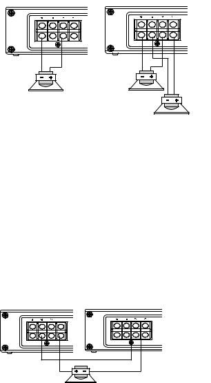
Speaker Wiring Diagram PA330
The Polk Audio PA330 amplifier offers two positive and two negative output terminals for ease of connecting the speakers to the amplifier. Each amplifier is stable to 2 Ohm per channel or 4 Ohm bridged.
Bridged |
Stereo |
4 |
2 4 |
|
2 4 |
4
Tri-mode
For Tri-mode wiring the high frequency speakers should be run in stereo
> `ÊÕÃiÊ>Ê«>Ãà ÛiÊ Ê iÊVÀ Ãà ÛiÀÊV>«>V Ì À®ÊÜ Ì Êi>V ÊÌ ÊÀi ÛiÊÌ iÊ low frequency. The mono low frequency speaker would be connected in the bridge mode to the two stereo channels with a in line passive
VÀ Ãà ÛiÀÊ `ÕVÌ À®ÊÌ ÊÀi ÛiÊÌ iÊ } ÊvÀiµÕi V iðÊ/ iÊ } ÊvÀiµÕi VÞÊ speakers should be no less than 2 Ohm and the low frequency speaker should be no less than 4 Ohm.
Bridging
For bridging into a single speaker load, the Polk Audio PA330 has the ability to bridge the front or rear channels together. The impedance of the speaker must not be less than 4 Ohm.
Tri-mode
Bridged
2 4
2 4
Speaker Wiring Diagram PA660
/ iК* К Х` К* ИИдК> « v iАК vviАГКМЬ КГiМГКvА МК> `КАi>А®К vКМЬ К« Г М ЫiК> `КМЬ К i}>М ЫiК ХМ«ХМКМiА > ГКv АКi>ГiК of connecting the speakers to the amplifier. Each amplifier is stable to 2 Ohm per channel or 4 Ohm per bridged channel pair.
2 channels Bridged Front & Rear
bridged |
bridged |
4 channel
2 4 |
2 4 |
4 8 4 8 


 2 4 2 4
Tri-mode
For Tri-mode wiring the high frequency speakers should be run
ÊÃÌiÀi Ê> `ÊÕÃiÊ>Ê«>Ãà ÛiÊ Ê iÊVÀ Ãà ÛiÀÊV>«>V Ì À®ÊÜ Ì Ê each to remove the low frequency. The mono low frequency speaker would be connected in the bridge mode to the two
ÃÌiÀi ÊV > i ÃÊÜ Ì Ê>Ê Ê iÊ«>Ãà ÛiÊVÀ Ãà ÛiÀÊ `ÕVÌ À®ÊÌ Ê remove the high frequencies. The high frequency speakers
Ã Õ `ÊLiÊ Ê iÃÃÊÌ > ÊÓÊ" Ê> `ÊÌ iÊ ÜÊvÀiµÕi VÞÊLÀ `}i`®Ê speaker should be no less than 4 Ohm.
Bridging
For bridging into a single speaker load, the Polk Audio PA660 has the ability to bridge the front or rear channels together. The impedance of the speaker must not be less than 4 Ohm.
4 4
Front and Rear
in Tri-mode
bridged |
bridged |
2 4 |
2 4 |
2 4 2 4
10 |
© 2010 Polk Audio—all rights reserved |
© 2010 Polk Audio—all rights reserved |
11 |
Speaker Wiring Diagram PA880
The Polk Audio PA880 amplifier offers two positive and two negative output terminals for ease of connecting the speakers to
the amplifier. Since these are mono amplifiers, the speaker connectors are paralleled internally. Each amplifier is stable to 2 Ohm.
Single 2 Ohm speaker |
or 2 ea. of 4 Ohm speakers |
2 4 |
4 |
|
4 |
Bridging
For bridging into a single speaker load, the Polk Audio PA880 have the ability to be bridged with another amplifier
vКМ iКГ> iК `i °К/ К` КМ ГКЮ ХК ХГМКГiМКМ iК* - КГЬ МV К КМ iКГ >Ыi®К> «]К ЫiКМ iК« >ГiКГЬ МV КvА
0 to 180, exactly opposite of the master amp. Refer to the Phase Switch section of this guide.
Be sure to set all adjustment on both amplifiers exactly the same except for the phase switch. The phase switch on the
>ÃÌiÀÊ> « v iÀÊÃ Õ `ÊLiÊäÊ> `ÊÌ iÊà >ÛiÊ> « v iÀÊÃ Õ `ÊLiÊ£nä°Ê ÀÊÌ iÊëi> iÀÊV iVÌ Ã]ÊV iVÌÊÌ iÊ« Ã Ì Ûiʳ®Ê ëi> iÀÊ i>`ÊvÀ ÊÌ iÊëi> iÀÊÌ ÊÌ iÊ« Ã Ì Ûiʳ®Êëi> iÀÊÌiÀ > Ê vÊÌ iÊ >ÃÌiÀÊ> « v iÀ°Ê" ÊÌ iÊ i}>Ì ÛiÊ ®Êëi> iÀÊ V iVÌ ]ÊÌ> iÊÌ iÊ i}>Ì ÛiÊ ®Êëi> iÀÊÌiÀ > Ê vÊÌ iÊ >ÃÌiÀÊ> « v iÀÊ> `ÊV iVÌÊ ÌÊ` ÀiVÌ ÞÊÌ ÊÌ iÊ i}>Ì ÛiÊ ®Êëi> iÀÊ ÌiÀ > Ê vÊÌ iÊà >Ûi®Ê> « v iÀ°Ê/ iÊÀi > }Ê« Ã Ì Ûiʳ®Êëi> iÀÊÌiÀ > Ê vÊÌ iÊà >Ûi®Ê> « v iÀÊ ÕÃÌÊLiÊV iVÌi`Ê Ì ÊÌ iÊ i}>Ì ÛiÊ ®Êëi> iÀÊ i>`ÊvÀ ÊÌ iÊëi> iÀ°Ê/ iÊ «i`> ViÊ vÊÌ iÊëi> iÀÊ ÕÃÌÊ ÌÊLiÊ iÃÃÊÌ > Ê{Ê" °
NOTE: For best results, connect both negative speaker terminals on the master amp to both negative terminals on the slave amp using at least 12 AWG cable.
2 ea. amplifiers bridged to 1 ea. 4 Ohm or 8 Ohm speaker
MASTER |
SLAVE |
PHASE 0º |
PHASE 180º |
4 |
AMPLIFIER INSTALLATION
Choosing Mounting Locations
The location of your amplifier will depend on several important issues. Due to the low profile size of the
PA amplifiers, there are many possible installation locations that will yield satisfactory amplifier performance. Always mount the amplifier in a place that protects the amplifier from the elements. In addition, mount the amplifier on a stable, flat surface.
NOTE: Mounting amplifiers upside down is not recommended and may cause premature thermal shutdown.
WARNING! Do not mount any amplifier in the engine compartment. Amplifiers are not designed to endure the harsh environment of an engine compartment.
Passenger Compartment
If you are going to mount the amplifier in the passenger compartment, make sure you have adequate room
for ventilation. The amplifiers have been designed to make under-seat mounting possible. When mounting your amplifier under a seat or similar area, keep a minimum of 1" of clearance around the amplifier for adequate cooling.
Trunk Compartment
Mounting your amplifier in the trunk provides excellent performance as long as you do not restrict the airflow around the heatsink of the amplifier. For optimal results, mount the amplifier with as much clearance as possible. This type of mounting will yield the best cooling due to the convection effect of the amplifier chassis.
General Precautions and Installation Tips
WARNING! Be careful not to cut or drill into gas tanks, fuel lines, brake lines, hydraulic lines, vacuum lines, or electrical wiring when working on your vehicle.
Disconnect the vehicle’s ground wire at the battery before making or breaking connections to the audio system’s power supply terminals.
Do not use this amplifier unmounted. Failing to securely mount the amplifier can result in damage or injury, particularly in the event of an accident. An unmounted amplifier becomes a dangerous projectile in the event of a crash. Never mount the amplifier where it might get wet. Mount the amplifier so the wire connections will not be pulled. Route the wires where they will not be scraped, pinched or damaged in any fashion.
The +12V power supply wire must be fused as close as possible to the battery terminal, ideally within 18".
1ÃiÊÌ iÊÀiV i `i`ÊvÕÃiÊÃ âiÊ ÀÊV ÀVÕ ÌÊLÀi> iÀÊ ÃÌi`Ê ÊÌ iÊPower Connections section of this manual.
If you need to replace the fuse plugged into the side of the amplifier, replace the fuse with the same size ATC/MAXI type fuse that came with the amplifier. If you are not sure as to the correct value, refer to the
Power ConnectionsÊÃiVÌ Ê vÊÌ ÃÊ > Õ> Êv ÀÊ`iÌ> ðÊÊ1à }Ê>Ê } iÀÊVÕÀÀi ÌÊvÕÃiÊ >ÞÊÀiÃÕ ÌÊ Ê`> >}iÊ to the amplifier that is not covered under warranty.
NOTE: Make sure all the equipment in the system is turned off when making or breaking connections
to the input Line levels or speaker terminals. Turn on the system and slowly turn up the volume control only after double checking all wire connections.
Power for systems with a single amplifier can be supplied by most automotive electrical systems. Systems with multiple amplifiers may require a higher capacity battery, alternator or the use of a storage capacitor.
Polk Audio PA amplifiers generate a certain amount of heat as part of normal operation. Be sure the area around
the amplifier is unobstructed to allow adequate air circulation. Remember, beach blankets, last week’s laundry, school books and homework papers located on top of the amplifier do not improve air flow and may become damaged.
12 |
© 2010 Polk Audio—all rights reserved |
© 2010 Polk Audio—all rights reserved |
13 |
Step By Step Installation
Step 1: Determine the location for the amplifier. Refer to the Choosing Mounting Locations section of this guide for detailed information.
Step 2: Decide on the system configuration for your amplifier. For system suggestions, refer to the Speaker Wiring Diagrams section of this guide.
Step 3: Run all the wires from the amplifier location to the speakers, source unit, and battery. Do not connect
the battery at this time. Be sure to run Line levels and power and speaker wires away from factory electrical wires and system as they pose a great potential for induced system noise.
Step 4: Pre-drill amplifier mounting holes. Be sure to “think before you drill.“ Gas tanks, fuel lines, and other obstructions have a nasty way of hiding themselves. For best results use a marking pen to mark
the mounting holes and pre-drill these holes with a standard 1/8" drill bit.
Step 5: Mount the amplifier. Make sure the amplifier is mounted on a flat surface. If this is not possible, do not over tighten the screws so that the chassis of the amplifier is twisted or bent.
Step 6: Turn the vehicle’s key switch to the off position. Step 7: Disconnect the vehicle’s battery ground terminal.
Step 8:Ê iVÌÊ« ÜiÀÊÜ ÀiÃÊÌ ÊÌ iÊ> « v iÀÊ}À Õ `Êv ÀÃÌ]ÊÌ i Ê£ÓÊ6³®Ê> `Ê, ®°
Step 9: Connect the line level and speaker wires to the amplifier. Check the quality of your speakers and signal connections. This will determine the ultimate performance of your Polk Audio PA amplifier. Refer to the Amplifier Settings and Speaker Wiring Diagrams sections of this guide for correct wiring instructions.
Step 10: Reconnect the ground terminal to the battery after power, speaker, and line level connections are completed. Step 11: Set crossovers. Refer to the Amplifier Settings section of this manual for detailed instructions.
Step 12: Once satisfied that all connections and settings are correct, install the fuse located near the vehicle’s battery and proceed to the Testing the System section of this manual.
WARNING! Never exceed the recommended fuse size of this amplifier. Failure to do so will result in the voiding of your warranty and possible damage to the amplifier.
SET UP AND TROUBLESHOOTING
Testing the System
After you have completed the installation, you need to test the system. This will help ensure years of trouble-free operation. Please refer to the listed steps below when testing the sound of your Polk Audio PA system.
Step 1: Check all the wiring connections to be sure they are correct and secure.
Step 2: Turn the signal source volume control all the way down. Set any tone controls to their flat or defeated positions. This includes the loudness control.
Step 3: Turn the level controls of the amplifier to their minimum positions.
Step 4: Turn the source unit on. Check to see if the power LED located on the connection side of the amplifier is on. If not, please refer to the Power Connections and the Troubleshooting Tips sections of this manual for instructions.
Step 5: If using an aftermarket source unit, turn the level controls of the amplifier about one quarter of a turn counterclockwise.
Slowly increase the volume level of the source unit so that you can hear the output of the system.
If no sound is heard or if the output is distorted, turn the system off immediately. Refer to the Power Connections and the Troubleshooting Tips sections of this manual to solve your installation problems.
Step 6: Check to make sure the output for each channel is correct. If the active crossovers are used, check to make sure that each output is correct from the amplifier. When using active crossovers on midrange and tweeters, do not use crossover frequencies lower than recommended. If the system is not configured properly, refer
to the Amplifier Settings section of this manual and take corrective action.
Step 7: If the output is clear and undistorted, continue to the Adjusting the Sound of the System section of this manual.
Adjusting the Sound of the System
Once you have checked the system’s operation, adjust the sound of the system. Adjusting the sound of the system is accomplished by setting the level controls and adjusting the internal crossovers.
Step 1: Turn the signal source volume control all the way down. Set any tone controls to their flat or defeated positions. This includes the loudness control.
Step 2: Turn the level controls of the amplifier to their minimum positions.
Step 3: Choose music with high dynamic content that you like, with which you are familiar, and will be used most often in the system.
Step 4: Turn the source unit’s volume control up to its highest undistorted output level. If you lack test equipment, this point occurs between 3/4 to full volume depending on the quality of your source unit. Listen for any audible distortion. If any distortion is audible, reduce the volume of the source unit until you have an undistorted output. Leave the volume control at this position during your system tuning.
Step 5: While listening to your chosen dynamic music, turn up the level control corresponding
to the midrange output until you hear slight distortion and turn the level control back slightly for an undistorted output. Depending on your system, the midrange and tweeter output may be on the same output channels.
Step 6: Turn up the level control corresponding to the tweeter output until you hear slight distortion and turn back the level control slightly for an undistorted output. Depending on your system the midrange and tweeter output may be on the same output channels.
Step 7: Fine-tune the output level between midrange and tweeters. Refer to the Amplifier Settings section of this manual for detailed instructions.
Step 8: Repeat Steps 5-7 for the rear speakers. If you do not have rear speakers continue to Step 10. Step 9: Set levels between the front and rear midrange and tweeters for optimum front/rear balance.
Step 10: Turn up the level control corresponding to the woofer output until you hear slight distortion and turn back the level control slightly for an undistorted output.
Step 11: Fine-tune the output level between satellite speakers and the woofers. Refer to the Amplifier Settings section of this manual for detailed instructions. If using an PRGC-1, adjust the level to the bass output of the woofer to match the sonic requirements of the system.
Step 12: Enjoy your awesome Polk Audio PA sound system.
TROUBLESHOOTING TIPS
Symptom |
Probable Cause |
Action To Take |
|
|
|
No output |
|
|
|
|
|
|
Low or no remote turn-on |
Check remote turn-on voltage at voltage |
|
|
amplifier and repair as needed. |
|
|
|
|
Fuse blown |
Check power wire’s integrity and check for |
|
|
speaker shorts. Fix as needed and replace fuse. |
|
|
|
|
Power wires not connected |
Check power wire and ground connections |
|
|
and repair or replace as needed. |
|
|
|
|
Audio input not connected. |
Check line level connections and repair |
|
|
or replace as needed. |
|
|
|
|
Speaker wires not connected |
Check speaker wires and repair or replace as needed. |
|
|
|
|
Speakers are blown |
Check system with known working speaker |
|
|
and repair or replace speakers as needed. |
|
|
|
Audio cycles on and off |
|
|
|
|
|
|
Thermal protection engages when |
Make sure there is proper ventilation for |
|
amplifier heat sink temperature |
amplifier and improve ventilation as needed. |
|
iÝVii`ÃÊxä¨Ê Ê£ÓÓ¨Ê ® |
|
|
|
|
14 |
© 2010 Polk Audio—all rights reserved |
© 2010 Polk Audio—all rights reserved |
15 |
Loose or poor audio input |
Check line level connections and repair |
|
or replace as needed. |
|
|
Loose power connections |
Check power wires and ground connections |
|
and repair or replace as needed. |
|
|
Distorted output |
|
|
|
Amplifier level sensitivity set |
Readjust gain. Refer to the Adjusting the Sound of the |
too high exceeding maximum |
System section of this manual for detailed instructions. |
capability of amplifier |
|
|
|
Impedance load to amplifier too low |
Check speaker impedance load, if below 2 Ohm, |
|
rewire the speakers to achieve higher impedance. |
|
|
Shorted speaker wires |
Check speaker wires and repair or replace as needed. |
|
|
Speaker not connected |
Check speaker wires and repair or replace as needed. |
to amplifier properly. |
Refer to the Amplifier Settings section of this manual |
|
for detailed instructions |
|
|
Internal crossover not |
Readjust crossovers. Refer to the Amplifier Settings |
set properly for speakers |
section of this manual for detailed instructions. |
|
|
Speakers are blown |
Check system with known working speakers |
|
and fix or replace as needed. |
|
|
Poor bass response |
|
|
|
Speakers wired with wrong polarity |
Check speaker polarity and fix as needed. |
causing cancellation at low frequencies. |
|
|
|
Poor bass response |
|
|
|
Crossover set incorrectly |
Reset crossovers. Refer to the Amplifier Settings |
|
section of this manual for detailed instructions. |
|
|
Impedance load at amplifier is too low. |
Check speaker impedance load if below 2 Ohm, |
|
rewire speakers to achieve higher impedance. |
|
|
Battery fuse blowing |
|
|
|
Short in power wire or incorrect wiring. |
Check power wires and ground connections |
|
and repair or replace as needed. |
|
|
Fuse used is smaller than recommended. |
Replace with proper fuse size. |
|
|
Actual current exceeds fuse rating. |
Check speaker impedance load if below 2 Ohm, |
|
rewire speakers to achieve higher impedance. |
|
|
Amplifier fuse blowing |
|
|
|
Fuse used is smaller than recommended. |
Replace with proper fuse size. |
|
|
Impedance load at amplifier is too low. |
Check speaker impedance load if below 2 Ohm, |
|
rewire speakers to achieve higher impedance. |
|
|
Speaker is blown with shorted outputs |
Check system with known working speakers |
|
and fix or replace as needed. |
|
|
Actual current exceeds fuse rating |
Check speaker impedance load if below 2 Ohm, |
|
rewire speakers to achieve higher impedance. |
|
|
SPECIFICATIONS
Amplifier |
PA330 |
PA660 |
PA880 |
|
|
|
|
Type |
Bridgeable Class AB |
Bridgeable Class AB |
Class AB MOSFET |
|
MOSFET |
MOSFET |
|
|
|
|
|
Channels |
2/1 |
4/3/2 |
1 |
|
|
|
|
RMS Continuous Power |
75W x 2 |
75W x 4 |
300W x 1 |
@ 4 Ohm |
|
|
|
|
|
|
|
RMS Continuous Power |
100W x 2 |
85W x 4 |
500W x 1 |
@ 2 Ohm |
|
|
|
|
|
|
|
RMS Continuous Power |
200W |
150W x 2 |
na |
Bridged @ 4 Ohm |
|
|
|
|
|
|
|
Dynamic Power @ 4 Ohm |
150W x 2 |
150W x 4 |
500W x 1 |
|
|
|
|
Dynamic Power @ 2 Ohm |
200W x 2 |
170W x 4 |
800W x 1 |
|
|
|
|
Dynamic Power Bridged @ |
300W |
300W x 2 |
n/a |
4 Ohm |
|
|
|
|
|
|
|
Dynamic Peak Power |
300W |
600W |
800W |
|
|
|
|
Distortion at Rated Power |
<0.9% |
<0.9% |
<0.9% |
|
|
|
|
Externally Bridgeable |
No |
No |
9ià |
|
|
|
|
Remote Gain Functions |
No |
No |
9ià |
|
|
|
|
Remote Gain Control Included |
n/a |
n/a |
9ià |
|
|
|
|
Minimum Impedance Bridged |
4 Ohm |
4 Ohm |
4 Ohm |
|
|
|
|
Minimum Impedance |
2 Ohm |
2 Ohm |
2 Ohm |
1 LÀ `}i` |
|
|
|
|
|
|
|
Signal-to-Noise Ratio |
80dB |
75dB |
80dB |
|
|
|
|
Frequency Response |
10Hz - 30kHz +/- 0.5dB |
10Hz - 30kHz +/- 0.5dB |
10Hz - 30kHz +/- 0.5dB |
|
|
|
|
Linear Bandwidth |
10Hz - 30kHz +/- 3dB |
10Hz - 30kHz +/- 3dB |
10Hz - 30kHz +/- 3dB |
|
|
|
|
Damping Factor |
>100 |
>100 |
>150 |
|
|
|
|
Crossover Filter Slope |
12dB/octave |
12dB/octave |
12dB/octave |
` É VÌ>Ûi® |
|
|
|
|
|
|
|
Front Variable |
n/a |
9ià |
n/a |
High-Pass Switch |
|
|
|
|
|
|
|
Front High Pass Filter |
n/a |
ÓÊ* Ã Ì Ê * Ê ÀÊ Õ Ê |
n/a |
|
|
,> }i® |
|
|
|
|
|
Front Gain Control |
n/a |
250mV to 5V |
n/a |
|
|
|
|
Rear High Pass Filter |
n/a |
ÎÊ* Ã Ì Ê * ]Ê Õ ]Ê * ® |
n/a |
|
|
|
|
Rear Gain Control |
n/a |
250mV to 5V |
n/a |
|
|
|
|
Crossover Switch |
ÎÊ* Ã Ì Ê * ]Ê Õ ]Ê * ® |
n/a |
ÓÊ* Ã Ì Ê * ]Ê Õ ® |
|
|
|
|
Crossover Frequency Range |
50Hz-500Hz |
n/a |
50Hz-500Hz |
|
|
|
|
Front Variable Bass Control |
n/a |
6>À >L iÊä` ÊÌ Ê³n` ® |
n/a |
|
|
|
|
Rear Variable Bass Control |
n/a |
6>À >L iÊä` ÊÌ Ê³n` ® |
n/a |
|
|
|
|
>ÃÃÊ ÃÌÊ` ® |
Î Ê* Ã Ì Êä` ]ÊÈ` ]Ê |
6>À >L iÊä` ÊÌ Ê³n` ® |
Î Ê* Ã Ì Êä` ]ÊÈ` ]Ê |
|
£Ó` ® |
|
£Ó` ® |
|
|
|
|
16 |
© 2010 Polk Audio—all rights reserved |
© 2010 Polk Audio—all rights reserved |
17 |
 Loading...