


24-Port 10/100/1000Mbps with 16-Port SFP Web Smart Ethernet Switch
GSW-2416SF
User’s Manual
- 1 -

Trademarks
Copyright © PLANET Technology Corp. 2006. Contents subject to revision without prior notice.
PLANET is a registered trademark of PLANET Technology Corp. All other trademarks belong to their respective owners.
Disclaimer
PLANET Technology does not warrant that the hardware will work properly in all environments and applications, and makes no warranty and representation, either implied or expressed, with respect to the quality, performance, merchantability, or fitness for a particular purpose.
PLANET has made every effort to ensure that this User’s Manual is accurate; PLANET disclaims liability for any inaccuracies or omissions that may have occurred.
Information in this User’s Manual is subject to change without notice and does not represent a commitment on the part of PLANET. PLANET assumes no responsibility for any inaccuracies that may be contained in this User’s Manual. PLANET makes no commitment to update or keep current the information in this User’s Manual, and reserves the right to make improvements to this User’s Manual and/or to the products described in this User’s Manual, at any time without notice.
If you find information in this manual that is incorrect, misleading, or incomplete, we would appreciate your comments and suggestions.
FCC Warning
This equipment has been tested and found to comply with the limits for a Class A digital device, pursuant to Part 15 of the FCC Rules. These limits are designed to provide reasonable protection against harmful interference when the equipment is operated in a commercial environment. This equipment generates, uses, and can radiate radio frequency energy and, if not installed and used in accordance with the Instruction manual, may cause harmful interference to radio communications. Operation of this equipment in a residential area is likely to cause harmful interference in which case the user will be required to correct the interference at his own expense.
CE Mark Warning
This is a Class A product. In a domestic environment, this product may cause radio interference, in which case the user may be required to take adequate measures.
WEEE Warning
To avoid the potential effects on the environment and human health as a result of the presence of hazardous substances in electrical and electronic equipment, end users of electrical and electronic equipment should understand the meaning of the crossed-out wheeled bin symbol. Do not dispose of WEEE as unsorted municipal waste and have to collect such WEEE separately.
Revision
PLANET 24-Port 10/100/1000Mbps with 16-Port SFP Web Smart Ethernet Switch User's Manual
FOR MODEL: GSW-2416SF
REVISION: 1.0 (JUNE.2006)
Part No.: EM_GSW2416SFV1 (2080-A82050-000)
EM-GSW2416SFv1 |
- 2 - |
TABLE OF CONTENTS |
|
1. INTRODUCTION ...................................................................................................................................................... |
4 |
1.1 CHECKLIST................................................................................................................................................................ |
4 |
1.2 ABOUT THE SWITCH.................................................................................................................................................. |
4 |
1.3 FEATURES ................................................................................................................................................................. |
4 |
1.4 SPECIFICATION.......................................................................................................................................................... |
5 |
2. HARDWARE DESCRIPTION.................................................................................................................................. |
6 |
2.1 FRONT PANEL ........................................................................................................................................................... |
6 |
2.2 REAR PANEL ............................................................................................................................................................. |
6 |
2.3 HARDWARE INSTALLATION....................................................................................................................................... |
7 |
3. SWITCH MANAGEMENT....................................................................................................................................... |
9 |
3.1 OVERVIEW ................................................................................................................................................................ |
9 |
3.2 MANAGEMENT METHODS ......................................................................................................................................... |
9 |
3.2.1 Local Console Management ............................................................................................................................. |
9 |
3.2.2 Web Management ........................................................................................................................................... |
10 |
3.3 ASSIGNING AN IP ADDRESS TO THE SWITCH ........................................................................................................... |
10 |
3.4 LOGGING ON TO THE GSW-2416SF........................................................................................................................ |
11 |
4. CONSOLE INTERFACE ........................................................................................................................................ |
12 |
4.1 CONNECT TO PC................................................................................................................................................. |
12 |
4.2 LOGIN IN ................................................................................................................................................................. |
13 |
4.3 MAIN MENU SCREEN............................................................................................................................................... |
13 |
4.4 GETTING STARTED.................................................................................................................................................. |
14 |
4.4.1 General Guidelines ......................................................................................................................................... |
14 |
4.4.2 Show command ............................................................................................................................................... |
15 |
4.4.3 Set command ................................................................................................................................................... |
22 |
4.4.4 Factory default................................................................................................................................................ |
30 |
4.4.5 Reboot ............................................................................................................................................................. |
31 |
4.4.6 Logout ............................................................................................................................................................. |
32 |
4.5 FIRMWARE UPDATE ................................................................................................................................................ |
33 |
5. WEB MANAGEMENT............................................................................................................................................. |
35 |
5.1 LOGIN IN TO THE SWITCH........................................................................................................................................ |
35 |
5.2 PORT CONFIG.......................................................................................................................................................... |
36 |
5.3 VLAN SETUP.......................................................................................................................................................... |
38 |
5.3.1 VLAN Group and member settings ................................................................................................................. |
38 |
5.3.2 VLAN setting example: ................................................................................................................................... |
39 |
5.4 PORT TRUNK SETUP................................................................................................................................................ |
43 |
5.5 STATUS ................................................................................................................................................................... |
45 |
5.5.1 Port Status....................................................................................................................................................... |
45 |
5.5.2 Statistics .......................................................................................................................................................... |
45 |
5.6 MISC CONFIGURATION............................................................................................................................................ |
47 |
5.6.1 System Setup ................................................................................................................................................... |
47 |
5.7 TOOLS..................................................................................................................................................................... |
48 |
5.7.1 Reboot ............................................................................................................................................................. |
48 |
5.7.2 Factory Reset .................................................................................................................................................. |
49 |
5.8 LOGOUT .................................................................................................................................................................. |
50 |
6. SWITCH OPERATION............................................................................................................................................ |
51 |
6.1 ADDRESS TABLE ..................................................................................................................................................... |
51 |
6.2 LEARNING............................................................................................................................................................... |
51 |
6.3 FORWARDING & FILTERING .................................................................................................................................... |
51 |
6.4 STORE-AND-FORWARD ........................................................................................................................................... |
51 |
6.5 AUTO-NEGOTIATION............................................................................................................................................... |
51 |
7.TROUBLESHOOTING ............................................................................................................................................. |
52 |
APPENDIX A NETWORKING CONNECTION....................................................................................................... |
53 |
A.1 SWITCH‘S RJ-45 PIN ASSIGNMENTS....................................................................................................................... |
53 |
A.2 1000MBPS, 1000BASE-T ....................................................................................................................................... |
53 |
A.3 RJ-45 CABLE PIN ASSIGNMENT ............................................................................................................................... |
53 |
EM-GSW2416SFv1 |
- 3 - |
1. INTRODUCTION
1.1 Checklist
Check the contents of your package for following parts:
zGSW-2416SF x1
zUser's manual CD x1
zQuick installation guide x1
zPower cord x 1
zRS232 cable x1
zRubber feet x 4
zTwo rack-mounting brackets with attachment screws x1
If any of these pieces are missing or damaged, please contact your dealer immediately, if possible, retain the carton including the original packing material, and use them against to repack the product in case there is a need to return it to us for repair.
1.2 About the Switch
The PLANET GSW-2416SF is a 24-Port 10/100/1000Mbps Web Smart non-blocking wire-speed performance Ethernet Switch. With a 48Gbps internal switching fabric, the Switch can handle extremely large amounts of data in a secure topology linking to a backbone or high capacity servers. The GSW-2416SF could recognize up to 8K MAC Address table and provides 400KB on-chip frame buffer. They offer wire-speed packet transfer performance without risk of packet loss. With high data throughput, the GSW-2416SF provides the most convenient for user to upgrade their network to Gigabit environment.
All RJ-45 copper interfaces support 10/100/1000Mbps Auto-Negotiation for optimal speed detection through RJ-45 Category 6, 5 or 5e cables. Also, all the ports support Auto-MDI/MDI-X that can automatically detect the type of connection to any Ethernet device without requiring special straight or crossover cables. 24-Port TP by default and together with 16-SFP (Small Form-factor Pluggable), shared with port#9 to port #24, make the switch be a 16-Port Gigabit Fiber Switch with mini GBIC fiber-optic module installed that shall provide long distance fiber connectivity.
The GSW-2416SF provides Smart management functions through the Web management interface. Functions such as per port speed, duplex, IEEE 802.3x flow-control settings and 802.1p QoS settings, Trunking and Port-Base VLAN, all can be found in the friendly user interface of your web browser. These features provide a cost-effective way to manage the devices from Internet whenever you are at work or at home.
1.3Features
Complies with IEEE 802.3, 10Base-T, IEEE 802.3u, 100Base-TX and IEEE 802.3ab, 1000Base-T, IEEE 802.3z, 1000Base-SX/LX Ethernet standard
24-Port 10/100/1000Mbps Ethernet ports
16-Port SFP (Small Form-factor Pluggable) for 3.3V mini GBIC module, shared with port#9 to #24
Features Store-and-Forward mode with wire-speed filtering and forwarding rates
Hardware based 10/100Mbps, half/full duplex and 1000Mbps full duplex mode, flow control and auto-negotiation
IEEE 802.3x flow control for full duplex operation and backpressure for half duplex operation
Integrated address look-up engine, support 8K absolute MAC addresses
Remote Web management interface
9K Jumbo frame support
Port-based VLAN, Port Trunk, QoS support
Automatic address learning and address aging
Supports Auto-MDI/MDI-X function
EM-GSW2416SFv1 |
- 4 - |
Support CSMA/CD protocol
100~240VAC, 50~60Hz universal Power input
FCC, CE class A compliant
1.4Specification
|
Model |
GSW-2416SF |
|
|
10/100/1000Base-T Ports |
24 port RJ-45 |
|
|
|
10/100/1000Mbps, Auto Negotiation, Auto-MDI/MDI-X |
|
|
SFP Ports |
16 port 3.3VC mini-GBIC SFP |
|
|
|
1000Mbps full-duplex; shared with port#9 to ort 24 |
|
|
LED Display |
One power, |
|
|
|
1-24 port RJ-45, LNK/ACT, |
|
|
|
9-16 port SFP (mini-GBIC),LNK/ACT |
|
|
Console |
DB-9 RS-232 |
|
|
Switch architecture |
Store and forward |
|
|
MAC address |
8K MAC address table with Auto learning function |
|
|
Switch fabric |
48Gbps |
|
|
Throughput |
35.7Mpps |
|
|
Flow Control |
Back pressure for half duplex, |
|
|
|
IEEE 802.3x Pause Frame for full duplex |
|
|
Jumbo Frame |
Up to 9KB |
|
|
Management |
Console / web management interfaces |
|
|
IEEE 802.1p Port priority |
Allow to assign low and high priority on each port |
|
|
Port Trunk |
Three trunk groups with up to 4-port per trunk |
|
|
VLAN |
Up to 24 port-based VLAN |
|
|
Management VLAN |
Yes |
|
|
Power |
AC 100~240V, 50/60Hz, |
|
|
Power consumption |
Max. 130 watts, 443 BTU/hr |
|
|
Temperature |
Operating: 0~50 degree C, Storage -40~70 degree C |
|
|
Humidity |
Operating:10% to 90%, Storage: 5% to 95% (Non-condensing) |
|
|
Dimension (W x D x H) |
440 x 200 x 44 mm (1U height) |
|
|
EMI |
FCC Part 15 Class A, CE |
|
|
Standard Compliance |
IEEE 802.3 (Ethernet) |
|
|
|
IEEE 802.3u (Fast Ethernet) |
|
|
|
IEEE 802.3ab(Gigabit Ethernet) |
|
|
|
IEEE 802.3z (Gigabit Ethernet, 1000Base-SX/LX) |
|
|
|
IEEE 802.3x (Flow control) |
|
|
|
IEEE 802.1p QoS |
|
|
|
|
|
EM-GSW2416SFv1 |
- 5 - |
2. HARDWARE DESCRIPTION
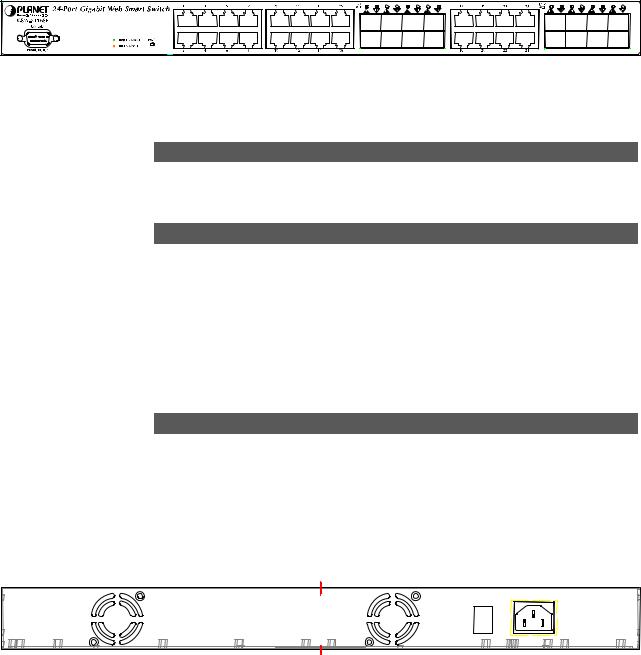
This product provides both Copper and Fiber connecter at same switch – 24 Ports TP and 16 Ports SFP (shared with Port #9 to 24), and automatically distinguishes the speed of incoming connection.
This section describes the hardware features of GSW-2416SF. For easier management and control of the Switch, familiarize yourself with its display indicators, and ports. Front panel illustrations in this chapter display the unit LED indicators. Before connecting any network device to the GSW-2416SF, read this chapter carefully.
2.1 Front Panel
The Front Panel of the GSW-2416SF Web Smart Ethernet Switch consists of 24x Auto-Sensing 10/100/1000Mbps Ethernet RJ-45 Ports and 16x SFP(Small Form-factor Pluggable) Ports. The LED Indicators are also located on the front panel of the GSW-2416SF. And one console port at Front panel for switch management.
Figure 2-1: GSW-2416SF Switch front panel
2.1.1 LED indicators System
LED |
Color |
Function |
PWR |
Green |
Lights to indicate that the Switch has power. |
|
|
|
Per 10/100/1000Mbps port
|
LED |
Color |
Function |
|
1000 |
|
Lights to indicate that the Switch is successfully connecting to the network at |
|
Green |
1000Mbps. |
|
|
LNK/ACT |
||
|
|
Blinks to indicate the Switch is receiving or sending data. |
|
|
|
|
|
|
|
|
|
|
100 |
|
Lights to indicate that the Switch is successfully connecting to the network at |
|
Amber |
100Mbps. |
|
|
LNK/ACT |
||
|
|
Blinks to indicate the Switch is receiving or sending data. |
|
|
|
|
|
|
|
|
|
Per SFP Interface |
|
||
|
|
|
|
|
LED |
Color |
Function |
|
SFP |
|
Lights to indicate that the Switch is successfully connecting to the network at |
|
Green |
1000Mbps through SFP interface. |
|
|
LNK/ACT |
||
|
|
Blinks to indicate the Switch is receiving or sending data. |
|
|
|
|
|
|
|
|
|
2.2 Rear Panel
The rear panel of the GSW-2416SF indicates an AC inlet power socket, which accepts input power from 100 to 240V AC, 50-60Hz, and 1A max. And one I/O power switch at rear panel for power management.
|
100~240V |
|
ON |
AC |
|
|
||
OFF |
50/60H |
|
POWER |
||
z |
||
|
Figure 2-2: GSW-2416SF Switch rear panel
EM-GSW2416SFv1 |
- 6 - |
Power Notice:
1.The device is a power-required device, it means, it will not work till it is powered. If your networks should active all the time, please consider using UPS (Uninterrupted Power Supply) for your device. It will prevent you from network data loss or network downtime.
2.In some area, installing a surge suppression device may also help to protect your GSW-2416SF from being damaged by unregulated surge or current to the GSW-2416SF.
2.3 Hardware Installation
This part describes how to install your Web Smart Ethernet Switch and make connections to the Switch. Please read the following topics and perform the procedures in the order being presented. To install your Switch on a desktop or shelf, simply completed the following steps.
2.3.1 Desktop Installation
To install a Switch on a desktop or shelf, simply completed the following steps:
Step 1: Attached the rubber feet to the recessed areas on the bottom of the Switch.
Step 2: Place the Switch on a desktop or shelf near an AC power source.
Step 3: Keep enough ventilation space between the Switch and the surrounding objects.
#Notice:
When choosing a location, please keep in mind the environmental restrictions discussed in Chapter 1, Section 4, Specification.
Step 4: Connect your Switch to network devices.
A.Connect one end of a standard network cable to the 10/100/1000 RJ-45 ports on the front of the GSW-2416SF Switch.
B.Connect the other end of the cable to the network devices such as printer servers, workstations or routers…etc.
#Notice:
Connection to the Switch requires UTP Category 5/5e/6 network cabling with RJ-45 tips. For more information, please see the Cabling Specification in Appendix A.
Step 5: Supply power to the Switch.
A.Connect one end of the power cable to the Switch.
B.Connect the power plug of the power cable to a standard wall outlet then power on the Switch.
When the Switch receives power, the Power LED should remain solid Green.
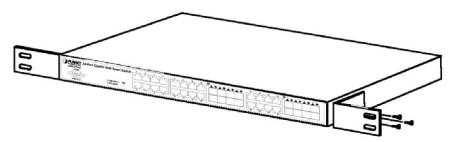
2.3.2 Rack Mounting
To install the Switch in a 19-inch standard rack, follow the instructions described below.
Step 1: Place your Switch on a hard flat surface, with the front panel positioned towards your front side.
Step 2: Attach a rack-mount bracket to each side of the Switch with supplied screws attached to the package. Figure 2-3 shows how to attach brackets to one side of the Switch.
Figure 2-3 Attaching the brackets to the Switch
EM-GSW2416SFv1 |
- 7 - |
Caution:
You must use the screws supplied with the mounting brackets. Damage caused to the parts by using incorrect screws would invalidate your warranty.
Step 3: Secure the brackets tightly.
Step 4: Follow the same steps to attach the second bracket to the opposite side.
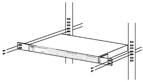
Step 5: After the brackets are attached to the Switch, use suitable screws to securely attach the brackets to the rack, as shown in Figure 2-4.
Figure 2-4 Mounting the Switch in a Rack
Step 6: Proceed with the steps 4 and steps 5 of section 2.3.1 Desktop Installation to connect the network cabling and supply power to your Switch.
EM-GSW2416SFv1 |
- 8 - |
3. SWITCH MANAGEMENT
This chapter describes how to manage the GSW-2416SF. Topics include:
-Overview
-Management methods
-Assigning an IP address to the GSW-2416SF
-Logging on to the GSW-2416SF
3.1 Overview
This chapter gives an overview of switch management. The GSW-2416SF provides a user-friendly, command line under console interface and Simply WEB browser interface. Using these interfaces, you can perform various switch configuration and management activities, including:
zPort configuration
zVLAN Add/Remove/Assign
zFlow Control Enable/Disable
zPort Trunk Create/Assign ( WEB GUI supported )
zSystem IP address setting.
zManagement account and password setting.
zPort status/static monitoring
zSystem reboot and reload factory default.
Please refer to the following Chapter 4 and 5 for the details.
3.2 Management Methods
There are two ways to manage the GSW-2416SF:
-Local Console Management via the Switch serial port.
-Web Management via a network or dial-up connection.
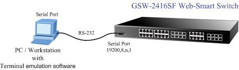
3.2.1 Local Console Management
You can manage the GSW-2416SF locally by connecting a VT100 terminal, or a personal computer or workstation with terminal emulation software, to the Switch serial port. The terminal or workstation connects to the Switch serial port using a null modem cable that has the appropriate connectors on each end.
This management method is ideal when:
-The network is unreliable.
-The Network Manager does not have direct network connection.
The serial port of the Switch default setting is set to 19200 baud using a character format of 8 data bits, no parity, and 1 stop bit.
Therefore, configure the terminal or workstation to use these settings before you log on to the GSW-2416SF. You can change this default setting, if desired, after you log on.
EM-GSW2416SFv1 |
- 9 - |
3.2.2 Web Management
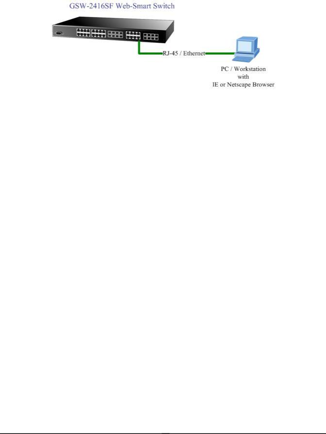
You can manage the GSW-2416SF remotely by having a remote host with web browser, such as Microsoft Internet Explorer or Netscape Navigator.
Using this management method:
The GSW-2416SF must have an Internet Protocol (IP) address accessible for the remote host.
3.3 Assigning an IP Address to the Switch
To manage the GSW-2416SF remotely through the web browser with a Management Station, you must assign an IP address to the GSW-2416SF.
To set the IP address, please use “set ip xxx.xxx.xxx.xxx mmm.mmm.mmm.mmm ggg.ggg.ggg.ggg” command. For example, to configure the switch with the following IP settings:
IP Address: 192.168.0.100
Subnet Mask: 255.255.255.0
Default Gateway: 192.168.0.254
Press the following command and press <Enter>
set ip 192.168.0.100 255.255.255.0 192.168.0.254
If the IP is successfully configured, the switch will apply the new IP address setting immediately. You can access the web interface of GSW-2416SF through the new IP address.
EM-GSW2416SFv1 |
- 10 - |
3.4 Logging on to the GSW-2416SF
When you log on to the GSW-2416SF console port for the first time, a sign-on string appears and you are prompted for a console login user name and password.
The factory default login username is admin without password.
#Notice:
1.For security reason, please change and memorize the new password after this first setup.
2.Only accept command in lowercase letter under console interface.
EM-GSW2416SFv1 |
- 11 - |
4. CONSOLE INTERFACE
4.1 CONNECT TO PC
RS-232 serial cable
Use the bundled RS-232 serial cable and attach the 9-pin female connector to the male connector on the GSW-2416SF. Plug the other side of this cable to your PC.
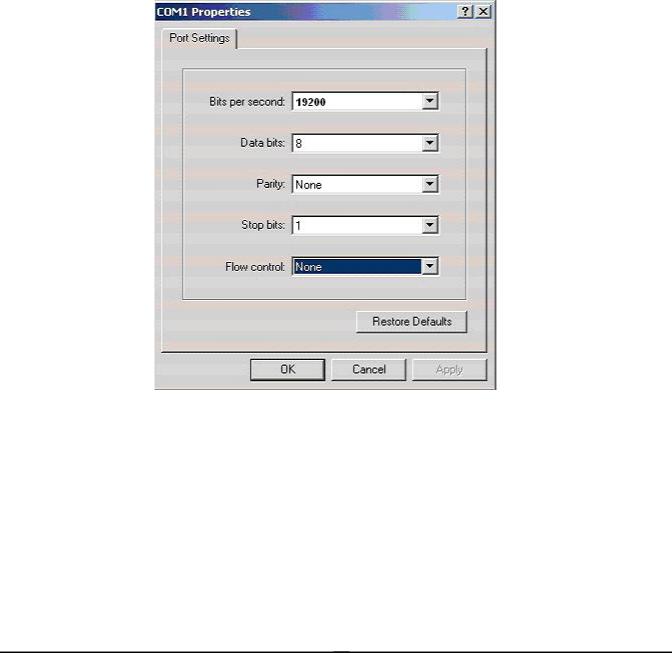
Hyper Terminal
In Windows 98/2000/ME/XP, launch “HyperTerminal”, create a new connection, and adjust settings as below:
Emulation: VT-100 compatible
Baud per second: 19200
Data bits: 8
Parity: None
Stop bits: 1
Flow Control: None
To gain a demo, please see the Figure 4-1.
Figure 4-1 Port Settings for console interface
EM-GSW2416SFv1 |
- 12 - |

4.2 Login in
Login is required to access the console interface after the self-test completes successfully. The factory default user name is "admin" without password. You may change the password by use “set pass” command. Please always enter the correct user name and password. (See Figure 4-2)
Figure 4-2 GSW-2416SF login screen
4.3 Main Menu screen
After login the GSW-2416SF, the main menu screen shows as below.
Figure 4-3 GSW-2416SF Main Menu screen
EM-GSW2416SFv1 |
- 13 - |
4.4 Getting Started
4.4.1 General Guidelines
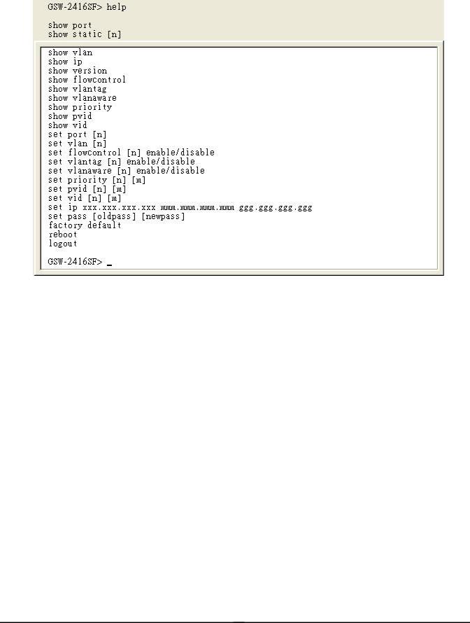
The GSW-2416SF allows users to configure the device via command line under console interface. Please type “help” or “?” for all available commands in the”GSW-2416SF>” prompt. The screen of available commands in Figure 4-4 appears, and the detail description shown in Table 4-1.
|
Figure 4-4 GSW-2416SF available commands screen |
|
|
|
|
Command |
|
Description |
|
|
|
show port |
|
Show all port current status of GSW-2416SF. |
|
|
|
show static [n] |
|
Show per port TX/RX static of GSW-2416SF. |
|
|
|
show vlan |
|
Show current VLAN group status of GSW-2416SF. |
|
|
|
show ip |
|
Show current IP subnet address and default gateway information of |
|
GSW-2416SF. |
|
|
|
|
|
|
|
show version |
|
Show current Software and Hardware versions of GSW-2416SF. |
|
|
|
show flowcontrol |
|
Show current flow control status on each port of GSW-2416SF. |
|
|
|
show vlantag |
|
Show current VLAN Tagged status on each port of GSW-2416SF. |
|
|
|
show vlanaware |
|
Show current VLAN aware status on each port of GSW-2416SF. |
|
|
|
show priority |
|
Show current priority status of GSW-2416SF. |
|
|
|
show pvid |
|
Show current PVID value on each port of GSW-2416SF. |
|
|
|
show vid |
|
Show current VLAN ID of each VLAN Group of GSW-2416SF. |
|
|
|
set port [n] |
|
Set per port auto-negotiation, speed duplex mode, and admin down of |
|
GSW-2416SF. |
|
|
|
|
|
|
|
set vlan [n] |
|
Assign port to specific VALN Group of GSW-2416SF. |
|
|
|
EM-GSW2416SFv1 |
- 14 - |

set flowcontrol [n] |
Enable/Disable the flow control function to specific port [n] of GSW-2416SF. |
|
enable/disable |
||
|
||
|
|
|
set vlantag [n] |
Enable/Disable the VLAN Tagging to specific egress port of GSW-2416SF. |
|
enable/disable |
||
|
||
|
|
|
set vlanaware [n] |
Enable/Disable VLAN-Aware function to specific port of GSW-2416SF. |
|
enable/disable |
||
|
||
|
|
|
set priority [n] [m] |
Allow to configure the priority setting of GSW-2416SF. |
|
|
|
|
set pvid [n] [m] |
Assign PVID on each port of GSW-2416SF. |
|
|
|
|
set vid [n] [m] |
Assign VLAN ID [m] to specific VLAN Group [n] |
|
|
|
|
set IP xxx.xxx.xxx.xxx, |
|
|
mmm. mmm, mmm, mmm, |
Assign IP address, subnet mask, gateway of GSW-2416SF. |
|
ggg.ggg.ggg.ggg |
|
|
|
|
|
set pass [oldpass] |
Change the default password of GSW-2416SF, the maximum length is 8 |
|
[newpass] |
characters. |
|
|
|
|
factory default |
Reset the GSW-2416SF to factory default mode. |
|
|
|
|
reboot |
Reboot the GSW-2416SF. |
|
|
|
|
logout |
Logout console interface of GSW-2416SF. |
|
|
|
Table 4-1 Detail description of GSW-2416SF available commands
#Notice: Only accept command in lowercase letter under console interface.
4.4.2 Show command
From the main menu screen (see Figure 4-3), input “show” and press enter. The show command list screen in Figure 4-5 appears.
Figure 4-5 Show command list screen
This show command list contains eleven items: show port : Please refer to chapter 4.4.2.1. show static [n] : Please refer to chapter 4.4.2.2. show vlan : Please refer to chapter 4.4.2.3. show ip : Please refer to chapter 4.4.2.4.
show version : Please refer to chapter 4.4.2.5.
EM-GSW2416SFv1 |
- 15 - |
show flowcontrol : Please refer to chapter 4.4.2.6. show vlantag : Please refer to chapter 4.4.2.7. show vlanaware : Please refer to chapter 4.4.2.8. show priority : Please refer to chapter 4.4.2.9. show pvid : Please refer to chapter 4.4.2.10. show vid : Please refer to chapter 4.4.2.11.
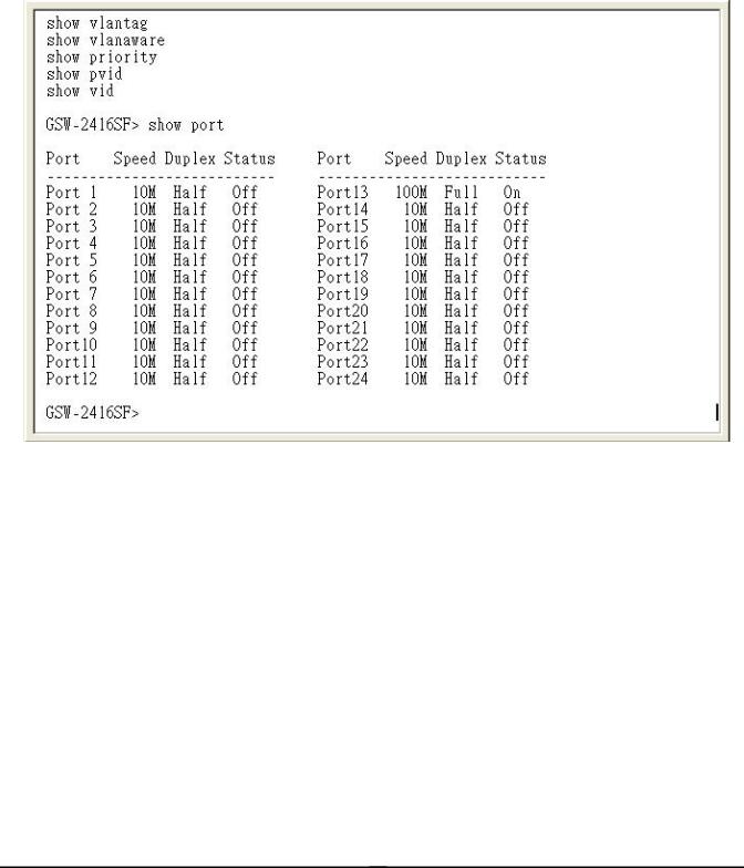
4.4.2.1 Show port
Display the status on each port of GSW-2416SF, this command allows you to view the port status of the Switch and the correct usage is shown as below:
Show port: to view all port status of GSW-2416SF. The screen in Figure 4-6 appears.
Figure 4-6 All port Status screen
4.2.2.2 Show static [n]
Display the traffic static on specific port of GSW-2416SF, the content include the following items :
zTX OK: Number of transmitted packets.
zRX OK: Number of received packets.
zTX Error: Number of transmitted packets with error ( CRC error etc).
zRX Error: Number of received packets with error (CRC error etc).
Show static [n]: n is the Port ID, n=1-24. To view one specific port static of GSW-2416SF, the port static screen in Figure 4-7 appears.
EM-GSW2416SFv1 |
- 16 - |
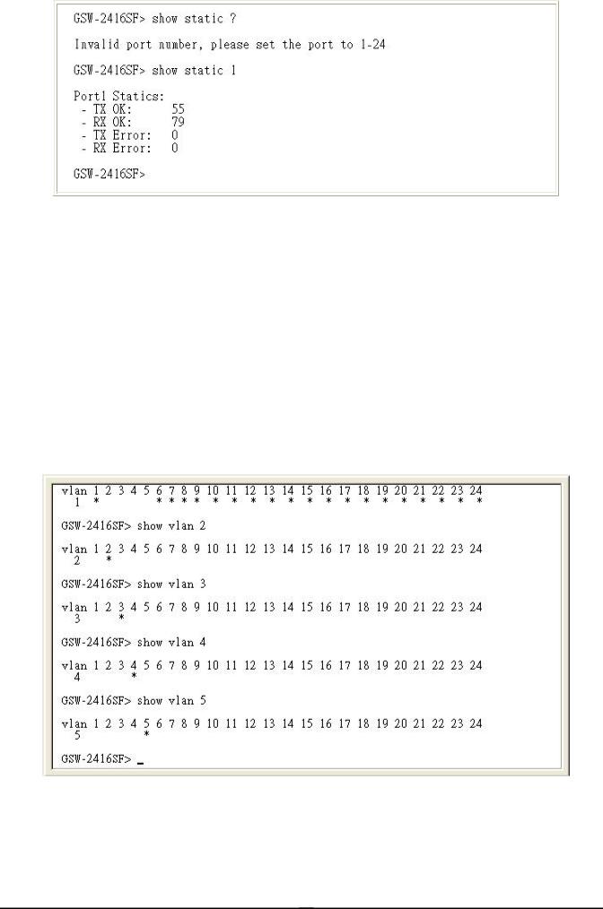
Figure 4-7 Per port static screen
#Notice:
The TX/RX packets counted with error might because:
zPacket with a bad FCS.
zPackets were less than 64 bytes or greater than 1522 bytes.
zPackets were dropped due to lack of resources.
4.4.2.3Show vlan [n]
Display one specific VLAN group status of GSW-2416SF. GSW-2416SF supports up to 24-port based VLAN Groups and the correct usage is shown as below:
Show vlan |
to view all VLAN Group and port member assigned status. |
Show vlan [n] |
n=1-24, to view one specific VLAN Group and port member assigned status. |
|
[n] is the VLAN Group ID. |
The specific VLAN Group status screen in Figure 4-8 appears.
Figure 4-8 VLAN group status screen
EM-GSW2416SFv1 |
- 17 - |
 Loading...