


User's Manual
GSW-1602SF
GSW-2404SF
GSW-2416SF
10/100/1000Mbps 16/24-Port Web Smart Gigabit Ethernet Switch

Trademarks
Copyright © PLANET Technology Corp. 2008. Contents subject to which revision without prior notice.
PLANET is a registered trademark of PLANET Technology Corp. All other trademarks belong to their respective owners.
Disclaimer
PLANET Technology does not warrant that the hardware will work properly in all environments and applications, and makes no warranty and representation, either implied or expressed, with respect to the quality, performance, merchantability, or fitness for a particular purpose.
PLANET has made every effort to ensure that this User's Manual is accurate; PLANET disclaims liability for any inaccuracies or omissions that may have occurred.
Information in this User's Manual is subject to change without notice and does not represent a commitment on the part of PLANET. PLANET assumes no responsibility for any inaccuracies that may be contained in this User's Manual. PLANET makes no commitment to update or keep current the information in this User's Manual, and reserves the right to make improvements to this User's Manual and/or to the products described in this User's Manual, at any time without notice.
If you find information in this manual that is incorrect, misleading, or incomplete, we would appreciate your comments and suggestions.
FCC Warning
This equipment has been tested and found to comply with the limits for a Class A digital device, pursuant to Part 15 of the FCC Rules. These limits are designed to provide reasonable protection against harmful interference when the equipment is operated in a commercial environment. This equipment generates, uses, and can radiate radio frequency energy and, if not installed and used in accordance with the Instruction manual, may cause harmful interference to radio communications. Operation of this equipment in a residential area is likely to cause harmful interference in which case the user will be required to correct the interference at whose own expense.
CE Mark Warning
This is a Class A product. In a domestic environment, this product may cause radio interference, in which case the user may be required to take adequate measures.
WEEE Warning
To avoid the potential effects on the environment and human health as a result of the presence of hazardous substances in electrical and electronic equipment, end users of electrical and electronic equipment should understand the meaning of the crossed-out wheeled bin symbol. Do not dispose of WEEE as unsorted municipal waste and have to collect such WEEE separately.
Revision
PLANET Web Smart Gigabit Ethernet Switch User's Manual
FOR MODELS: GSW-1602SF/GSW-2404SF/GSW-2416SF
REVISION: 1.2 (JANUARY.2008)
Part No.: 2080-A82070-002
-2-
|
TABLE OF CONTENTS |
1. INTRODUCTION............................................................................................................................................................. |
1 |
1.1 PACKAGE CONTENTS .................................................................................................................................................... |
1 |
1.2 HOW TO USE THIS MANUAL ........................................................................................................................................... |
1 |
1.3 PRODUCT FEATURES .................................................................................................................................................... |
1 |
1.4 PRODUCT SPECIFICATION..................................................................................................................................... |
3 |
2. INSTALLATION.............................................................................................................................................................. |
4 |
2.1 PRODUCT DESCRIPTION ................................................................................................................................................ |
4 |
2.1.1 Product Overview................................................................................................................................................ |
4 |
2.1.2 GSW-1602SF/GSW-2404SF/GSW-2416SF Front Panel.................................................................................... |
4 |
2.1.3 LED Indicators..................................................................................................................................................... |
5 |
2.1.4 GSW-1602SF/GSW-2404SF/GSW-2416SF Rear Panel .................................................................................... |
6 |
2.2 INSTALL THE GSW-1602SF/2404SF/2416SF............................................................................................................... |
7 |
2.2.1 Desktop Installation............................................................................................................................................. |
7 |
2.2.2 Rack Mounting .................................................................................................................................................... |
7 |
2.2.3 Installing the SFP transceiver.............................................................................................................................. |
8 |
3. SWITCH MANAGEMENT ............................................................................................................................................ |
10 |
3.1 OVERVIEW ................................................................................................................................................................. |
10 |
3.2 MANAGEMENT METHODS............................................................................................................................................. |
10 |
3.2.1 Web Management............................................................................................................................................. |
10 |
3.2.2 Login the Switch................................................................................................................................................ |
11 |
4. CONFIGURATION........................................................................................................................................................ |
12 |
4.1 MAIN MENU ............................................................................................................................................................... |
12 |
4.2 SYSTEM..................................................................................................................................................................... |
13 |
4.2.1 System Info ....................................................................................................................................................... |
13 |
4.2.2 Misc Configuration ............................................................................................................................................ |
14 |
4.3 PORT CONFIGURATION................................................................................................................................................ |
16 |
4.4 PORT MIRRORING....................................................................................................................................................... |
18 |
4.5 STORM CONTROL ....................................................................................................................................................... |
19 |
4.6 VLANS ..................................................................................................................................................................... |
20 |
4.6.1 VLAN Membership ............................................................................................................................................ |
21 |
4.6.2 Per Port Configuration....................................................................................................................................... |
23 |
4.6.3 VLAN setting example:...................................................................................................................................... |
25 |
4.7 RAPID SPANNING TREE ............................................................................................................................................... |
32 |
4.7.1 RSTP System Configuration ............................................................................................................................. |
33 |
4.7.2 RSTP Port Configuration................................................................................................................................... |
34 |
4.7.3 RSTP Status ..................................................................................................................................................... |
35 |
4.8 LINK AGGREGATION .................................................................................................................................................... |
39 |
4.8.1 Port Trunk ......................................................................................................................................................... |
39 |
4.8.2 LACP................................................................................................................................................................. |
40 |
4.8.3 LACP Status...................................................................................................................................................... |
42 |
4.9 IGMP SNOOPING ....................................................................................................................................................... |
45 |
|
|
|
-3- |

4.9.1 IGMP Snooping Configuration........................................................................................................................... |
45 |
4.9.2 IGMP Snooping Status...................................................................................................................................... |
46 |
4.9.3 Multicast Group Table ....................................................................................................................................... |
48 |
4.10 QUALITY OF SERVICE ................................................................................................................................................ |
49 |
4.10.1 802.1p QoS Mode ........................................................................................................................................... |
50 |
4.10.2 DSCP QoS Mode ............................................................................................................................................ |
52 |
4.11 802.1X MANAGEMENT .............................................................................................................................................. |
53 |
4.11.1 RADIUS Server Configuration......................................................................................................................... |
54 |
4.11.2 Port Access Control ........................................................................................................................................ |
56 |
4.12 FILTER CONFIGURATION ............................................................................................................................................ |
58 |
4.13 MAC ADDRESSES .................................................................................................................................................... |
59 |
4.13.1 Dynamic Address Table .................................................................................................................................. |
59 |
4.13.2 Static MAC Address ........................................................................................................................................ |
60 |
4.14 TOOLS..................................................................................................................................................................... |
61 |
4.14.1 Reboot ............................................................................................................................................................ |
61 |
4.14.2 Factory Reset.................................................................................................................................................. |
61 |
4.14.3 Firmware Upgrade .......................................................................................................................................... |
62 |
4.14.4 Configuration Upload ...................................................................................................................................... |
64 |
4.14.5 Ping................................................................................................................................................................. |
66 |
4.14.6 Cable Diagnostics ........................................................................................................................................... |
67 |
4.14.7 Web Smart Function ....................................................................................................................................... |
69 |
4.15 STATUS ................................................................................................................................................................... |
71 |
4.14.1 Port Statistics .................................................................................................................................................. |
71 |
4.15.2 LACP Status.................................................................................................................................................... |
72 |
4.15.3 RSTP Status ................................................................................................................................................... |
72 |
4.15.4 IGMP Snooping Status.................................................................................................................................... |
72 |
4.15.5 Multicast Group Status.................................................................................................................................... |
72 |
5. SWITCH OPERATION.................................................................................................................................................. |
74 |
5.1 ADDRESS TABLE......................................................................................................................................................... |
74 |
5.2 LEARNING .................................................................................................................................................................. |
74 |
5.3 FORWARDING & FILTERING .......................................................................................................................................... |
74 |
5.4 STORE-AND-FORWARD................................................................................................................................................ |
74 |
5.5 AUTO-NEGOTIATION.................................................................................................................................................... |
74 |
5.6 IGMP SNOOPING ....................................................................................................................................................... |
75 |
6. TROUBLESHOOTING.................................................................................................................................................. |
77 |
APPENDIX A .................................................................................................................................................................... |
78 |
A.1 SWITCH‘S RJ-45 PIN ASSIGNMENTS ............................................................................................................................ |
78 |
A.2 10/100MBPS, 10/100BASE-TX .................................................................................................................................. |
78 |
A.3 RJ-45 CABLE PIN ASSIGNMENT .................................................................................................................................... |
78 |
A.4 AVAILABLE MODULES.................................................................................................................................................. |
79 |
-4-

1. INTRODUCTION
1.1 Package Contents
Check the contents of your package for following parts:
●
●
●
●
●
●
Web Smart Gigabit Ethernet Switch x1
CD-ROM user's manual x1
Quick installation guide x1
19” rack mounting kit x1
Power cord x1
Rubber feet x 4
If any of these are missing or damaged, please contact your dealer immediately, if possible, retain the carton including the original packing material, and use them against to repack the product in case there is a need to return it to us for repair.
1.2 How to Use This Manual
This Web Smart Gigabit Ethernet Switch User Manual is structured as follows:
Section 2, Installation
It explains the functions of GSW-1602SF/GSW-2404SF/GSW-2416SF and how to physically install the GSW-1602SF/GSW-2404SF/GSW-2416SF.
Section 3, Switch Management
It contains information about the managed methods of GSW-1602SF/GSW-2404SF/GSW-2416SF.
Section 4, Configuration
It contains information about the Smart function of GSW-1602SF/GSW-2404SF/GSW-2416SF. Section 5, Switch operation
It contains Switch operation information of GSW-1602SF/GSW-2404SF/GSW-2416SF. Section 6, Troubleshooting
It contains Troubleshoting information of GSW-1602SF/GSW-2404SF/GSW-2416SF.
Appendiex A
It contains cable information of GSW-1602SF/GSW-2404SF/GSW-2416SF.
1.3 Product Features
Generic Features
z Complies with IEEE 802.3, 10Base-T, IEEE 802.3u, 100Base-TX, IEEE 802.3ab,1000Base-T, IEEE 802.3z,1000Base-SX/LX, Ethernet standard
z 16/24-Port 10/100/1000Mbps Gigabit Ethernet ports
z 2/4/16-Port SFP (Small Form-factor Pluggable) for 3.3V mini GBIC module,
-1-

GSW-1602SF - shared with Port-15 and Port-16. GSW-2404SF - shared with Port-21 to Port 24.
GSW-2416SF - shared with Port-1 to Port-8, Port-17 to Port-24
zEach Switching ports support auto-negotiation-10/20Mbps, 100/200Mbps and 1000/2000Mbps supported
zAuto-MDI/MDI-X detection on each RJ-45 port, support CSMA/CD protocol
zPrevents packet loss with back pressure (Half-Duplex) and IEEE 802.3x PAUSE frame flow control (Full-Duplex)
zHigh performance Store and Forward architecture, broadcast storm control, runt/CRC filtering eliminates erroneous packets to optimize the network bandwidth
z8K MAC address table, automatic source address learning and ageing
z32/48Gbps switch fabric, non-blocking switch architecture
z9K Jumbo Frame support at all speed (10/100/1000Mbps)
Layer-2 Switching
zSupport Port-based and IEEE 802.1Q VLAN function, up to 64 VLAN groups
zIEEE 802.1w Rapid-Spanning Tree protocol support
zLink Aggregation support static mode and LACP (IEEE 802.3ad) - up to 8 Trunk groups, each trunk for up to maximum 12 ports
zIGMP Snooping v1/v2 – multicast filtering
Quality of Service
z4 QoS classes per port
zTraffic class assignment based on IEEE 802.1p tag, or DSCP field
zMulticast and Broadcast Storm Control as well as Flooding Control
zRate Limit bandwidth control at both inband and outband in steps of 128kbps
Security
zPort Mirroring support for dedicated port monitoring
zIEEE 802.1X Port-Base access control, RADIUS ServerAuthentication
zSource IP filter per port to block unwanted access
zStatic MAC Address assign destination MAC address at specifies port.
Management
zRemote Web management interface
zFirmware upgrade through Web interface
zCable Diagnostics technology
zSupport SNMPv1 with RFC-1213/1573-Interface group, Ethernet MIB
zSNMP Trap
-2-

1.4 PRODUCT SPECIFICATION
Model |
GSW-1602SF |
|
GSW-2404SF |
|
|
GSW-2416SF |
Hardware Specification |
|
|
|
|
|
|
Network ports |
16 |
|
24 |
|
24 |
|
SFP/mini-GBIC slot |
2 |
|
4 |
|
|
16 |
Switch architecture |
|
Store-and-Forward |
|
|
|
|
Switch Fabric |
32Gbps |
|
|
48Gbps |
||
Switch throughput |
23.8Mpps |
|
35.7Mpps |
|||
Address Table |
|
|
8K entries |
|
|
|
Share data Buffer |
340KB |
|
|
500KB |
||
Flow Control |
Back pressure for half duplex, IEEE 802.3x Pause Frame for full duplex |
|||||
Dimensions (mm) |
440 x 210 x 44 (1U height) |
|
|
440 x 220 x 44 |
||
Weight |
2kg |
|
2kg |
|
|
2.6 kg |
Power Requirement |
100-240V AC, 50-60 Hz |
|||||
Power Consumption |
30 watts, 102BTU |
|
|
60 watts, 190BTU |
||
Standards Conformance |
|
|
|
|
|
|
Network Standards |
IEEE 802.3 (Ethernet), |
|
|
|
|
|
|
IEEE 802.3u (Fast Ethernet) |
|
|
|
|
|
|
IEEE 802.3ab (Gigabit Ethernet) |
|
|
|
||
|
IEEE 802.3z (Gigabit Ethernet, 1000Base-SX/LX) |
|||||
|
IEEE 802.1Q (Tagged VLAN) |
|
|
|
|
|
|
IEEE 802.1w (Rapid Spanning Tree) |
|
|
|
||
|
IEEE 802.1X (Port-Based Authentication) |
|
|
|
||
|
IEEE 802.3ad (Link Aggregation Control Protocol) |
|||||
|
IEEE 802.3x (Full-duplex flow control) |
|
|
|
||
Operating Temperature |
0~50ºC |
|
|
|
|
|
Storage Temperature |
-40~70ºC |
|
|
|
|
|
Operating Humidity |
5% to 90% , relative humidity, non-condensing |
|||||
Storage Humidity |
5% to 90% , relative humidity, non-condensing |
|||||
Regulation Compliance |
FCC Part 15 Class A, CE |
|
|
|
|
|
|
|
|
|
|
|
|
-3-
2. INSTALLATION
This section describes the functionalities of GSW-1602SF/GSW-2404SF/GSW-2416SF’s components and guides how to install it on the desktop or shelf. Basic knowledge of networking is assumed. Please read this chapter completely before continuing.
2.1 Product Description
The PLANET GSW-1602SF/GSW-2404SF/GSW-2416SF is a 16/24-Port 10/100/1000Mbps Web Smart Gigabit Ethernet Switch with non-blocking wire-speed performance. With 32/48Gbps internal switching fabric, the GSW-1602SF/GSW-2404SF/GSW-2416SF can handle extremely large amounts of data transmission in a secure topology linking to a backbone or high-power servers. The GSW-1602SF /GSW-2404SF /GSW-2416SF could recognize up to 8K MAC Address table and provides 340KB /500KB on-chip frame buffer. The GSW-1602SF /GSW-2404SF / GSW-2416SF offers wire-speed packet transfer performance without risk of packet loss. The high data throughput, it can provide the most convenient for user to upgrade their network to Gigabit environment.
2.1.1 Product Overview
PLANET GSW-1602SF/GSW-2404SF/GSW-2416SF is a Web Smart Gigabit Ethernet Switch with 16/24 RJ-45 10/100/1000Mbps ports for high-speed network connectivity. The GSW-1602SF/GSW-2404SF/GSW-2416SF can also automatically identify and determine the correct transmission speed and half/full duplex mode of the attached devices with its 16/24 ports. The Gigabit port can handle large amounts of data transmission in a secure topology linking to a backbone or high-power servers.
These products also supports store-and-forward forwarding scheme to ensure low latency and high data integrity, eliminates unnecessary traffic and relieves congestion on critical network paths. With an intelligent address recognition algorithm, GSW-1602SF/GSW-2404SF/GSW-2416SF could recognize up to 8K different MAC address and enables filtering and forwarding at full wire speed.
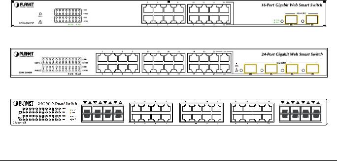
2.1.2 GSW-1602SF/GSW-2404SF/GSW-2416SF Front Panel
Figure 2-1 & 2-2 & 2-3 shows a front panel of GSW-1602SF/GSW-2404SF/GSW-2416SF.
Figure 2-1 PLANET GSW-1602SF Front Panel
Figure 2-2 PLANET GSW-2404SF Front Panel
Figure 2-3 PLANET GSW-2416SF Front Panel
-4-
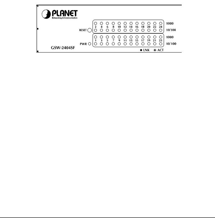
2.1.3LED Indicators
■LED of GSW-1602SF / GSW-2404SF
LED |
Color |
Function |
|
PWR |
Green |
Lights to indicate that the Switch is powered on. |
|
|
|
|
|
1000 |
Green |
Lights to indicate that the Switch is successfully connecting to the network at 1000Mbps. |
|
LNK/ACT |
Blinks to indicate the Switch is receiving or sending data. |
||
|
|||
|
|
|
|
10/100 |
Green |
Lights to indicate that the Switch is successfully connecting to the network at 10/100Mbps. |
|
LNK/ACT |
Blinks to indicate the Switch is receiving or sending data. |
||
|
|||
|
|
|
|
SFP |
|
Lights to indicate that the Switch is successfully connecting to the network at 1000Mbps |
|
Green |
through SFP interface. |
||
LNK/ACT |
|||
|
Blinks to indicate the Switch is receiving or sending data. |
||
|
|
Figure 2-4 PLANET GSW-2404SF LED panel
■LED of GSW-2416SF
¾SFP interfaces
LED |
Color |
Function |
|
SFP |
|
Lights to indicate that the Switch is successfully connecting to the network at 1000Mbps |
|
Orange |
through SFP interface. |
||
LNK/ACT |
|||
|
Blinks to indicate the Switch is receiving or sending data. |
||
|
|
||
|
|
|
¾10/100/1000Base-T Ports
LED |
Color |
Function |
|
1000 |
Green |
Lights to indicate that the Switch is successfully connecting to the network at 1000Mbps. |
|
LNK/ACT |
Blinks to indicate the Switch is receiving or sending data. |
||
|
|||
|
|
||
|
|
|
|
100 |
Green |
Lights to indicate that the Switch is successfully connecting to the network at 100Mbps. |
|
LNK/ACT |
Blinks to indicate the Switch is receiving or sending data. |
||
|
|||
|
|
|
Remark: For port 1 to port 8 and port 17 to port 24, either SFP or TP can be used at one time. SFP will be higher priority
-5-
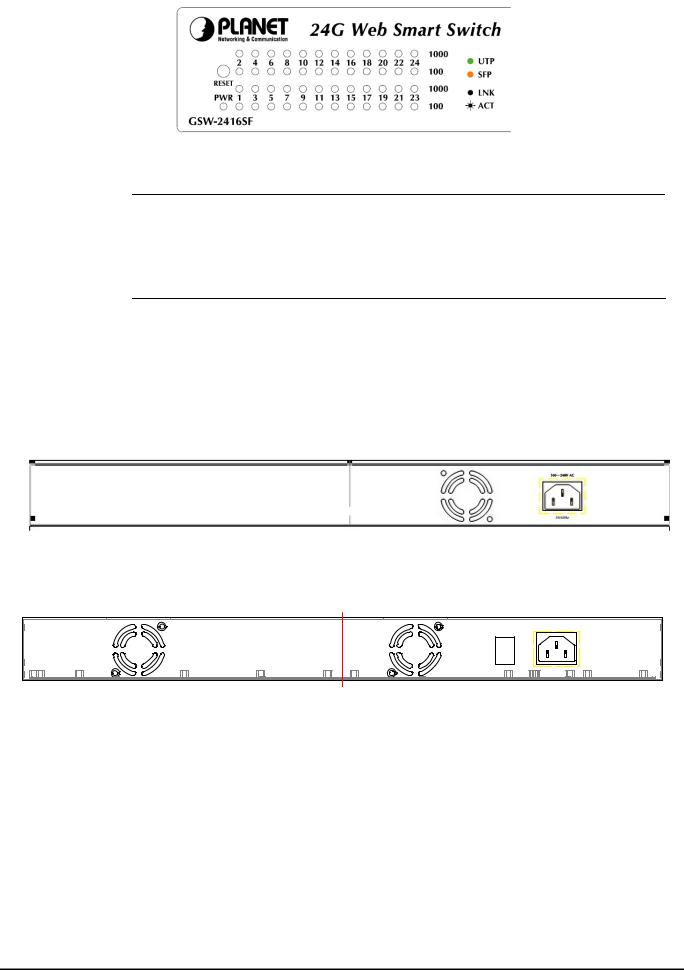
Figure 2-5 PLANET GSW-2416SF LED panel
#Note: To press 5 seconds and release the RESET button. The GSW-1602SF/GSW-2404SF /GSW-2416SF will back to the factory default mode. Be sure that you backup the current configuration of GSW-1602SF/GSW-2404SF/GSW-2416SF; else the entire configuration will be erased when pressing the “RESET” button.
2.1.4 GSW-1602SF/GSW-2404SF/GSW-2416SF Rear Panel
The rear panel of the Switch indicates an AC inlet power socket, which accepts input power from 100 to 240V AC, 50-60Hz.
■GSW-1602SF / GSW-2404SF
Figure 2-6 Rear Panel of GSW-1602SF/GSW-2404SF
■GSW-2416SF
|
100~240V AC |
|
ON |
|
|
OFF |
50/60Hz |
|
POWER |
||
|
Figure 2-7 Rear Panel of GSW-2416SF
Power Notice:
1.The device is a power-required device, it means, it will not work till it is powered. If your networks should active all the time, please consider using UPS (Uninterrupted Power Supply) for your device. It will prevent you from network data loss or network downtime.
2.In some area, installing a surge suppression device may also help to protect your Switch from being damaged by unregulated surge or current to the Switch or the power adapter.
-6-
2.2 Install the GSW-1602SF/2404SF/2416SF
This section describes how to install your GSW-1602SF/GSW-2404SF/GSW-2416SF Web Smart Gigabit Ethernet Switch and make connections to the Switch. Please read the following topics and perform the procedures in the order being presented. PLANET GSW-1602SF/GSW-2404SF/GSW-2416SF Web Smart Gigabit Ethernet Switch do not need software configuration. To install your GSW-1602SF/GSW-2404SF/GSW-2416SF on a desktop or shelf, simply complete the following steps.
2.2.1 Desktop Installation
To install a GSW-1602SF/GSW-2404SF/GSW-2416SF on a desktop or shelf, simply complete the following steps:
Step1: Attach the rubber feet to the recessed areas on the bottom of the Switch.
Step2: Place the GSW-1602SF/GSW-2404SF/GSW-2416SF on a desktop or shelf near an AC power source.
Step3: Keep enough ventilation space between the Switch and the surrounding objects.
# When choosing a location, please keep in mind the environmental restrictions discussed in Chapter Note: 1, Section 4, and Specification.
Step4: Connect your GSW-1602SF/GSW-2404SF/GSW-2416SF to network devices.
A.Connect one end of a standard network cable to the 10/100/1000 RJ-45 ports on the front of the GSW-1602SF/GSW-2404SF/GSW-2416SF
B.Connect the other end of the cable to the network devices such as printer servers, workstations or routers…etc.
#Connection to the Switch requires UTP Category 5 network cabling with RJ-45 tips. For more Note: information, please see the Cabling Specification in Appendix A.
Step5: Supply power to the Switch.
A.Connect one end of the power cable to the GSW-1602SF/GSW-2404SF/GSW-2416SF.
B.Connect the power plug of the power cable to a standard wall outlet.
When the GSW-1602SF/GSW-2404SF/GSW-2416SF receives power, the Power LED should remain solid Green.
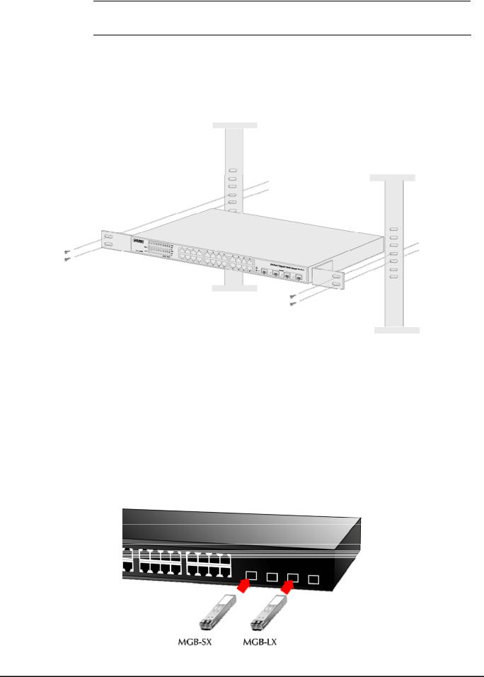
2.2.2 Rack Mounting
To install the switch in a 19-inch standard rack, follow the instructions described below.
Step1: Place your GSW-1602SF/GSW-2404SF/GSW-2416SF on a hard flat surface, with the front panel positioned towards your front side.
Step2: Attach a rack-mount bracket to each side of the Switch with supplied screws attached to the package. Figure 2-8 shows how to attach brackets to one side of the Switch.
Figure 2-8 Attaching the brackets to the Switch
-7-
Caution: You must use the screws supplied with the mounting brackets. Damage caused to the parts by using incorrect screws would invalidate your warranty.
Step3: Secure the brackets tightly.
Step4: Follow the same steps to attach the second bracket to the opposite side.
Step5: After the brackets are attached to the Switch, use suitable screws to securely attach the brackets to the rack, as shown in Figure 2-9
Figure 2-9 Mounting the Switch in a Rack
Step6: Precede with the steps 4 and steps 5 of session 2.2.1 Desktop Installation to connect the network cabling and supply power to your switch.
2.2.3 Installing the SFP transceiver
The sections describe how to insert an SFP transceiver into an SFP slot.
The SFP transceivers are hot-plug e and hot-swappable. You can plug-in and out the transceiver to/from any SFP port without having to power down the Switch. As the Figure 2-10 appears.
Figure 2-10 Plug-in the SFP transceiver
-8-

Approved PLANET SFP Transceivers
PLANET GSW-1602SF/GSW-2404SF/GSW-2416SF support both single mode and multi mode SFP transceiver. The following list of approved PLANET SFP transceivers is correct at the time of publication:
■MGB-SX SFP (1000BASE-SX SFP transceiver )
■MGB-LX SFP (1000BASE-LX SFP transceiver )
# It recommends using PLANET SFPs on the Switch. If you insert a SFP transceiver that is not Note: supported, the Switch will not recognize it.
Before connect the other switches, workstation or Media Converter.
1.Make sure both side of the SFP transfer are with the same media type, for example: 1000Base-SX to 1000Base-SX, 1000Bas-LX to 1000Base-LX.
2.Check the fiber-optic cable type match the SFP transfer model.
¾To connect to 1000Base-SX SFP transceiver, use the multi-mode fiber cablewith one side must be male duplex LC connector type.
¾To connect to 1000Base-LX SFP transceiver, use the single-mode fiber cable-with one side must be male duplex LC connector type.
Connect the fiber cable
1.Attach the duplex LC connector on the network cable into the SFP transceiver.
2.Connect the other end of the cable to a device – switches with SFP installed, fiber NIC on a workstation or a Media Converter..
3.Check the LNK/ACT LED of the SFP slot on the front of the Switch. Ensure that the SFP transceiver is operating correctly.
4.Check the Link mode of the SFP port if the link failed. Co works with some fiber-NICs or Media Converters, set the Link mode to “1000 Force” is needed.
-9-

3. SWITCH MANAGEMENT
This chapter describes how to manage the GSW-1602SF/GSW-2404SF/GSW-2416SF. Topics include:
-Overview
-Management methods
-Assigning an IP address to the GSW-1602SF/GSW-2404SF/GSW-2416SF
-Logging on to the GSW-1602SF/GSW-2404SF/GSW-2416SF
3.1 Overview
This chapter gives an overview of switch management. The GSW-1602SF/GSW-2404SF/GSW-2416SF provides a simply
Web browser interface. Using this interface, you can perform various switch configuration and management activities,
including:
System
Port Configuration
Port Mirroring
Storm Control
VLANs
Rapid Spanning Tree
Link Aggregation
IGMP Snooping
Quality of Service
802.1X Management
Filter Configuration
MAC Address
Tools
Status
Please refer to the following Chapter 4 for more details.
3.2 Management Methods
The way to manage the GSW-1602SF/GSW-2404SF/GSW-2416SF:
- Web Management via a network connection.
3.2.1 Web Management
The PLANET Web-Smart Gigabit Ethernet Switch provides a built-in browser interface. You can manage the GSW-1602SF/GSW-2404SF/GSW-2416SF remotely by having a remote host with web browser, such as Microsoft Internet Explorer, Netscape Navigator or Mozilla Firefox.
-10-
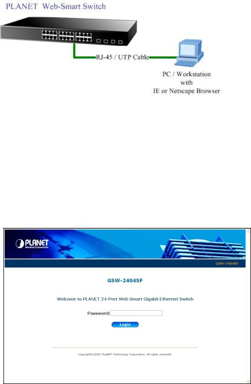
Using this management method:
The GSW-1602SF/GSW-2404SF/GSW-2416SF must have an Internet Protocol (IP) address accessible for the remote host. The screen in Figure 3-1 appears.
Figure 3-1 Web Management via ethernet
3.2.2 Login the Switch
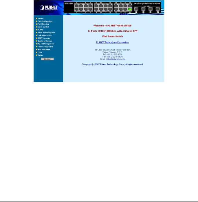
Before you start configure the GSW-1602SF/GSW-2404SF/GSW-2416SF, please note the GSW-1602SF/GSW-2404SF/GSW-2416SF is configured through an Ethernet connection, make sure the manager PC must be set on same the IP subnet address. For example, the default IP address of the GSW-1602SF/GSW-2404SF/GSW-2416SF is 192.168.0.100, then the manager PC should be set at 192.168.0.x (where x is a number between 2 and 254, except 100), and the default subnet mask is 255.255.255.0. Use Internet Explorer 5.0 or above Web browser. Enter IP address http://192.168.0.100 (the factory-default IP address) to access the Web interface.
When the following login screen appears, please enter the default password "admin" screen of GSW-1602SF/GSW-2404SF/GSW-2416SF. The login screen in Figure 3-2
and press Login to enter the main appears.
|
|
Figure 3-2 Login screen |
|
#Note: |
1. |
For security reason, please change and memorize the new password after this first setup. |
|
|
2. |
Only accept command in lowercase letter under Web interface. |
|
|
|
|
|
|
|
|
|
|
|
-11- |
|
4. CONFIGURATION
The GSW-1602SF/GSW-2404SF/GSW-2416SF Web Smart Gigabit Ethernet Switch provide Web interface for Switch smart function configuration and make the Switch operate more effectively - They can be configured through the Web Browser. A network administrator can manage and monitor the GSW-1602SF /GSW-2404SF/GSW-2416SF from the local LAN. This section indicates how to configure the Switch to enable its smart function.
#Notice:
The following section will base on the console screens of GSW-2404SF, for GSW-1602SF and GSW-2416SF the display will be the same to GSW-2404SF.
4.1 Main Menu
After a successful login, the main screen appears, the main screen displays the Switch status. The screen in Figure 4-1 appears.
Figure 4-1 Web Main screen
As listed at the left of the main screen, the configurable smart functions are shown as below:
System – Check the hardware, software version and System MAC address. Setting the IP address and SNMP management for the switch. Explain in section 4.2
Port Configuration – Setup per port Speed/Duplex mode, Flow Control and jumbo frame. Explain in section 4.3
Port Mirroring – dedicated port monitoring for incoming packets. Explain in section 4.4
Storm Control – various type of storm control value assign. Explain in section 4.5
VLANs – Configure VLAN Member / Port Configuration. Explain in section 4.6
Rapid Spanning Tree – Configure Rapid spanning tree topography for any arrangement of bridges . Explain in section 4.7
Link Aggregation – Port Trunk / LACP. Explain in section 4.8
IGMP Snooping – Enables or disables IGMP Snooping on the device to filter the multicast stream. Explain in section 4.9
Quality of Service – Mapping the packet level to classify the packets priority. Explain in section 4.10
802.1X Management – Specify ports with network access control. Explain in section 4.11
Filter Configuration – per port traffic filter based on IP address. Explain in section 4.12
-12-
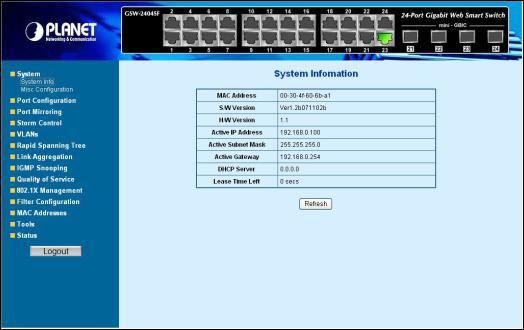
MAC Address – Dynamic Address Table / Static MAC Address. Explain in section 4.13
Tools – Reboot / Factory Reset / Firmware Update / Configuration Upload / Ping / Cable Diagnostic. Explain in section 4.14
Status – Port Statistics Overview / Port Statistics Detail / LACP Status / RSTP Status / IGMP Snooping Status / Multicast Group Status. Explain in section 4.15
4.2System
4.2.1 System Info
The System Info page provides information for the current device information. System Info page helps a switch manager to identify the versions and IP subnet Address etc. The screen in Figure 4-2 appears.
|
|
|
Figure 4-2 System Information screen |
|
The page includes the following fields; see the table 4-1 description of the system information. |
|
|||
|
|
|
|
|
|
• Item |
|
Description |
|
|
|
|
|
|
|
• MAC Address |
|
Specifies the device MAC address. |
|
|
|
|
|
|
|
• S/W Version |
|
The current software version running on the device. |
|
|
|
|
|
|
|
• H/W Version |
|
The current hardware version of the device |
|
|
|
|
|
|
|
• Active IP Address |
|
The current IP Address of the device. The IP Address could be manual assigned |
|
|
|
|
or get via DHCP server. |
|
|
• Active Subnet Mask |
|
The current IP Subnet Mask setting on the device. |
|
|
|
|
|
|
|
• Active Gateway |
|
The current Gateway of the device. |
|
|
• DHCP Server |
|
If the IP address is got and assigned via a DHCP server, the field shows the IP |
|
|
|
|
Address of the DHCP server. |
|
|
• Lease Time left |
|
If the IP address of the device be assigned via a DHCP Server, a DHCP lease |
|
|
|
|
time would be apply to the device too. The lease time left shows the left time if the |
|
|
|
|
device didn’t request the IP Address to the DHCP server, then the IP address will |
|
|
|
|
be released. |
|
|
|
Table 4-1 Description of the system information |
|
|
|
|
|
|
|
|
|
-13- |
|
|
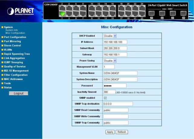
4.2.2 Misc Configuration
The Misc Configuration includes the DHCP Enabled, IP Subnet address, Power Saving and Management VLAN. System name and description, password, Inactivity Timeout and SNMP enable and SNMP related function. The screen in Figure 4-3 appears.
Figure 4-3 Misc Configuration screen
The page includes the following configurable data; see the table 4-2 description of the Misc Configuration.
|
Item |
Description |
|
|
|
|
|
|
DHCP Enabled - |
Choose what the switch should do following power-up: transmit a DHCP request, |
|
|
|
or manual setting (Disable). The factory default is “Disable”. |
|
|
|
|
|
|
IP Address - |
The IP address of the interface. The factory default value is 192.168.0.100 |
|
|
|
|
|
|
Subnet Mask - |
The IP subnet mask for the interface. The factory default value is 255.255.255.0 |
|
|
|
|
|
|
Gateway - |
The default gateway for the IP interface. The factory default value is |
|
|
|
192.168.0.254 |
|
|
|
|
|
|
Power Saving |
This function provide the device can operate under less power consumption |
|
|
|
mode and saves energy, money, and helps protect the environment. The |
|
|
|
available options are disable and enable, the default value is “Disable” |
|
|
|
|
|
|
Management VLAN - |
Specifies the management VLAN ID of the switch. It may be configured to any |
|
|
|
value in the range of 1 - 4093. The management VLAN is used for management |
|
|
|
of the Switch. |
|
|
|
|
|
|
System Name – |
Defines the user-defined device name |
|
|
|
|
|
|
|
|
|
|
|
-14- |
|

System Description |
|
Defines the user-defined device description |
|
|
|
Password - |
|
This function provides administrator to secure Web login |
|
|
|
Inactivity Timeout – |
|
Specifies a time period for the user login. The web interface will be auto logout if |
|
|
there’re no actions from the login user. |
|
|
The default value is 300 seconds; 0 means no inactivity time limit. |
|
|
|
SNMP Enable – |
|
Enable or Disable the SNMP function of the device. While set to enable, the |
|
|
manager could remotely get the interface status and received the traps |
|
|
information. |
|
|
|
SNMP Trap |
|
The Trap function enables the Switch to monitor the Trap through the Web Switch |
destination – |
|
Utility, set the Trap IP Address of the manager workstation where the trap to be |
|
|
sent |
|
|
|
SNMP Read |
|
Functions as a password and used to authenticate the access right of the device. |
Community – |
|
The Read Community is restricted to read-only, for all MIBs except the |
|
|
community table, for which there is no access. |
|
|
|
SNMP write |
|
Functions as a password and used to authenticate the access right of the device. |
Community – |
|
The Write Community accesses the device both read and write - configure to the |
|
|
device via SNMP. |
|
|
|
SNMP Trap |
|
Identifies the community string of the trap manager |
Community – |
|
|
|
|
|
|
Table 4-2 Description of the Misc Configuration |
|
# After change the default password, if you forget the password. Please press 5 seconds and release Note: the “Reset” button in the front panel of GSW-1602SF/GSW-2404SF/GSW-2416SF, the current setting includes VLAN, will be lost and the GSW-1602SF/GSW-2404SF/GSW-2416SF will restore to
the default mode.
-15-
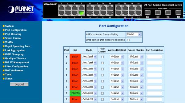
4.3 Port Configuration
This function allows displaying each port’s status. The Link Status in the screen displays the current connection speed and duplex mode; else this function will show down when the port is disconnected. Press the “Refresh” button to renew the screen. The screen in Figure 4-4 appears.
Figure 4-4 Port Configuration screen
The page includes the following configurable data; see the table 4-3 description of the Port Configuration.
|
• Item |
Description |
|
|
|
|
|
|
|
|
• All Ports Jumbo |
The maximum Ethernet frame size the interface supports or is configured, |
|
|
|
Frames Setting |
including Ethernet header, CRC, and payload. Draw the menu bar to select the |
|
|
|
|
mode. |
|
|
|
|
• Disable - The default maximum frame size is 1518 |
|
|
|
|
• 4096 Kbytes – Set the maximum frame size to 4096 Bytes |
|
|
|
|
• 9600 Kbytes - Set the maximum frame size to 9600 Bytes |
|
|
|
• Drop frames after |
Enable or Disable the device to drop frames once the excessive collisions be |
|
|
|
excessive collisions |
detected. |
|
|
|
|
|
|
|
|
• Port |
Indicate port 1 to port 24. |
|
|
|
|
|
|
|
|
• Link |
Indicate current link status and link speed duplex mode of each port. |
|
|
|
|
|
|
|
|
• Mode |
Allow configuring the port speed and operation mode. Draw the menu bar to |
|
|
|
|
select the mode. |
|
|
|
|
• Auto Speed - Setup Auto negotiation. |
|
|
|
|
• 10 half |
- Force sets 10Mbps/Half-Duplex mode. |
|
|
|
• 10 Full |
- Force sets 10Mbps/Full-Duplex mode. |
|
|
|
• 100 half |
- Force sets 100Mbps/Half-Duplex mode. |
|
|
|
• 100 full |
- Force sets 100Mbps/Full-Duplex mode. |
|
|
|
• 1000 full |
- Force sets 10000Mbps/Full-Duplex mode. |
|
|
|
• Disable |
- Shutdown the port manually. |
|
|
|
|
|
|
|
• Flow Control |
Allow Enable or Disable flow control for selected port. |
|
|
|
|
• Enable – 802.3x flow control is enabled on Full-Duplex mode or |
|
|
|
|
|
|
|
|
|
|
-16- |
|
|
|
Backpressure is enabled on Half-Duplex mode. |
|
|
• Disable – No flow control or backpressure function on no matter |
|
|
Full-Duplex or Half-Duplex mode |
• Ingress Rate Limit |
|
The value of inbound traffic limitation in kilobit-per-second (kbps). Per port in step |
|
|
of 128 kbps. |
|
|
Default : No Limit |
|
|
The range between 128 Kbps to 3968 kbps. |
|
|
|
• Egress Shaping |
|
The value of outbound traffic limitation in kilobit-per-second (kbps). Per port in |
|
|
step of 128 kbps. |
|
|
Default : No Limit |
|
|
The range between 128 Kbps to 3968 kbps. |
|
|
|
• Port Description |
|
Make a brief description for the port to help network manager identify the device |
|
|
connected to it. |
|
|
Maximum Length : 8 characters |
|
|
For example, label it as “VoIP Phone” if an VoIP Phone is connected to this port. |
|
|
|
|
Table 4-3 Description of the Port Configuration |
|
#Note: When set each port to run at 100M Full, 100M Half, 10M Full, and 10M Half-speed modes. The Auto-MDIX function will disable.
-17-
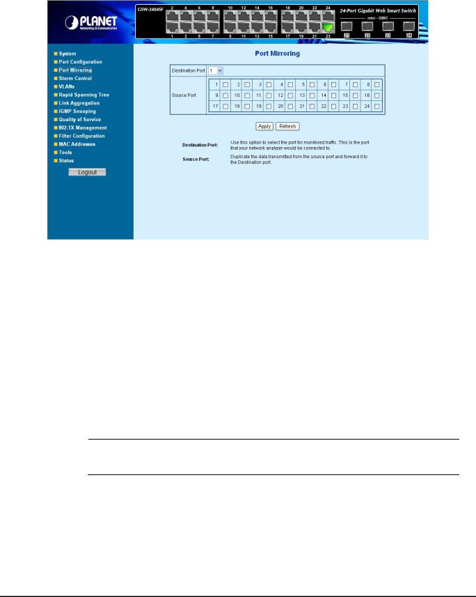
4.4 Port Mirroring
This function provide to monitoring network traffic that forwards a copy of each incoming or outgoing packet from one port of a network Switch to another port where the packet can be studied. It enables the manager to keep close track of switch performance and alter it if necessary. The Port Mirroring screen in Figure 4-5 appears.
|
|
Figure 4-5 Mirror Setting screen |
The page includes the following configurable data table 4-4 description of the Port Mirroring. |
||
|
|
|
|
• Item |
Description |
|
|
|
|
• Destination Port |
Use this option to select the port for monitored traffic. This is the port that your |
|
|
network analyzer would be connected to – such as NAI Sniffer Pro or Ethereal. |
|
• Source Port |
Duplicate the data transmitted from the source port and forward it to the |
|
|
Destination port. |
|
|
Table 4-4 Description of the Port Mirroring |
Configuring the port mirroring by assigning a source port from which to copy all packets and a destination port where those packets will be sent.
#Note: With the Chipset specification – the GSW-1602SF/GSW-2404SF/GSW-2416SF port mirroring support RX (receive) mode only - this mode will duplicate the data that send to the source and forward to the destination port.
-18-
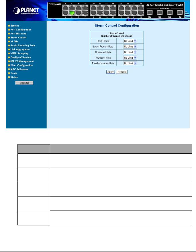
4.5 Storm Control
This function provide various type of storm control of the device, such as ICMP Rate , Learn Frames Rate, Broadcast Rate, Multicast Rate and Flooded unicast Rate. The Storm Control screen in Figure 4-6 appears.
Figure 4-6 Storm Control screen
The page includes the following configurable data table 4-5 description of the Storm Control.
•Item
•ICMP Rate
•Learn Frames Rate
•Broadcast Rate
•Multicast Rate
•Flooded unicast Rate
Description
This function allows to filter the ICMP storm traffic, the available options are 1K/2K/4K/8K/16K/32K/64K/128K/256K/512K/1024K/2048K/4096K/8192K/1638K4/32768K and “No Limit” .
This function allows to filter the learn frames storm traffic, the available options are 1K/2K/4K/8K/16K/32K/64K/128K/256K/512K/1024K/2048K/4096K/8192K/1638K4/32768K and “No Limit” .
This function allows to filter the broadcast storm traffic, the available options are 1K/2K/4K/8K/16K/32K/64K/128K/256K/512K/1024K/2048K/4096K/8192K/1638K4/32768K and “No Limit” .
This function allows to filter the multicast storm traffic, the available options are 1K/2K/4K/8K/16K/32K/64K/128K/256K/512K/1024K/2048K/4096K/8192K/1638K4/32768K and “No Limit” .
This function allows to filter the flooded unicast storm traffic, the available options are 1K/2K/4K/8K/16K/32K/64K/128K/256K/512K/1024K/2048K/4096K/8192K/1638K4/32768K and “No Limit” .
Table 4-5 Description of the Storm Control
-19-

4.6 VLANs
A Virtual LAN (VLAN) is a logical network grouping that limits the broadcast domain. It allows you to isolate network traffic so only members of the VLAN receive traffic from the same VLAN members. Basically, creating a VLAN from a switch is logically equivalent of reconnecting a group of network devices to another Layer 2 switch. However, all the network devices are still plug into the same switch physically.
The GSW-1602SF/GSW-2404SF/GSW-2416SF switch supports IEEE 802.1Q (tagged-based) and Port-Base VLAN setting in web management page. In the default configuration, VLAN support is “802.1Q”.
Port-based VLAN
Port-based VLAN limit traffic that flows into and out of switch ports. Thus, all devices connected to a port are members of the VLAN(s) the port belongs to, whether there is a single computer directly connected to a switch, or an entire department.
On port-based VLAN.NIC do not need to be able to identify 802.1Q tags in packet headers. NIC send and receive normal Ethernet packets. If the packet's destination lies on the same segment, communications take place using normal Ethernet protocols. Even though this is always the case, when the destination for a packet lies on another switch port, VLAN considerations come into play to decide if the packet is dropped by the Switch or delivered.
IEEE 802.1Q VLANs
IEEE 802.1Q (tagged) VLAN are implemented on the Switch. 802.1Q VLAN require tagging, which enables them to span the entire network (assuming all switches on the network are IEEE 802.1Q-compliant).
VLAN allow a network to be segmented in order to reduce the size of broadcast domains. All packets entering a VLAN will only be forwarded to the stations (over IEEE 802.1Q enabled switches) that are members of that VLAN, and this includes broadcast, multicast and unicast packets from unknown sources.
VLAN can also provide a level of security to your network. IEEE 802.1Q VLAN will only deliver packets between stations that are members of the VLAN. Any port can be configured as either tagging or untagging. The untagging feature of IEEE 802.1Q VLAN allows VLAN to work with legacy switches that don't recognize VLAN tags in packet headers. The tagging feature allows VLAN to span multiple 802.1Q-compliant switches through a single physical connection and allows Spanning Tree to be enabled on all ports and work normally.
Any port can be configured as either tagging or untagging. The untagging feature of IEEE 802.1Q VLAN allow VLAN to work with legacy switches that don’t recognize VLAN tags in packet headers. The tagging feature allows VLAN to span multiple 802.1Q-compliant switches through a single physical connection and allows Spanning Tree to be enabled on all ports and work normally.
-20-
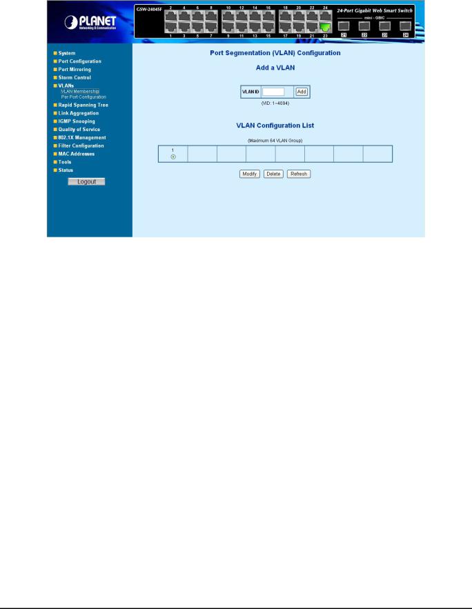
4.6.1 VLAN Membership
This function group individual ports into a small “Virtual” network of their own to be independent of the other ports. The screen in Figure 4-7 appears.
|
|
Figure 4-7 VLAN Membership screen |
The page includes the following items: table 4-6 description of the Add a VLAN. |
||
|
|
|
|
• Item |
Description |
|
• VLAN ID - |
Specify the VLAN Identifier for the new VLAN. (You can only enter data in this |
|
|
field when you are creating a new VLAN.) |
|
|
The range of the VLAN ID is (1 to 4094). |
|
• Add |
To add a new VLAN Group with the specify VLAN ID. Once the Add button be |
|
|
pressed. The page will be redirect to have the VLAN member assign page. |
|
• Modify |
To modify an existence VLAN Groupadds new member ports or remove ports |
|
|
from the selected VLAN Group. |
|
• Delete |
Delete the selected VLAN Group. |
|
• Refresh |
Refresh the VLAN Configuration screen |
|
|
Table 4-6 Description of the Add a VLAN |
4.6.1.1 Add a VLAN Group
The PLANET Web-Smart switch supports up to 64 active VLAN groups and the range for the VLAN ID is 1-4094.
1.To add a VLAN group, filed in the VLAN ID (from 1-4094) and please press “Add” button, the new VLAN Setup screen will pop out.
2.Checked the Member box to select the members for the VLAN group.
3.After setup completed, please press “Apply” to take affect.
-21-
 Loading...