


AUDIO/VIDEO
MULTI-CHANNEL RECEIVER
VSX-D409 VSX-D509S
Operating Instructions
Congratulations on buying this fine Pioneer product.
Please read through these operating instructions so you will know how to operate your model properly. After you have finished reading the instructions, put them away in a safe place for future reference.
WARNING: TO PREVENT FIRE OR SHOCK
HAZARD, DO NOT EXPOSE THIS APPLIANCE TO RAIN OR MOISTURE.
THE POWER SWITCH IS SECONDARY CONNECTED AND THEREFORE DOES NOT SEPARATE THE UNIT FROM MAINS POWER IN STANDBY POSITION.
IMPORTANT
The lightning flash with arrowhead symbol, within an equilateral triangle, is intended to alert the user to the presence of uninsulated "dangerous voltage" within the product's enclosure that may be of sufficient magnitude to constitute a risk of electric shock to persons.
CAUTION
RISK OF ELECTRIC SHOCK
DO NOT OPEN
CAUTION:
TO PREVENT THE RISK OF ELECTRIC SHOCK, DO NOT REMOVE COVER (OR BACK). NO USER-SERVICEABLE PARTS INSIDE. REFER SERVICING TO QUALIFIED SERVICE PERSONNEL.
The exclamation point within an equilateral triangle is intended to alert the user to the presence of important operating and maintenance (servicing) instructions in the literature accompanying the appliance.
This equipment has been tested and found to comply with the limits for a Class B digital device, pursuant to Part
15 of the FCC Rules. These limits are designed to provide reasonable protection against harmful interference in a residential installation. This equipment generates, uses, and can radiate radio frequency energy and, if not installed and used in accordance with the instructions, may cause harmful interference to radio communications. However, there is no guarantee that interference will not occur in a particular installation. If this equipment does cause harmful interference to radio or television reception, which can be determined by turning the equipment off and on, the user is encouraged to try to correct the interference by one or more of the following measures:
–Reorient or relocate the receiving antenna.
–Increase the separation between the equipment and receiver.
–Connect the equipment into an outlet on a circuit different from that to which the receiver is connected.
–Consult the dealer or an experienced radio/TV technician for help.
IMPORTANT NOTICE
The serial number for this equipment is located on the base. Please write this serial number on your enclosed warranty card and keep it in a secure area. This is for your security.
[For Canadian model]
This Class B digital apparatus complies with Canadian ICES-003.
[Pour le modèle Canadien]
Cet appareil numérique de la classe B est conforme à la norme NMB-003 du Canada.
[For Canadian model]
CAUTION: TO PREVENT ELECTRIC SHOCK DO NOT USE THIS (POLARIZED) PLUG WITH AN EXTENSION CORD, RECEPTACLE OR OTHER OUTLET UNLESS THE BLADES CAN BE FULLY INSERTED TO PREVENT BLADE EXPOSURE.
ATTENTION: POUR PREVENIR LES CHOCS ELECTRIQUES NE PAS UTILISER CETTE FICHE POLARISEE AVEC UN PROLONGATEUR, UNE PRISE DE COURANT OU UNE AUTRE SORTIE DE COURANT, SAUF SI LES LAMES PEUVENT ETRE INSERESS A FOND SANS EN LAISSER AUCUNE PARTIE A DECOUVERT.
Information to User
Alteration or modifications carried out without appropriate authorization may invalidate the user's right to operate the equipment.
2
IMPORTANT SAFETY INSTRUCTIONS
READ INSTRUCTIONS — All the safety and operating instructions should be read before the product is operated.
RETAIN INSTRUCTIONS —The safety and operatinginstructionsshouldberetained for future reference.
HEED WARNINGS — All warnings on the product and in the operating instructions should be adhered to.
FOLLOW INSTRUCTIONS — All operating and use instructions should be followed.
CLEANING — Unplug this product from the wall outlet before cleaning. The product should be cleaned only with a polishing cloth or a soft dry cloth. Never clean with furniture wax, benzine, insecticides or other volatile liquids since they may corrode the cabinet.
ATTACHMENTS— Do notuse attachments not recommended by the product manufacturer as they may cause hazards.
WATER AND MOISTURE — Do not use this product near water — for example, near a bathtub, wash bowl, kitchen sink, or laundry tub; in a wet basement; or near a swimming pool; and the like.
ACCESSORIES — Do not place this product on an unstable cart, stand, tripod, bracket, or table. The product may fall, causing serious injury to a child or adult, and serious damage to the product. Use only with a cart, stand, tripod, bracket, or table recommended by the manufacturer, or sold with the product. Any mounting of the product should follow the manufacturer’s instructions, and should use a mounting accessory recommended by the manufacturer.
CART — A product and cart combination should be moved with care. Quick stops, excessive force, and uneven surfaces may cause the product and cart combination to overturn.
VENTILATION — Slots and openings in the cabinet are provided for ventilation and to ensure reliable operation of the product and to protect it from overheating, and these openings must not be blocked or covered. The openings should never be blocked by placing the product on a bed, sofa, rug, or other similar surface. This product should not be placed in a built-in installation such as a bookcase or rack unless proper ventilation is provided or the manufacturer’s instructions have been adhered to.
POWER SOURCES — This product should be operated only from the type of power source indicated on the marking label. If you are not sure of the type of power supply to your home, consult your product dealer or local power company.
LOCATION – The appliance should be installed in a stable location.
NONUSE PERIODS – The power cord of the appliance should be unplugged from the outlet when left un-used for a long period of time.
GROUNDING OR POLARIZATION |
OBJECT AND LIQUID ENTRY — Never |
||
÷ If this product is equipped with a |
push objects of any kind into this product |
||
polarized alternating current line plug (a |
through openings as they may touch |
||
plug having one blade wider than the |
dangerous voltage points or short-out |
||
other), it will fit into the outlet only one |
parts that could result in a fire or electric |
||
way. This is a safety feature. If you are |
shock. Never spill liquid of any kind on |
||
unable to insert the plug fully into the |
the product. |
|
|
outlet, try reversing the plug. If the plug |
SERVICING — Do not attempt to service |
||
should still fail to fit, contact your |
this product yourself as opening or |
||
electrician to replace your obsolete |
removing covers may expose you to |
||
outlet. Do not defeat the safety purpose |
dangerous voltage or other hazards. |
||
of the polarized plug. |
Refer all servicing to qualified service |
||
÷ If this product is equipped with a three- |
personnel. |
|
|
wire grounding type plug, a plug having |
DAMAGE REQUIRING SERVICE — Unplug |
||
a third (grounding) pin, it will only fit into |
this product from the wall outlet and |
||
a grounding type power outlet. This is a |
refer servicing to qualified service |
||
safety feature. If you are unable to insert |
personnel under |
the |
following |
the plug into the outlet, contact your |
conditions: |
|
|
electrician to replace your obsolete |
÷ When the power-supply cord or plug is |
||
outlet. Do not defeat the safety purpose |
damaged. |
|
|
of the grounding type plug. |
÷ If liquid has been spilled, or objects |
||
POWER-CORD PROTECTION — Power- |
have fallen into the product. |
||
supply cords should be routed so that |
÷ If the product has been exposed to rain |
||
they are not likely to be walked on or |
or water. |
|
|
pinched by items placed upon or against |
÷ If the product does not operate normally |
||
them,payingparticularattentiontocords |
by following the operating instructions. |
||
at plugs, convenience receptacles, and |
Adjust only those controls that are |
||
the point where they exit from the |
covered by the operating instructions |
||
product. |
as an improper adjustment of other |
||
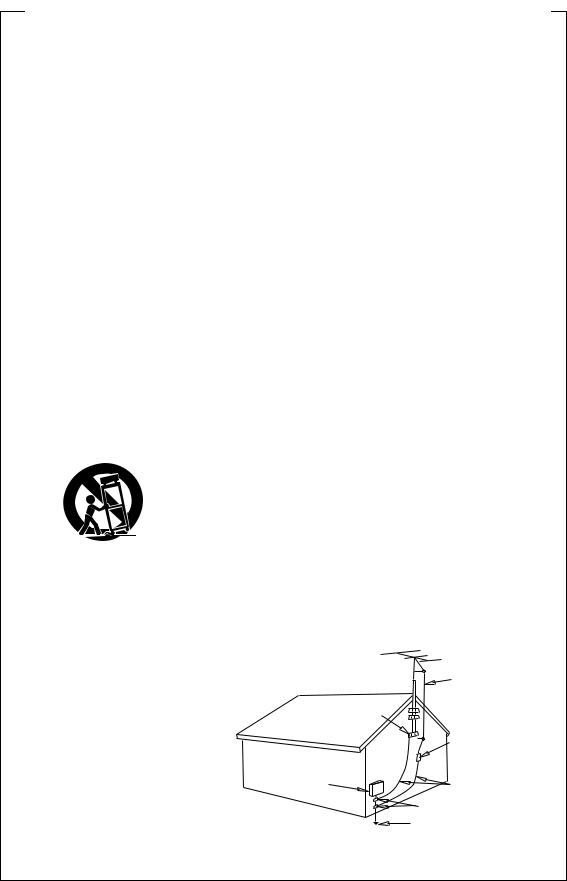
OUTDOOR ANTENNA GROUNDING — If |
controls may result in damage and will |
||
an outside antenna or cable system is |
often require extensive work by a |
||
connected to the product, be sure the |
qualified technician to restore the |
||
antenna or cable system is grounded so |
product to its normal operation. |
||
as to provide some protection against |
÷ If the product has been dropped or |
||
voltage surges and built-up static |
damaged in any way. |
|
|
charges. Article 810 of the National |
÷ When the product exhibits a distinct |
||
ElectricalCode,ANSI/NFPA70,provides |
change in performance — this indicates |
||
information with regard to proper |
a need for service. |
|
|
grounding of the mast and supporting |
REPLACEMENT PARTS |
— When |
|
structure, grounding of the lead-in wire |
replacement parts are required, be sure |
||
to an antenna discharge unit, size of |
the service technician has used |
||
grounding conductors, location of |
replacement parts specified by the |
||
antenna-discharge unit, connection to |
manufacturer or have the same |
||
grounding electrodes, andrequirements |
characteristics as the original part. |
||
for the grounding electrode. See Figure |
Unauthorized substitutions may result |
||
A. |
in fire, electric shock, or other hazards. |
||
LIGHTNING — For added protection for this |
SAFETY CHECK — Upon completion of any |
||
productduringalightningstorm,orwhen |
service or repairs to this product, ask |
||
it is left unattended and unused for long |
the service technician to perform safety |
||
periods of time, unplug it from the wall |
checks to determine that the product is |
||
outlet and disconnect the antenna or |
in proper operating condition. |
||
cable system. This will prevent damage |
WALL OR CEILING MOUNTING — The |
||
to the product due to lightning and |
product should not be mounted to a |
||
power-line surges. |
wall or ceiling. |
|
|
POWER LINES — An outside antenna |
HEAT — The product should be situated |
||
system should not be located in the |
away from heat sources such as |
||
vicinity of overhead power lines or other |
radiators, heat registers, stoves, or other |
||
electric light or power circuits, or where |
products (including |
amplifiers) that |
|
itcanfallintosuchpowerlinesorcircuits. |
produce heat. |
|
|
When installing an outside antenna |
|
|
|
system, extreme care should be taken |
|
|
|
to keep from touching such power lines |
|
|
|
or circuits as contact with them might |
|
|
|
be fatal. |
|
|
|
OVERLOADING — Do not overload wall |
|
|
|
outlets, extension cords, or integral |
|
|
|
convenience receptacles as this can |
|
|
|
result in a risk of fire or electric shock. |
ANTENNA |
|
|
|
|
||
|
LEAD IN |
|
|
|
WIRE |
|
|
GROUND |
|
|
|
CLAMP |
|
|
|
|
ANTENNA |
|
|
|
DISCHARGE UNIT |
||
|
(NEC SECTION 810-20) |
||
ELECTRIC |
GROUNDING CONDUCTORS |
||
SERVICE |
(NEC SECTION 810-21) |
||
EQUIPMENT |
|
|
|
|
GROUND CLAMPS |
|
|
|
POWER SERVICE GROUNDING |
||
Fig. A |
ELECTRODE SYSTEM |
|
|
|
(NEC ART 250, PART H) |
||
NEC — NATIONAL ELECTRICAL CODE
3
Features
DTS* (Digital Theater Systems) decoder equipped 
DTS is a digital sound system introduced in theaters. Playback of DVD, LD, and CD recorded in DTS audio creates the environment of a theater or the sensation of a concert hall in your home.
Dolby** Digital and Dolby Pro Logic
No need to worry about program formats! When playing Dolby Digital or Dolby Surround software in the 2(Dolby) Surround mode, decoding switches automatically according to the input signal. All you have to do is sit back and enjoy! (When connecting a DVD/LD player or LD player using the 2RF output, a commercially available RF demodulator (RFD-1) is required.)
ADVANCED THEATER modes
Four sound modes that enhance DTS and Dolby Surround performance by simulating the environment of a movie theater (DRAMA, ACTION), or the ambience of a concert hall (MUSICAL). With EXPANDED THEATER, you can enjoy Dolby Surround encoded software in simulated Dolby Digital.
Various Surround Effects (DSP)
The DSP (Digital Signal Processing) surround mode allows you to transform your living room into six different sonic environments when listening to music or watching movies.
Midnight Listening Mode
When late night hours or other factors require that the volume be kept low, the surround effects may tend to become less than satisfactory. When the midnight listening mode is on, you can enjoy the effects of quality surround sound even at low volumes.
DVD 5.1 channel input
A special 5.1 Channel input makes the VSX–D409/D509S fully compatible with Dolby Digital decoders and DVD players with 5.1 channel outputs.
The Energy-saving Design
This unit is designed to use minimal electricity when power is switched OFF (in Standby mode). Regarding the value of the power consumption in standby mode, refer to “Specifications” on page 58.
Remote Control of Other Components
The supplied remote control can be used to operate a variety of other components simply by recalling the appropriate preset code. In addition, the multi-operation functions allow you to perform a variety of operations automatically.
* Manufactured under license from Digital Theater Systems, Inc. US Pat. No. 5,451,942 and other worldwide patents issues and pending. “DTS” and “DTS Digital Surround” are trademarks of Digital Theater Systems, Inc. © 1996 Digital Theater Systems, Inc. All
rights reserved.
4
** Manufactured under license from Dolby Laboratories. "Dolby", "Pro Logic" and the double-D symbol are trademarks of Dolby Laboratories. Confidential Unpublished Works. © 1992-1997 Dolby Laboratories, Inc. All rights reserved.

Table of Contents |
|
Features............................................................................... |
4 |
Introductory Information ................................................... |
6 |
Checking the Supplied Accessories .............................................................................. |
6 |
Using this Manual .......................................................................................................... |
6 |
Installing the Receiver ................................................................................................... |
6 |
Preparing the Remote Control ....................................................................................... |
7 |
Connecting Your Equipment ............................................. |
8 |
Connecting Audio Components ..................................................................................... |
8 |
Connecting DVD 5.1 Channel Components .................................................................. |
9 |
AC outlet [switched 100 W (0.8 A) max] ....................................................................... |
9 |
Connecting Video Components ................................................................................... |
10 |
Connecting Digital Components .................................................................................. |
11 |
Connecting Antennas .................................................................................................. |
13 |
Connecting Speakers ................................................................................................... |
14 |
Preparations...................................................................... |
16 |
Setting Up for Surround Sound ................................................................................... |
16 |
Setting the Volume Level of Each Channel ................................................................. |
22 |
Setting Up the Remote Control ................................................................................... |
23 |
Clearing One of the Remote Control Settings (VSX-D509S) ......................................... |
27 |
Clearing All the Remote Control Settings .................................................................... |
27 |
Direct Function ............................................................................................................ |
28 |
Programming a Different Component into the MULTI CONTROL button (VSX-D509S) ....... |
29 |
Checking Preset Code (VSX-D509S) ............................................................................. |
29 |
Displays & Controls.......................................................... |
30 |
Front Panel .................................................................................................................. |
30 |
Display ......................................................................................................................... |
31 |
Remote Control (VSX-D509S) ...................................................................................... |
32 |
Remote Control (VSX-D409) ........................................................................................ |
34 |
Sound Modes ................................................................... |
36 |
Learning about the Sound Modes ............................................................................... |
36 |
Switching ANALOG/DIGITAL Signal Input ................................................................... |
37 |
Playing Sources with Dolby Digital or DTS Sound ....................................................... |
38 |
Selecting a Sound Mode ............................................................................................. |
39 |
Using in MIDNIGHT Listening Mode ........................................................................... |
40 |
ADVANCED THEATER mode ( Dolby/DTS mode) ........................................................ |
41 |
Playing a Source .......................................................................................................... |
41 |
Using the Tuner ................................................................ |
42 |
Finding a Station .......................................................................................................... |
42 |
Tuning Directly to a Station .......................................................................................... |
43 |
Memorizing Stations .................................................................................................... |
43 |
Recalling Memorized Stations ..................................................................................... |
44 |
Making a Recording ......................................................... |
45 |
Making an Audio or a Video Recording ........................................................................ |
45 |
Controlling the Rest of Your System .............................. |
46 |
CD/MD/CD-R/VCR/LD Player Controls ......................................................................... |
46 |
Cassette Deck Controls ............................................................................................... |
47 |
DVD/DVR Player Controls ............................................................................................ |
48 |
DTV Controls ............................................................................................................... |
49 |
Cable TV/Satellite TV/TV Controls ................................................................................ |
50 |
Additional Information..................................................... |
51 |
Troubleshooting ........................................................................................................... |
51 |
Preset Code List (VSX-D509S) ..................................................................................... |
53 |
Preset Code List (VSX-D409) ....................................................................................... |
57 |
Specifications .............................................................................................................. |
58 |
up Set
Operation
5
Introductory Information
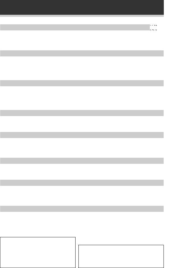
Checking the Supplied Accessories
Please check that you've received the following supplied accessories:
|
FM wire antenna |
AM loop antenna |
VSX-D409: |
|
AA size IEC R6P batteries (x2) |
|
|
|
|
|
SOURCE |
RECEIVER |
|
|
|
|
|
Î |
DVD |
TV |
VCR |
CD-R |
|
|
|
|
|
MULTI CONTROL |
|
|||
MULTI CONTROL |
|
RCV |
CD |
TUN |
TVC |
|||
DVD/LD TV/SAT VCR/DVR CD |
|
|
|
|
|
|||
|
|
CD-R/ |
|
|
1 |
|
2 |
3 |
RECEIVER TUNER |
TAPE/MD TVCONT |
|
MIDNIGHT |
|
5.1CH |
ATT |
||
2 DSPMODE MIDNIGHT 5.1CH |
|
4 |
|
5 |
6 |
|||
|
SIGNAL SELECT |
EFFECT |
||||||
1 |
2 |
3 |
4 |
|
7 |
|
8 |
9 |
CHANNEL |
TEST |
ATT |
SIGNAL |
|
|
|||
SELECT |
TONE |
SELECT |
|
+10 |
|
|
DISC |
|
5 |
6 |
7 |
8 |
|
|
|
0 |
|
CHANNEL |
EFFECT |
|
|
|
ENTER |
|||
LEVEL |
|
TV CONTROL |
|
|||||
9 |
0 |
‡ |
ENTER |
|
|
|
|
|
|
|
10 |
DISC |
|
|
|
TV |
|
|
FUNC |
CH |
|
|
|
|
|
|
|
|
|
|
|
|
|
|
|
VOL |
TV CONTROL |
VOL |
|
TV VOL |
|
TVFUNC MASTERVOLUME |
||
|
FQ |
|
|
|
|
|
|
|
|
|
|
|
|
|
|
MENU |
|
ST |
|
ST |
|
|
|
|
|
|
|
ENTER |
TOP |
|
|
CHANNEL |
|
||
MENU |
|
|
MENU |
|
|
|
|
|
|
FQ |
|
|
|
|
FQ |
|
|
SOUCE |
CLASS |
MPX |
BAND |
|
ST |
|
|
ST |
|
7 |
8 |
3 |
|
|
ENTER |
|
|
D.ACCESS |
|
CHANNEL |
|
|
|
|
|
|
1 |
¡ |
4 |
¢ |
|
|
FQ |
|
|
LOUDNESS FUNCTION |
MUTING |
|
|
8 |
|
|
|
|
|
|
|
|
|
|
|
|
|
RECEIVER |
FL |
REMOTE MASTER |
|
D.ACCESS |
|
BAND |
CLASS |
|
DIMMER |
SETUP |
VOLUME |
|
|
||||
|
|
|
|
|
3 |
|
1 |
¡ |
AUDIO/VIDEOPRE-PROGRAMMED |
|
MPX |
DTV ON / OFF |
DTV MENU |
||||
REMOTECONTROLUNIT |
|
7 |
|
4 |
¢ |
|||
|
|
|
|
|
2 |
DSP |
TEST TONE |
|
|
|
|
|
|
CH SELECT |
CH LEVEL |
FL DIMMER |
|
Using this Manual
LOUDNESS FUNCTION MUTING SETUP
VSX-D509S: |
VSX-D409 |
Î |
AA size IEC LR6 batteries (x2) |
|
AV PRE-PROGRAMMED AND LEARNING |
|
|
REMOTE CONTROL UNIT |
VSX-D509S
Remote control units
This manual is for the VSX-D409/ VSX-D509S audio/video multi-channel receivers.
It is divided into two main sections:
Set up
This section covers installing your receiver and connecting up all the other components in your home theater system to it. It also describes how to set up a multi-channel speaker system to take full advantage of the great surround sound features of your receiver.
Operation
This section shows you how to use every feature of the receiver and its remote control unit. It also covers using the supplied remote control to operate your other home theater components. To find out more about a specific button, control or indicator, see Displays & Controls starting on page 30. This will point you to the relevant chapter in the manual. In the Additional Information section (p.51-58) you'll find a troubleshooting section and specifications.
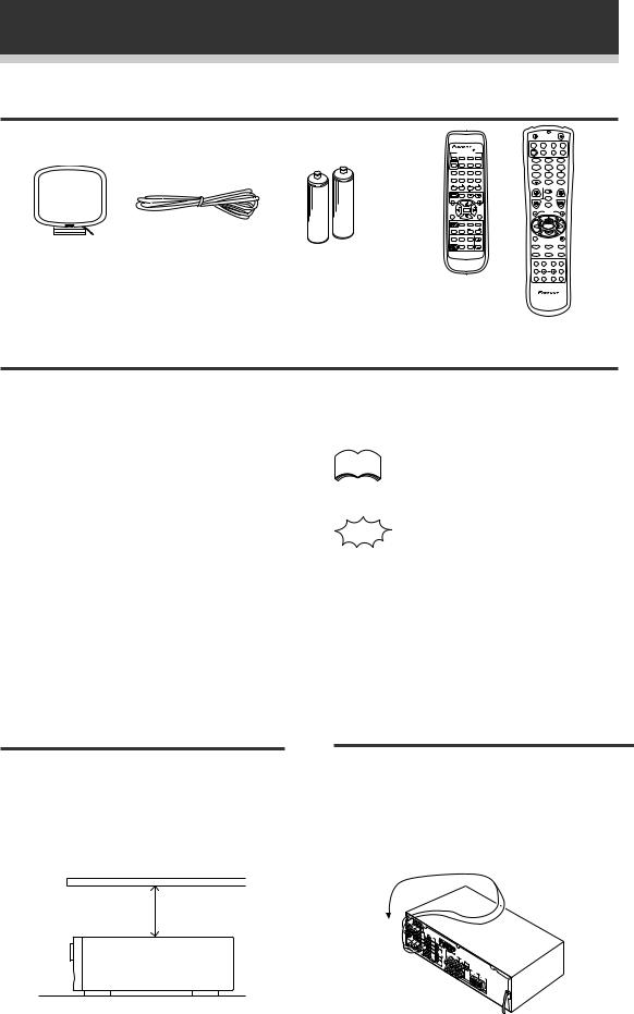
Installing the Receiver
Please note:
•Do not place objects directly on top of this unit. This would prevent proper heat dispersal.
•When installing in a rack, shelf, etc., be sure to leave more than 8 inches of space above the receiver.
The following symbols are used throughout this manual:
memo |
Provides detailed precautions and |
|
advice on operations, etc. |
||
|
Indicates that display is blinking.
When Making Cable
Connections
Be careful not to arrange cables in a manner that bends the cables over the top of this unit as shown in the illustration. If the cables are brought over this unit, the magnetic field produced by the transformers in this unit may cause a humming noise to come from the speakers.
8 inches (20 cm.)
Receiver
6
Introductory Information
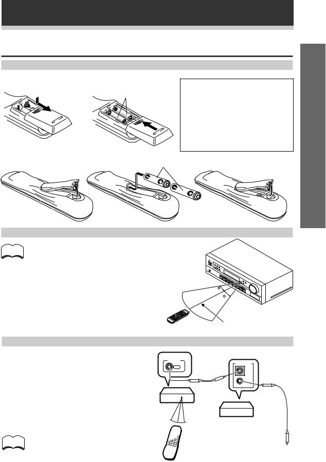
Preparing the Remote Control
Loading the batteries
VSX-D409
Dry cell batteries (AA size IEC R6P × 2)
CAUTION!
Incorrect use of batteries may result in such hazards as leakage and bursting. Observe the following precautions:
¶Never use new and old batteries together.
¶Insert the plus and minus sides of the batteries properly according to the marks in the battery case.
¶Batteries with the same shape may have different voltages. Do not use different batteries together.
VSX-D509S |
Dry cell batteries |
× 2) |
|
(AA size IEC LR6 |
|||
|
up Set
Operating range of remote control unit
memo The remote control may not work properly if:
¶There are obstacles between the remote control and the receiver's remote sensor.
¶Direct sunlight or fluorescent light is shining onto the remote sensor.
¶The receiver is located near a device that is emitting infrared rays.
¶The receiver is operated simultaneously with another infrared remote control unit.
30
30
23ft (7m)
Operating other Pioneer components
By connecting a control cord (optional), you can |
|
control other Pioneer equipment using this remote |
CONTROL |
control unit. Point the remote control unit towards |
OUT |
the remote sensor of this unit, even when operating |
|
other equipment. |
|
The remote control signals are received by the remote sensor of this unit, and sent to the other
devices via the CONTROL OUT terminal. VSX-D409/ VSX-D509S
memo |
You can also control Pioneer components |
|
by pointing the receiver's remote control |
||
|
||
|
directly at the component. This type of |
|
|
operation does not require control cords. |
Remote control unit
CONTROL
IN
OUT
Other Pioneer products with Î mark
Connect to CONTROL IN terminal of other Pioneer products with Î mark.
7
Connecting Your Equipment
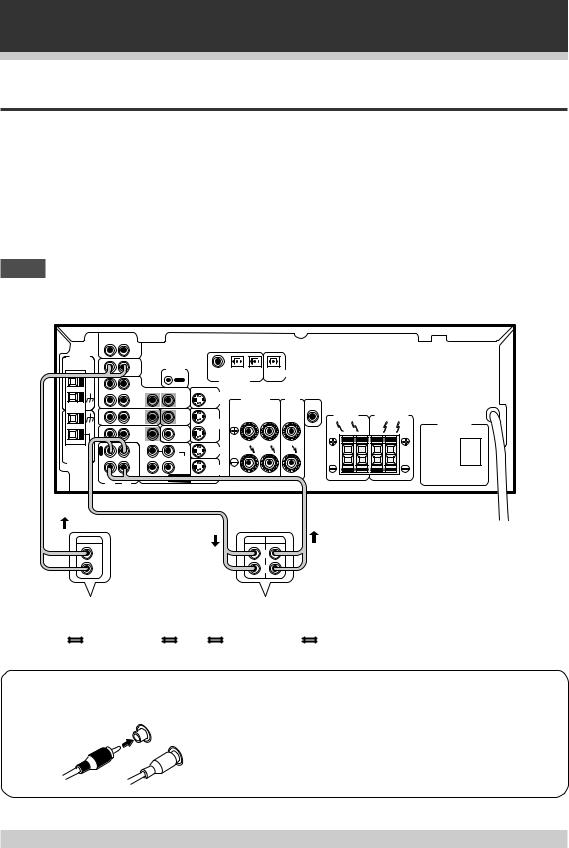
Connecting Audio Components
To begin set up, connect your audio components to the jacks as shown below. These are all analog connections and your analog audio components (cassette deck) use these jacks. Remember that for components you want to record with you need to hook up four plugs (a set of stereo ins and a set of stereo outs), but for components that only play you only need to hook up one set of stereo plugs (two plugs). To use Digital source features you must hook up your digital components to the digital inputs but it is also a good idea to hook up your digital components to analog audio jacks. If you want to record to/from digital components (like an MD) to/from analog components, you must hook up your digital equipment with these analog connections. See p.11-12 for more on digital connections.
When connecting your equipment, always make sure the power is turned off and the power cord is disconnected from the wall outlet.
NOTE
•Only the VSX-D509S has S-video jacks and optical digital out jack.
•The arrows indicate the direction of the audio signal.
AM LOOP |
IN |
|
|
|
|
|
|
|
|
|
|
|
|
|
|
|
AUX |
|
|
|
|
|
|
|
|
|
|
|
|
|
|
ANTENNA |
|
|
|
|
|
|
|
|
|
|
|
|
|
|
|
|
IN |
CD |
|
CONTROL |
|
|
|
|
|
|
|
|
|
|
|
|
|
|
|
COAX |
OPT1 |
OPT2 |
OPT |
DIGITAL |
|
|
|
|
|
||
|
|
|
|
|
|
PCM / 2/ DTS |
|
OUT |
|
|
|
|
|
||
|
O |
|
|
OUT |
|
|
|
|
|
|
|
|
|||
|
|
|
|
DIGITAL IN |
|
|
|
|
|
|
|
|
|||
|
U |
|
|
|
|
|
|
|
|
|
|
|
|
|
|
|
T |
VCR / |
|
|
|
|
|
|
|
|
|
|
|
|
|
|
|
DVR |
|
|
S |
TO |
|
|
A |
|
|
|
|
|
|
|
IN |
|
IN |
OUT |
TVMONTOR |
|
FRONT |
CENTER |
|
|
|
|
|
||
|
|
|
|
|
OUT |
|
SPEAKERS |
SPEAKERS |
CENTER |
|
|
|
|
||
|
|
|
|
|
|
|
|
|
|
|
PREOUT |
|
|
|
|
|
|
TV / |
|
TO |
S |
|
|
R |
L |
|
SURROUND |
|
FRONT |
B |
|
|
IN |
SAT |
IN |
MONTOR |
OUT |
|
|
|
SPEAKERS |
|
SPEAKERS |
||||
|
|
|
|
TV |
|
VCR / |
|
|
|
|
|
|
|
|
|
|
|
|
|
|
S |
DVR |
|
|
|
|
R |
L |
R |
L |
|
|
IN |
DVD |
IN |
SUB |
|
|
|
|
|
|
|||||
|
/ LD |
WOOFER |
IN |
|
|
|
|
|
|
|
|
|
|
||
|
|
|
|
PREOUT |
|
|
|
|
|
|
|
|
|
|
|
FM |
R |
OUT R |
L |
S |
TV / |
|
|
|
|
|
|
|
|
|
|
UNBAL |
E |
IN |
SAT |
|
|
|
|
|
|
|
|
|
|||
75Ω |
C |
CD-R |
|
|
|
|
|
|
|
|
|
|
|
|
|
|
|
SURROUND |
|
|
|
|
|
|
|
|
|
|
|
||
FM |
L |
/TAPE |
|
S |
|
|
|
|
|
|
|
|
|
|
|
ANTENNA |
P |
/MD |
|
|
|
DVD |
|
|
|
|
|
|
|
|
|
|
A |
IN |
|
|
IN |
|
|
|
|
|
|
|
|
|
|
|
Y |
|
|
CENTER |
|
/ LD |
|
|
|
|
|
|
|
|
|
|
|
SUB |
DVD 5.1 CH |
R |
L |
WOOFER |
INPUT |
|
|||
|
|
VSX-D509S
AC OUTLET
OUTPUT |
REC PLAY |
L |
L |
R |
R |
CD player |
|
CD recorder |
|
or Cassette deck |
|
|
|
|
|
|
|
7 Audio cords
Use audio cords (not supplied) to connect the audio components.
R
L
Connect red plugs to R (right) and white plugs to L (left). Be sure to insert completely.
Cassette deck placement
Depending on where the cassette deck is placed, noise may occur during playback of your cassette deck which is caused by leakage flux from the transformer in the receiver. If you experience noise, move the cassette deck farther away from the receiver.
8
Connecting Your Equipment
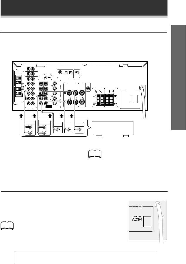
Connecting DVD 5.1 Channel Components
DVD and LD discs are compatible with both 2 channel and 5.1 channel audio output formats. Connections can be made from a DVD player, multi-channel decoder equipped with 5.1 analog outputs to the 5.1 analog inputs on this unit. Always make sure that the receiver is switched off and unplugged from the wall outlet before making or changing any connections.
AM LOOP |
IN |
|
|
|
|
|
|
|
|
|
|
|
|
|
|
|
AUX |
|
|
|
|
|
|
|
|
|
|
|
|
|
|
ANTENNA |
|
|
|
|
|
|
|
|
|
|
|
|
|
|
|
|
IN |
CD |
|
CONTROL |
|
|
|
|
|
|
|
|
|
|
|
|
|
|
|
COAX |
OPT1 |
OPT2 |
OPT |
DIGITAL |
|
|
|
|
|
||
|
|
|
|
|
|
|
|
|
|
||||||
|
|
|
|
|
|
PCM / 2/ DTS |
|
OUT |
|
|
|
|
|
||
|
O |
|
|
OUT |
|
|
|
|
|
|
|
|
|||
|
|
|
|
DIGITAL IN |
|
|
|
|
|
|
|
|
|||
|
U |
|
|
|
|
|
|
|
|
|
|
|
|
|
|
|
T |
VCR / |
|
|
|
|
|
|
|
|
|
|
|
|
|
|
|
DVR |
|
|
S |
TO |
|
|
A |
|
|
|
|
|
|
|
IN |
|
IN |
OUT |
TVMONTOR |
|
FRONT |
CENTER |
|
|
|
|
|
||
|
|
|
|
|
OUT |
|
SPEAKERS |
SPEAKERS |
CENTER |
|
|
|
|
||
|
|
|
|
|
|
|
|
|
|
|
PREOUT |
|
|
|
|
|
|
TV / |
|
TO |
S |
|
|
R |
L |
|
SURROUND |
|
FRONT |
B |
|
|
IN |
SAT |
IN |
MONTOR |
OUT |
|
|
|
SPEAKERS |
|
SPEAKERS |
||||
|
|
|
|
TV |
|
VCR / |
|
|
|
|
|
|
|
|
|
|
|
|
|
|
S |
DVR |
|
|
|
|
R |
L |
R |
L |
|
|
IN |
DVD |
IN |
SUB |
|
|
|
|
|
|
|||||
|
/ LD |
WOOFER |
IN |
|
|
|
|
|
|
|
|
|
|
||
|
|
|
|
PREOUT |
|
|
|
|
|
|
|
|
|
|
|
FM |
R |
OUT R |
L |
S |
TV / |
|
|
|
|
|
|
|
|
|
|
UNBAL |
E |
IN |
SAT |
|
|
|
|
|
|
|
|
|
|||
75Ω |
C |
CD-R |
|
|
|
|
|
|
|
|
|
|
|
|
|
FM |
L |
/TAPE |
|
SURROUND |
S |
|
|
|
|
|
|
|
|
|
|
ANTENNA |
P |
/MD |
|
|
|
DVD |
|
|
|
|
|
|
|
|
|
|
A |
IN |
|
|
IN |
|
|
|
|
|
|
|
|
|
|
|
|
|
CENTER |
/ LD |
|
|
|
|
|
|
|
|
|
||
|
Y |
|
|
|
|
|
|
|
|
|
|
|
|
||
|
|
|
|
|
|
|
|
|
|
|
|
|
|
||
|
|
SUB |
DVD 5.1 CH |
R |
L |
WOOFER |
INPUT |
|
|
VSX-D509S
AC OUTLET
FRONT |
SURROUND |
|
|
|
OUT PUT |
OUT PUT |
SUB |
VIDEO |
Components equipped |
L |
L |
WOOFER CENTER |
OUT |
|
|
|
with 5.1 channel analog |
||
|
|
|
|
|
R |
R |
|
|
output jacks |
up Set
memo
The 5.1 channel input can only be used when DVD 5.1 CH is selected.
AC outlet [switched 100 W (0.8 A) max]
Power supplied through this outlet is turned on and off by the receiver's POWER switch.
Total electrical power consumption of connected equipment should not exceed 100 W (0.8 A).
Do not connect a heater, TV, etc.
|
|
|
memo |
• This unit should be disconnnected by removing the power plug from |
|
|
||
the wall socket when not in regular use, e.g., on vacation. |
|
|
|
|
|
|
• Do not connect appliances with high power consumption such as |
|
|
heaters, irons, or television sets to this AC OUTLET in order to avoid |
|
|
overheating and fire risk. This can also cause the receiver to malfunction. |
|
CAUTION:
DO NOT CONNECT A MONITOR OR TV SET TO THIS UNIT'S AC OUTLET.
9

Connecting Your Equipment
Connecting Video Components
Connect your video components to the jacks as shown below. Regarding digital video components (like a DVD player), you must use the analog connections pictured on this page for the video signal but in order to use Digital source you should hook up their audio to a digital input (see the next page). It is also a good idea to hook up your digital components with analog audio connections as well (see the previous page). To cover all possible laser discs a DVD/LD player or LD player requires an analog connection (as shown here) and two digital connections (see the next page).
When connecting your equipment always make sure the power is turned off and the power cord is disconnected from the wall outlet.
TV tuner
Video deck
(or Satellite tuner)
OUTPUT |
INPUT |
OUTPUT |
VIDEO |
VIDEO |
VIDEO |
L |
L |
L |
R |
R |
R |
VSX-D509S
AM LOOP |
IN |
|
|
|
|
|
|
|
|
|
|
|
|
|
|
|
AUX |
|
|
|
|
|
|
|
|
|
|
|
|
|
|
ANTENNA |
|
|
|
|
|
|
|
|
|
|
|
|
|
|
|
|
IN |
CD |
|
CONTROL |
|
|
|
|
|
|
|
|
|
|
|
|
|
|
|
COAX |
OPT1 |
OPT2 |
OPT |
DIGITAL |
|
|
|
|
|
||
|
|
|
|
|
|
|
|
|
|
||||||
|
|
|
|
|
|
PCM / 2/ DTS |
|
OUT |
|
|
|
|
|
||
|
O |
|
|
OUT |
|
|
|
|
|
|
|
|
|||
|
|
|
|
DIGITAL IN |
|
|
|
|
|
|
|
|
|||
|
U |
|
|
|
|
|
|
|
|
|
|
|
|
|
|
|
T |
VCR / |
|
|
|
|
|
|
|
|
|
|
|
|
|
|
|
DVR |
|
|
S |
TO |
|
|
A |
|
|
|
|
|
|
|
IN |
|
IN |
OUT |
TVMONTOR |
|
FRONT |
CENTER |
|
|
|
|
|
||
|
|
|
|
|
OUT |
|
SPEAKERS |
SPEAKERS |
CENTER |
|
|
|
|
||
|
|
|
|
|
|
|
|
|
|
|
PREOUT |
|
|
|
|
|
|
TV / |
|
TO |
S |
|
|
R |
L |
|
SURROUND |
|
FRONT |
B |
|
|
IN |
SAT |
IN |
MONTOR |
OUT |
|
|
|
SPEAKERS |
|
SPEAKERS |
||||
|
|
|
|
TV |
|
VCR / |
|
|
|
|
|
|
|
|
AC OUTLET |
|
|
|
|
|
S |
DVR |
|
|
|
|
R |
L |
R |
L |
|
|
IN |
DVD |
IN |
SUB |
|
|
|
|
|
|
|||||
|
/ LD |
WOOFER |
IN |
|
|
|
|
|
|
|
|
|
|
||
|
|
|
|
PREOUT |
|
|
|
|
|
|
|
|
|
|
|
FM |
R |
OUT R |
L |
S |
TV / |
|
|
|
|
|
|
|
|
|
|
UNBAL |
E |
IN |
SAT |
|
|
|
|
|
|
|
|
|
|||
75Ω |
C |
CD-R |
|
|
|
|
|
|
|
|
|
|
|
|
|
|
|
SURROUND |
|
|
|
|
|
|
|
|
|
|
|
||
FM |
P |
/TAPE |
|
S |
|
|
|
|
|
|
|
|
|
|
|
ANTENNA |
/MD |
|
|
|
|
|
|
|
|
|
|
|
|
||
|
L |
IN |
|
|
DVD |
|
|
|
|
|
|
|
|
|
|
|
A |
|
|
CENTER |
IN |
/ LD |
|
|
|
|
|
|
|
|
|
|
Y |
|
|
|
|
|
|
|
|
|
|
|
|
||
|
|
|
|
|
|
|
|
|
|
|
|
|
|
||
|
|
SUB |
DVD 5.1 CH |
R |
L |
WOOFER |
INPUT |
|
|
OUTPUT |
INPUT |
VIDEO |
|
L |
VIDEO |
R |
|
7 Front
|
VIDEO INPUT |
|
S-VIDEO |
VIDEO |
L AUDIO R |
Video camera (etc.)
TV DVD player (monitor) (or LD player)
7 Audio/Video cords
Use audio/video cords (not supplied) to connect the video components and a video cord to connect the monitor TV.
R |
|
Connect red |
|
L |
plugs to R (right), |
||
|
|||
|
white plugs to L |
||
|
VIDEO |
||
|
(left), and the |
||
|
|
yellow plugs to |
|
|
|
VIDEO. |
|
|
|
Be sure to insert |
|
|
|
completely. |
VIDEO INPUT
V L R
VSX-D509S only
Front video connections are accessed via the front panel input selector as “VIDEO.”
memo VSX-D509S only
If your video components have S-video jacks, you could use S-video cords (not supplied) to connect them on the back of the receiver.
However, if you use S-video cords for your video hook ups you must also hook up your TV with S- video connections. Conversely, if you use regular composite video cords for video hook ups, you should use them for your TV as well.
10
Connecting Your Equipment
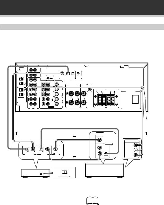
Connecting Digital Components
In order to use PCM/2Digital/DTS soundtracks, you need to make digital audio connections. You can do this by either coaxial or optical connections (you do not need to do both). The quality of these two types of connections is the same but since some digital components only have one type of digital terminal, it is a matter of matching like with like (for example, the coaxial out from the component to coaxial in on the receiver). The VSX-D409/D509S has coaxial and two optical inputs for a total of three digital inputs. Connect your digital components as shown below. There is one digital out jack which is marked PCM/2/DTS (VSX-D509S only) OUT. If you connect this to the optical input on a digital recorder (currently these include MD, DAT and CD-R) you can make direct digital recordings with this unit.
When connecting your equipment, always make sure the power is turned off and the power cord is disconnected from the wall outlet.
VSX-D509S
AM LOOP |
IN |
AUX |
|
|
|
|
|
|
|
|
|
|
VSX-D509S only |
||
ANTENNA |
|
|
|
|
|
|
|
|
|
|
|
|
|
|
|
|
IN |
CD |
|
CONTROL |
|
|
|
|
|
|
|
|
|
|
|
|
|
|
|
COAX |
OPT1 |
OPT2 |
OPT |
DIGITAL |
|
|
|
|
|
||
|
|
|
|
|
|
PCM / 2/ DTS |
|
OUT |
|
|
|
|
|
||
|
O |
|
|
OUT |
|
|
|
|
|
|
|
|
|||
|
|
|
|
DIGITAL IN |
|
|
|
|
|
|
|
|
|||
|
U |
|
|
|
|
|
|
|
|
|
|
|
|
|
|
|
T |
VCR / |
|
|
|
|
|
|
|
|
|
|
|
|
|
|
|
DVR |
|
|
S |
TO |
|
|
A |
|
|
|
|
|
|
|
IN |
|
IN |
OUT |
TVMONTOR |
|
FRONT |
CENTER |
|
|
|
|
|
||
|
|
|
|
|
OUT |
|
SPEAKERS |
SPEAKERS |
CENTER |
|
|
|
|
||
|
|
|
|
|
|
|
|
|
|
|
PREOUT |
|
|
|
|
|
|
TV / |
|
TO |
S |
|
|
R |
L |
|
SURROUND |
|
FRONT |
B |
|
|
IN |
SAT |
IN |
MONTOR |
OUT |
|
|
|
SPEAKERS |
|
SPEAKERS |
||||
|
|
|
|
TV |
|
VCR / |
|
|
|
|
|
|
|
|
AC OUTLET |
|
|
|
|
|
S |
DVR |
|
|
|
|
R |
L |
R |
L |
|
|
IN |
DVD |
IN |
SUB |
|
|
|
|
|
|
|||||
|
/ LD |
WOOFER |
IN |
|
|
|
|
|
|
|
|
|
|
||
|
|
|
|
PREOUT |
|
|
|
|
|
|
|
|
|
|
|
FM |
R |
OUT R |
L |
S |
TV / |
|
|
|
|
|
|
|
|
|
|
UNBAL |
E |
IN |
SAT |
|
|
|
|
|
|
|
|
|
|||
75Ω |
C |
CD-R |
|
|
|
|
|
|
|
|
|
|
|
|
|
|
|
SURROUND |
|
|
|
|
|
|
|
|
|
|
|
||
FM |
P |
/TAPE |
|
S |
|
|
|
|
|
|
|
|
|
|
|
ANTENNA |
/MD |
|
|
|
|
|
|
|
|
|
|
|
|
||
|
L |
IN |
|
|
DVD |
|
|
|
|
|
|
|
|
|
|
|
A |
|
|
CENTER |
IN |
/ LD |
|
|
|
|
|
|
|
|
|
|
Y |
|
|
|
|
|
|
|
|
|
|
|
|
||
|
|
SUB |
DVD 5.1 CH |
R |
L |
WOOFER |
INPUT |
|
|||
|
|
DIGITAL OUT |
DIGITAL |
DIGITAL |
DIGITAL |
|
COAX |
||||
OUT |
OUT |
IN |
||
|
up Set
DVD player |
|
CD player |
|
CD recorder |
|
|
|
|
|
7 Digital audio cords/Optical cables
Commercially available digital audio coaxial cords (standard video cords can also be used) or optical cables (not supplied) are used to connect digital components to this receiver.
When you use optical digital input or output terminals, pull off the caps and insert the plugs. Be sure to insert completely.
Digital audio cord |
Optical cable |
|
|
(or standard video cord) |
|
11
Connecting Your Equipment
Example of connection using a DVD/LD or LD player
When playing LD recorded in Dolby Digital
To connect a DVD/LD or LD player with its 2RF output, a commercially available RF demodulator (RFD-1) is required. The RF demodulator changes the RF signal to a digital signal which is then processed by the VSXD409/D509S models through their digital input jacks. For more details, refer to the instruction manual supplied with the RFD-1.
AM LOOP |
IN |
|
|
|
|
|
|
|
|
|
|
|
|
|
|
|
AUX |
|
|
|
|
|
|
|
|
|
|
|
|
|
|
ANTENNA |
|
|
|
|
|
|
|
|
|
|
|
|
|
|
|
|
IN |
CD |
|
CONTROL |
|
|
|
|
|
|
|
|
|
|
|
|
|
|
|
COAX |
OPT1 |
OPT2 |
OPT |
DIGITAL |
|
|
|
|
|
||
|
|
|
|
|
|
PCM / 2/ DTS |
|
OUT |
|
|
|
|
|
||
|
O |
|
|
OUT |
|
|
|
|
|
|
|
|
|||
|
|
|
|
DIGITAL IN |
|
|
|
|
|
|
|
|
|||
|
U |
|
|
|
|
|
|
|
|
|
|
|
|
|
|
|
T |
VCR / |
|
|
|
|
|
|
|
|
|
|
|
|
|
|
|
DVR |
|
|
S |
TO |
|
|
A |
|
|
|
|
|
|
|
IN |
|
IN |
OUT |
TVMONTOR |
|
FRONT |
CENTER |
|
|
|
|
|
||
|
|
|
|
|
OUT |
|
SPEAKERS |
SPEAKERS |
CENTER |
|
|
|
|
||
|
|
|
|
|
|
|
|
|
|
|
PREOUT |
|
|
|
|
|
|
TV / |
|
TO |
S |
|
|
R |
L |
|
SURROUND |
|
FRONT |
B |
|
|
IN |
SAT |
IN |
MONTOR |
OUT |
|
|
|
SPEAKERS |
|
SPEAKERS |
||||
|
|
|
|
TV |
|
VCR / |
|
|
|
|
|
|
|
|
|
|
|
|
|
|
S |
DVR |
|
|
|
|
R |
L |
R |
L |
|
|
IN |
DVD |
IN |
SUB |
|
|
|
|
|
|
|||||
|
/ LD |
WOOFER |
IN |
|
|
|
|
|
|
|
|
|
|
||
|
|
|
|
PREOUT |
|
|
|
|
|
|
|
|
|
|
|
FM |
R |
OUT R |
L |
S |
TV / |
|
|
|
|
|
|
|
|
|
|
UNBAL |
E |
IN |
SAT |
|
|
|
|
|
|
|
|
|
|||
75Ω |
C |
CD-R |
|
|
|
|
|
|
|
|
|
|
|
|
|
|
|
SURROUND |
|
|
|
|
|
|
|
|
|
|
|
||
FM |
L |
/TAPE |
|
S |
|
|
|
|
|
|
|
|
|
|
|
ANTENNA |
P |
/MD |
|
|
|
DVD |
|
|
|
|
|
|
|
|
|
|
A |
IN |
|
|
IN |
|
|
|
|
|
|
|
|
|
|
|
Y |
|
|
CENTER |
|
/ LD |
|
|
|
|
|
|
|
|
|
|
|
SUB |
DVD 5.1 CH |
|
R |
L |
WOOFER |
||
INPUT |
||||
|
||||
|
|
VSX-D509S
AC OUTLET
PCM/ |
PCM/ |
PCM/ |
PCM/ |
|
|
(OPT.) |
|
(OPT.) |
|
RF IN |
|
DIGITAL OUT |
DIGITAL IN |
||||
(AC-3)(LD) |
|||||
|
|
|
|
||
DIGITAL IN
OPTICAL
 COAXIAL
RF demodulator RFD-1
 RF OUT (AC-3)(LD)
OUTPUT
DIGITAL OUT
PCM (OPT.)
VIDEO
1
L 
2 3
R
DVD/LD player or LD player
Make sure the RF demodulator digital in memo switch is set correctly (optical or coaxial
depending on the connection).
12
Connecting Your Equipment
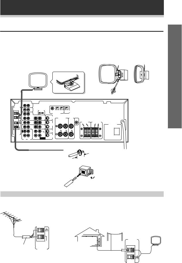
Connecting Antennas
Connect the AM loop antenna and the FM wire antenna as shown below. To improve reception and sound quality, connect external antennas (see Using external antennas, below). Always make sure that the receiver is switched off and unplugged from the wall outlet before making or changing any connections.
AM loop antenna
Assemble the antenna and connect to the receiver. Attach to a wall, etc. (if desired) and face in the direction that gives the best reception.
up Set
VSX-D509S
AM LOOP |
IN |
|
|
|
|
|
|
|
|
|
|
|
|
|
|
|
AUX |
|
|
|
|
|
|
|
|
|
|
|
|
|
|
ANTENNA |
|
|
|
|
|
|
|
|
|
|
|
|
|
|
|
|
IN |
CD |
|
CONTROL |
|
|
|
|
|
|
|
|
|
|
|
|
|
|
|
COAX |
OPT1 |
OPT2 |
OPT |
DIGITAL |
|
|
|
|
|
||
|
|
|
|
|
|
PCM / 2/ DTS |
|
OUT |
|
|
|
|
|
||
|
O |
|
|
OUT |
|
|
|
|
|
|
|
|
|||
|
|
|
|
DIGITAL IN |
|
|
|
|
|
|
|
|
|||
|
U |
|
|
|
|
|
|
|
|
|
|
|
|
|
|
|
T |
VCR / |
|
|
|
|
|
|
|
|
|
|
|
|
|
|
|
DVR |
|
|
S |
TO |
|
|
A |
|
|
|
|
|
|
|
IN |
|
IN |
OUT |
TVMONTOR |
|
FRONT |
CENTER |
|
|
|
|
|
||
|
|
|
|
|
OUT |
|
SPEAKERS |
SPEAKERS |
CENTER |
|
|
|
|
||
|
|
|
|
|
|
|
|
|
|
|
PREOUT |
|
|
|
|
|
|
TV / |
|
TO |
S |
|
|
R |
L |
|
SURROUND |
|
FRONT |
B |
|
|
IN |
SAT |
IN |
MONTOR |
OUT |
|
|
|
SPEAKERS |
|
SPEAKERS |
||||
|
|
|
|
TV |
|
VCR / |
|
|
|
|
|
|
|
|
AC OUTLET |
|
|
|
|
|
S |
DVR |
|
|
|
|
R |
L |
R |
L |
|
|
IN |
DVD |
IN |
SUB |
|
|
|
|
|
|
|||||
|
/ LD |
WOOFER |
IN |
|
|
|
|
|
|
|
|
|
|
||
|
|
|
|
PREOUT |
|
|
|
|
|
|
|
|
|
|
|
FM |
R |
OUT R |
L |
S |
TV / |
|
|
|
|
|
|
|
|
|
|
UNBAL |
E |
SAT |
|
|
|
|
|
|
|
|
|
||||
C |
|
|
|
IN |
|
|
|
|
|
|
|
|
|
|
|
75Ω |
|
CD-R |
|
SURROUND |
|
|
|
|
|
|
|
|
|
|
|
FM |
L |
/TAPE |
|
S |
|
|
|
|
|
|
|
|
|
|
|
ANTENNA |
P |
/MD |
|
|
|
|
|
|
|
|
|
|
|
|
|
|
A |
IN |
|
|
IN |
DVD |
|
|
|
|
|
|
|
|
|
|
|
|
CENTER |
/ LD |
|
|
|
|
|
|
|
|
|
||
|
Y |
|
|
|
|
|
|
|
|
|
|
|
|
|
|
|
|
SUB |
DVD 5.1 CH |
R |
L |
WOOFER |
|
|
INPUT |
||
|
|
FM wire antenna
Connect the FM wire antenna and fully |
3/8 in. (10mm) |
extend vertically along a window frame |
|
or other suitable area, etc. |
|
Using external antennas
Antenna snap connectors
Twist the exposed wire strands together and insert into the hole, then snap the connector shut.
7 To improve FM reception 7 To improve AM reception
Connect an external FM antenna.
Connect a 15-18 feet length of vinyl-coated wire to the AM antenna terminal without disconnecting the supplied AM loop antenna.
For the best possible reception, suspend horizontally outdoors.
Outdoor antenna
AM LOOP
ANTENNA
|
FM |
75 Ω coaxial cable |
UNBAL |
75Ω |
|
|
FM |
|
ANTENNA |
Indoor antenna (Vinyl-coated wire)
15-18 ft. (5–6m)
13
Connecting Your Equipment
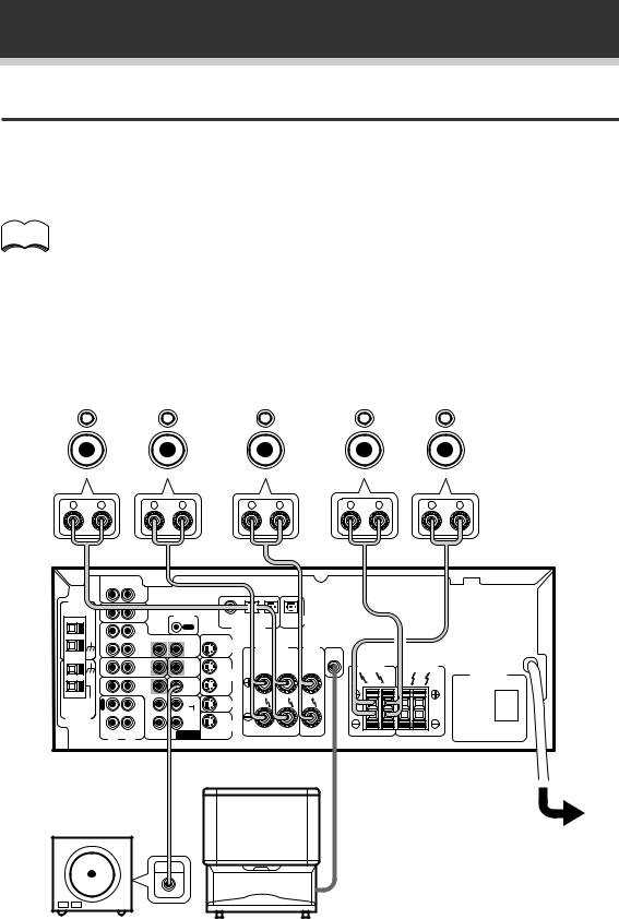
Connecting Speakers
A full complement of six speakers is shown here but, naturally, everyone’s home setup will vary. Simply connect the speakers you have in the manner described below. The receiver will work with just two stereo speakers (called “front” speakers in the diagram) but it is recommended to be used with at least three speakers.
Make sure you connect the speaker on the right to the right terminal and the speaker on the left to the left terminal. Also make sure the positive and negative (+/–) terminals on the receiver match those on the speakers.
The receiver has two speaker systems, A & B. A is the main system supporting the full complement of memo surround sound speakers. If you switch on both A & B speaker systems, only front speakers and the sub-woofer will be audible. No sound will come from the center or surround speakers but multi channel sources will be down-mixed to the active speakers so no sound will be lost. Similarly, if you choose just the B system you‘ll only hear the front speakers connected to the B system and multi channel sources
will be down-mixed to these two speakers.
• Use speakers with a nominal impedance of 8 Ω to 16 Ω.
|
Front Speakers (A) |
|
|
|
|
|
|
|
|
|
|
|
SURROUND |
|||||||||||||||||||||||||
|
Center Speaker |
|
|
|
|
Speakers |
||||||||||||||||||||||||||||||||
|
|
L |
|
|
|
R |
|
|
|
C |
|
|
SL |
|
|
|
|
|
|
SR |
||||||||||||||||||
|
|
|
|
|
|
|
|
|
|
|
|
|
|
|
|
|
|
|
|
|
|
|
|
|
|
|
|
|
|
|
|
|
|
|
|
|
|
|
|
|
|
|
|
|
|
|
|
|
|
|
|
|
|
|
|
|
|
|
|
|
|
|
|
|
|
|
|
|
|
|
|
|
|
|
|
|
|
VSX-D509S
AM LOOP |
IN |
|
|
|
|
|
|
|
|
|
|
|
|
|
|
|
AUX |
|
|
|
|
|
|
|
|
|
|
|
|
|
|
ANTENNA |
|
|
|
|
|
|
|
|
|
|
|
|
|
|
|
|
IN |
CD |
|
CONTROL |
|
|
|
|
|
|
|
|
|
|
|
|
|
|
|
COAX |
OPT1 |
OPT2 |
OPT |
DIGITAL |
|
|
|
|
|
||
|
|
|
|
|
|
|
|
|
|
||||||
|
|
|
|
|
|
PCM / 2/ DTS |
|
OUT |
|
|
|
|
|
||
|
O |
|
|
OUT |
|
|
|
|
|
|
|
|
|||
|
|
|
|
DIGITAL IN |
|
|
|
|
|
|
|
|
|||
|
U |
|
|
|
|
|
|
|
|
|
|
|
|
|
|
|
T |
VCR / |
|
|
|
|
|
|
|
|
|
|
|
|
|
|
|
DVR |
|
|
S |
TO |
|
|
A |
|
|
|
|
|
|
|
IN |
|
IN |
OUT |
TVMONTOR |
|
FRONT |
CENTER |
|
|
|
|
|
||
|
|
|
|
|
OUT |
|
SPEAKERS |
SPEAKERS |
CENTER |
|
|
|
|
||
|
|
|
|
|
|
|
|
|
|
|
PREOUT |
|
|
|
|
|
|
TV / |
|
TO |
S |
|
|
R |
L |
|
SURROUND |
|
FRONT |
B |
|
|
IN |
SAT |
IN |
MONTOR |
OUT |
|
|
|
SPEAKERS |
|
SPEAKERS |
||||
|
|
|
|
TV |
|
VCR / |
|
|
|
|
|
|
|
|
AC OUTLET |
|
|
|
|
|
S |
DVR |
|
|
|
|
R |
L |
R |
L |
|
|
IN |
DVD |
IN |
SUB |
|
|
|
|
|
|
|||||
|
/ LD |
WOOFER |
IN |
|
|
|
|
|
|
|
|
|
|
||
|
|
|
|
PREOUT |
|
|
|
|
|
|
|
|
|
|
|
FM |
R |
OUT R |
L |
S |
TV / |
|
|
|
|
|
|
|
|
|
|
UNBAL |
E |
IN |
SAT |
|
|
|
|
|
|
|
|
|
|||
75Ω |
C |
CD-R |
|
|
|
|
|
|
|
|
|
|
|
|
|
|
|
SURROUND |
|
|
|
|
|
|
|
|
|
|
|
||
FM |
L |
/TAPE |
|
S |
|
|
|
|
|
|
|
|
|
|
|
ANTENNA |
P |
/MD |
|
|
|
DVD |
|
|
|
|
|
|
|
|
|
|
A |
IN |
|
|
IN |
|
|
|
|
|
|
|
|
|
|
|
|
|
CENTER |
/ LD |
|
|
|
|
|
|
|
|
|
||
|
Y |
|
|
|
|
|
|
|
|
|
|
|
|
||
|
|
SUB |
DVD 5.1 CH |
R |
L |
WOOFER |
INPUT |
|
|||
|
|
Powered sub woofer
Be sure to complete all other connections before connecting
INPUT
this unit to the AC power source.
When using the speaker on your TV as the center speaker, connect the CENTER PREOUT jack on this unit to the audio input jack on your TV. In this case, the center speaker shown is unnecessary.
14
Connecting Your Equipment
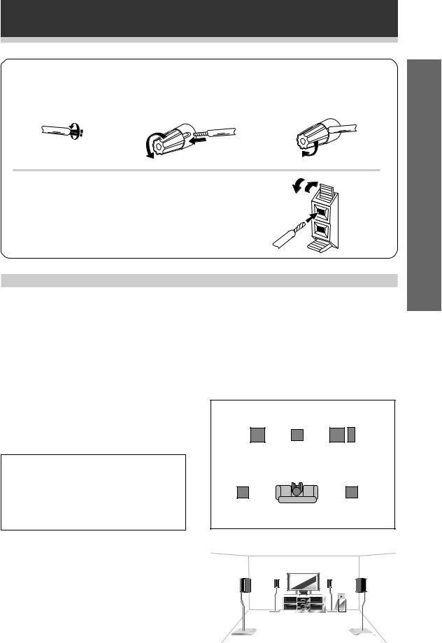
7 Speaker terminals
1 Twist exposed wire |
2 Loosen speaker |
3 Tighten terminal. |
strands together. |
terminal and insert |
|
|
exposed wire. |
|
1/2 inches
Use good quality speaker wire to connect the speakers to the |
|
|
receiver. |
|
|
1 Twist around 1/2 inch of bare wire strands together. |
ª |
|
2 Unclip the speaker terminal and insert the wire. |
||
3 Snap shut the speaker terminal to secure. |
||
|
||
|
· |
Hints on speaker placement
Speakers are usually designed with a particular placement in mind. Some are designed to be floorstanding, while others should be placed on stands to sound their best. Some should be placed near a wall; others should be placed away from walls. Follow the guidelines on placement that the speaker manufacturer provided with your particular speakers to get the most out of them.
•Place the front left and right speakers at equal distances from the TV.
•When placing speakers near the TV, we recommend using magnetically shielded speakers to prevent possible interference, such as discoloration of the picture when the TV is switched on. If you do not have magnetically shielded speakers and notice discoloration of the TV picture, move the speakers farther away from the TV.
•Install the center speaker above or below the TV so that the sound of the center channel is localized at the TV screen.
CAUTION!
If you choose to install the center speaker on top of the TV, be sure to secure it with putty, or by other suitable means, to reduce the risk of damage or injury resulting from the speaker falling from the TV in the event of external shocks such as earthquakes.
•If possible, install the surround speakers slightly above ear level.
•Try not to install the surround speakers farther away from the listening position than the front and center speakers. Doing so can weaken the surround sound effect.
To achieve the best possible surround sound, install your speakers as shown below. Be sure all speakers are installed securely to prevent accidents and improve sound quality.
Overhead view of speaker set up
Front |
|
Front |
Left |
Center |
Right |
Sub
Woofer
Surround |
Surround |
Left |
Right |
Listening
Position
3-D view of speaker set up
up Set
15
Preparations
Setting Up for Surround Sound
Be sure to switch the power of this unit on (The STANDBY indicator goes out).
To ensure the best possible surround sound, be sure to complete the following set up operations. This is particularly important when using the 2(Dolby) surround mode. You only need to make these settings once (unless you change the placement of your current speaker system or add new speakers, etc.). Refer to the following pages for detailed descriptions of the settings available for each mode.
VSX-D509S |
1 Press RECEIVER to turn the power on. |
|
The STANDBY indicator goes out. |
SOURCE RECEIVER 
 1
1
2 |
DVD |
TV |
VCR |
CD-R |
|
MULTI CONTROL |
|
||
|
RCV |
CD |
TUN |
TVC |
1 |
2 |
3 |
|
|
MIDNIGHT |
5.1CH |
ATT |
|
|
4 |
5 |
6 |
|
|
SIGNAL SELECT |
EFFECT |
|
||
7 |
8 |
9 |
|
|
+10 |
|
|
DISC |
|
|
0 |
ENTER |
|
|
TV CONTROL |
|
|
|
|
|
TV |
|
|
|
TV VOL |
TVFUNC MASTERVOLUME |
|
||
|
MENU |
|
|
|
|
CHANNEL |
|
|
|
|
|
FQ |
|
4 |
ST |
|
|
ST |
|
|
ENTER |
|
|
|
|
|
FQ |
|
3 |
8 |
|
|
|
|
D.ACCESS |
BAND |
CLASS |
||
3 |
1 |
¡ |
||
MPX |
DTV ON / OFF |
DTV MENU |
|
|
7 |
4 |
¢ |
|
|
2 |
DSP |
TEST TONE |
|
|
CH SELECT |
CH LEVEL |
FL DIMMER |
|
|
LOUDNESS FUNCTION |
MUTING |
SETUP |
|
|
Î
AV PRE-PROGRAMMED AND LEARNING
REMOTE CONTROL UNIT
VSX-D409 |
|
|
|
|
|
|
|
|
Î |
|
|
MULTI CONTROL |
|
|
|
DVD/LD TV/SAT VCR/DVR |
CD |
||
2 |
|
|
CD-R/ |
|
RECEIVER TUNER TAPE/MD TVCONT |
||||
2 DSPMODE MIDNIGHT 5.1CH |
||||
|
1 |
2 |
3 |
4 |
|
CHANNEL |
TEST |
ATT |
SIGNAL |
|
SELECT |
TONE |
SELECT |
|
5 |
6 |
7 |
8 |
|
|
CHANNEL |
EFFECT |
|
|
||
LEVEL |
|
|
|||
9 |
0 |
‡ |
ENTER |
|
|
|
|
10 |
DISC |
|
|
|
FUNC |
CH |
|
|
|
|
|
|
|
|
|
VOL |
TV CONTROL |
VOL |
|
|
|
|
|
|
|
||
|
FQ |
|
|
|
4 |
ST |
|
ST |
|
|
|
|
ENTER |
TOP |
|
||
|
|
|
|
||
MENU |
|
|
MENU |
||
|
FQ |
|
|
|
|
SOURCE CLASS |
MPX |
BAND |
|
3 |
|
|
7 |
8 |
3 |
||
D.ACCESS |
|
CHANNEL |
|
||
1 |
¡ 4 |
¢ |
|||
LOUDNESS FUNCTION |
MUTING |
|
|
|
|
1 |
FL |
REMOTE MASTER |
RECEIVER DIMMER |
SETUP VOLUME |
|
AUDIO/VIDEOPRE-PROGRAMMED |
||
REMOTECONTROLUNIT |
||
16
2 Press RCV.
This switches the remote to the surround setup mode. (On the VSXD409 the button is called RECEIVER.)
3 Press @ or #to select the mode you want to set.
For best results, start with “SPEAKERS setting mode” and make your initial adjustments in the order described below.
The current settings are displayed automatically.
SPEAKERS (Front, Center, Surround) setting mode (page 17)
Use to specify the type of speakers you have connected.
SUB WOOFER ON/PLUS/OFF setting mode (page 18)
Use to specify the sub woofer as on or off.
Crossover frequency setting mode (page 18)
Use to determine which frequencies will be sent to the sub woofer (or “Large” speakers if you don’t have a sub woofer).
LFE attenuator setting mode (page 18)
Use to specify the peak level for the LFE channel and the crossover network for rerouted bass frequencies.
Low cut filter ON/OFF setting mode (page 19)
Use to cut the distorted sound from the sub woofer.
FRONT speakers distance setting mode (page 19)
Use to specify the distance from your listening position to your front speaker.
CENTER speakers distance setting mode (page 19)
Use to specify the distance from your listening position to your center speaker.
SURROUND speakers distance setting mode (page 19)
Use to specify the distance from your listening position to your surround speakers.
Dynamic range control setting mode (page 20)
Use to compress the dynamic range of the sound track.
Dual mono setting mode (page 20)
Use with 2Digital software that has dual mono encoding if you want to isolate one channel or listen in this specialized mono mode.
Coaxial digital input setting (page 20)
Use to specify the input to be assigned to the coaxial digital input.
Optical digital input setting (page 21)
Use to specify the input to be assigned to the optical digital input.
4 Press % or fi to select the setting you want.
The setting is entered automatically.
5Repeat steps 3 and 4 to set other surround modes.
Press ENTER to exit the setting mode.
memo The setting mode is automatically exited if no operation is performed for 10 seconds.
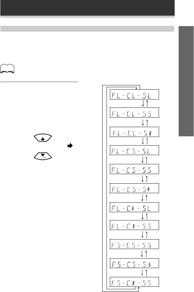
Preparations
SPEAKERS (Front, Center, Surround) setting mode
This setting establishes the size and configuration of the speaker system you have connected. So, for example, here you set whether you have connected surround speakers or not, and how big they are. Selecting “Large” or “Small” will determine how much bass is sent by the receiver to the speakers being set. This setup system has certain constraints. For example, all your speakers cannot be set to “Large,” you need to decide which speakers should receive the most bass and set them to “Large.”
In the display, “F”, “C”, and “S” refer to front, center, and surround speakers respectively. Speaker size is denoted as “L” for large speakers, “S” for small speakers, and “*” (asterisk) if no speaker is connected.
memo If the cone size (diameter) of the speaker is larger than 5 inches, please set to Large.
Switch the speaker setting mode according to the speakers you hooked up. Use the % or fi buttons.
The configurations shown on the right will appear in the display on the front of the receiver. One of them should match your speaker set up. Cycle through the different possibilities until you find the one that matches your set up.
FQ 
FQ
* Press # to advance to the next receiver setting, and press @to return to a previous receiver setting.
up Set
17
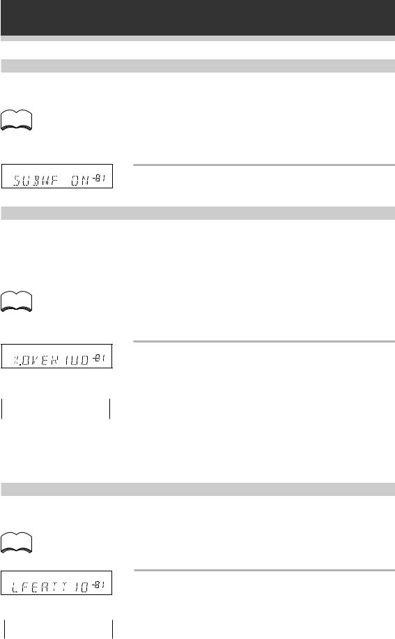
Preparations
SUB WOOFER ON/PLUS/OFF setting mode
Sets whether the SUB WOOFER is used or not. Also, when used you have the option to use the “PLUS” setting.
• Initial setting is “ON”.
memo • Setting the front speaker size to “Small” in the SPEAKERS setting mode automatically locks the sub woofer in the “ON” position.
•Use the PLUS for extra bass. When you use PLUS you will get the bass sounds from the sub woofer even if the front speakers are set to “Large”.
dB
Press % or fi to select sub woofer ON, PLUS or
OFF.
Crossover frequency setting mode
Crossover frequency is the point where the receiver divides the high and low sounds (the frequencies) between the speakers. Since most smaller speakers can’t handle deep bass tones, this setting allows you to send those sounds to the sub woofer (or speakers set to “Large” if you don’t have a sub woofer) instead of the speakers set to “Small” in your system. Choose the point at which you want the frequency routed to the sub woofer (or “Large” speakers).
We recommend setting this to 200 Hz if smaller bookshelf-type speakers are used for your “Small” speakers.
• Initial setting is “100 Hz”.
memo • If all speakers (front, center, and surround) are set to “Large” in SPEAKERS setting mode, crossover frequency cannot be set because there are no “Small” speakers (*** appears in the display).
dB
 100Hz
100Hz
 150Hz
150Hz
 200Hz
200Hz
Press % or fi to specify the crossover frequency for your small speakers (100 Hz, 150 Hz or 200 Hz).
100 Hz
Sends bass frequencies below 100 Hz to the sub woofer (or “Large” speakers).
150 Hz
Sends bass frequencies below 150 Hz to the sub woofer (or “Large” speakers).
200 Hz
Sends bass frequencies below 200 Hz to the sub woofer (or “Large” speakers).
LFE attenuator setting mode
Dolby Digital and DTS audio sources include ultra-low bass tones. Set the LFE attenuator as needed to prevent the ultra-low bass tones from distorting the sound from the speakers.
• Initial setting is “0 dB”.
memo • When ∞ is selected ( appears in the display), LFE is not available.
Press % or fi to set the attenuation level (0 dB,
dB |
10 dB or dB(∞)). |
|
 0 dB
0 dB 
 10 dB
10 dB
 ∞ (display "**")
18
 Loading...