


VSX-21TXH
Table of contents
 Loading...
Operating Instructions
– Advanced MCACC PC Display Application Software –
audio/video multi-channel receiver

About this manual
Continue
These are the Operating Instructions for an application which displays on your computer screen the
listening room reverberation frequency characteristics and the MCACC parameters measured by the
Advanced MCACC function of your VSX-23TXH, VSX-21TXH, VSX-9140TXH or VSX-9040TXH.
It explains everything you need to know to use the application, from installation to troubleshooting. You will
need to operate the receiver to use this application, so please refer also to the Operating Instructions
supplied with the receiver.
About the Advanced MCACC Application
The functions of the Advanced MCACC application are used with the same purpose as the “Reverb View”
functions of the receiver itself (see page 84 of the receiver’s Operating Instructions), namely to display the
reverberation characteristics of the listening environment. Using a computer provides cleaner, more easily
readable graphs. The application can also be used to display the measurement values stored in the
receiver’s MCACC memory.
Requirements for using the application on your PC
• The computer must be a PC functioning with one of the following operating systems: Microsoft®
Windows® Vista Home Basic/Home Premium/Ultimate SP1, Windows® XP Professional/Home Edition
SP3 or Windows
• The monitor must have a display resolution of 800 x 600 dots (SVGA) or greater.
• An RS-232C port connector is necessary for graphical output. Refer to the PC’s operating instructions
and/or the PC manufacturer for more information on making the proper port settings.
Microsoft®, Windows®Vista, Windows®XP and Windows®2000 are either registered trademarks or trademarks of
Microsoft Corporation in the United States and/or other countries.
®
2000 Professional SP4.
Main features of the application
1. Displays 3D graphs of the reverberation frequency characteristics of your room. You can choose to
see these measurements both with and without the equalization performed by this receiver (before
and after calibration).
2. Allows you to display a list of the Advanced MCACC parameters (the results of measurements).
3. Allows you to view graphs in a number of different formats.
4. Allows you to save the various measured data on the computer.
5. Allows you to make memos about the conditions in your room when you made the measurements,
etc.
6. Allows you to print the various graphs and the MCACC measurement values.
2

About the Advanced MCACC Application (Continued)
Things you can accomplish with this application
1. Advanced EQ Setup, which you can do with the receiver (see page 84 of the receiver’s Operating
Instructions), allows you to choose the optimum time period for auto EQ setup. You can use this
application’s reverberation characteristics (Reverb) as a guide in choosing the best time period for
your room.
For details, see Deciding the time period for Advanced EQ Setup calibration
2. Skewed reverb frequency characteristics in your listening room can prevent you from enjoying an
accurate sound field. The graphs displayed by this application are a powerful tool because they
allow you to check these reverb frequency characteristics at a glance. You can also check the
effectiveness of steps that you take to improve the acoustics of your listening room, for example,
installing sound absorbent material.
For details, see Checking steps to improve your room’s reverb characteristics
3. The reverb characteristics after calibration can be displayed. This lets you to check the EQ effects of
the Advanced MCACC measurements you have made.
For details, see About the display of the reverb characteristics graphs before and after calibration
(page 23).
4. The MCACC parameter display (Parameters) allows you to display on the computer all the
parameters (measurement values) stored in the receiver’s MCACC memories.
For details, see Display of the MCACC parameters (page 25).
(page 19).
(page 21).
3
Installing the Application
Continue
Install this application on your PC by using the downloaded installer.
You will find the installer in the folder that you specified when you downloaded the application.
If a previous version of the Advanced MCACC application (“Ver. 1.1”, “Ver. 1.4”, “Ver. 2.0” or “Ver. 2.1”) is
installed on your computer, please update the application. For details, see Updating the application
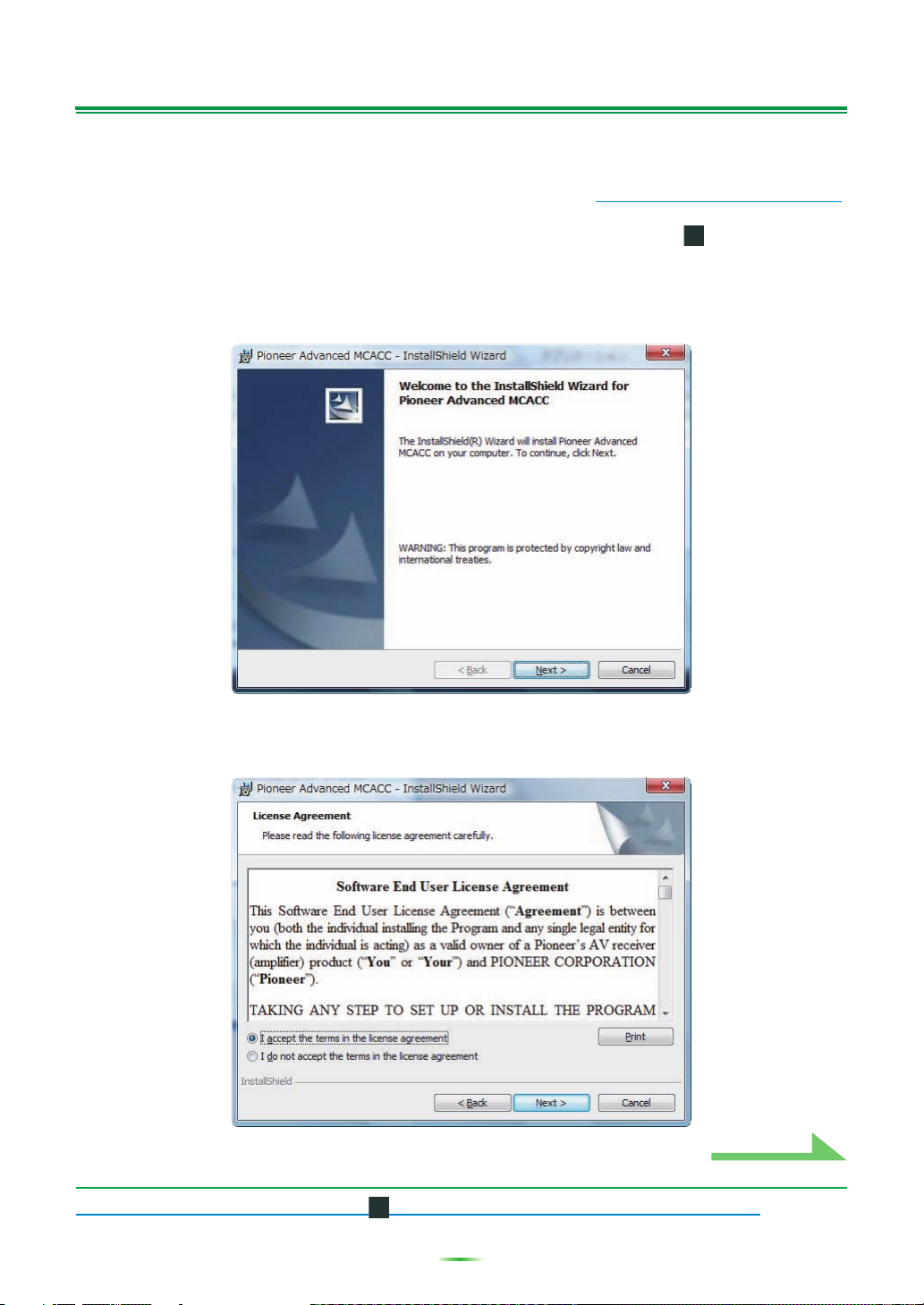
1 Double click the “PioneerAdvancedMCACC_e_ver_*_*.exe” file .
The number after “ver” in the filename is the version number of the installer.
Depending on the current configuration of your PC, the InstallShield Wizard can take some time to appear.
2 Click “Next”.
(page 26).
3 (If you agree to the contents of the License Agreement), select “I accept the
terms in the license agreement”, then select “Next”.
The destination selection screen of the installer appears.
Troubleshooting
If an error occurs when you double click and you are unable to proceed with the installation.
4
Installing the Application (Continued)
Continue
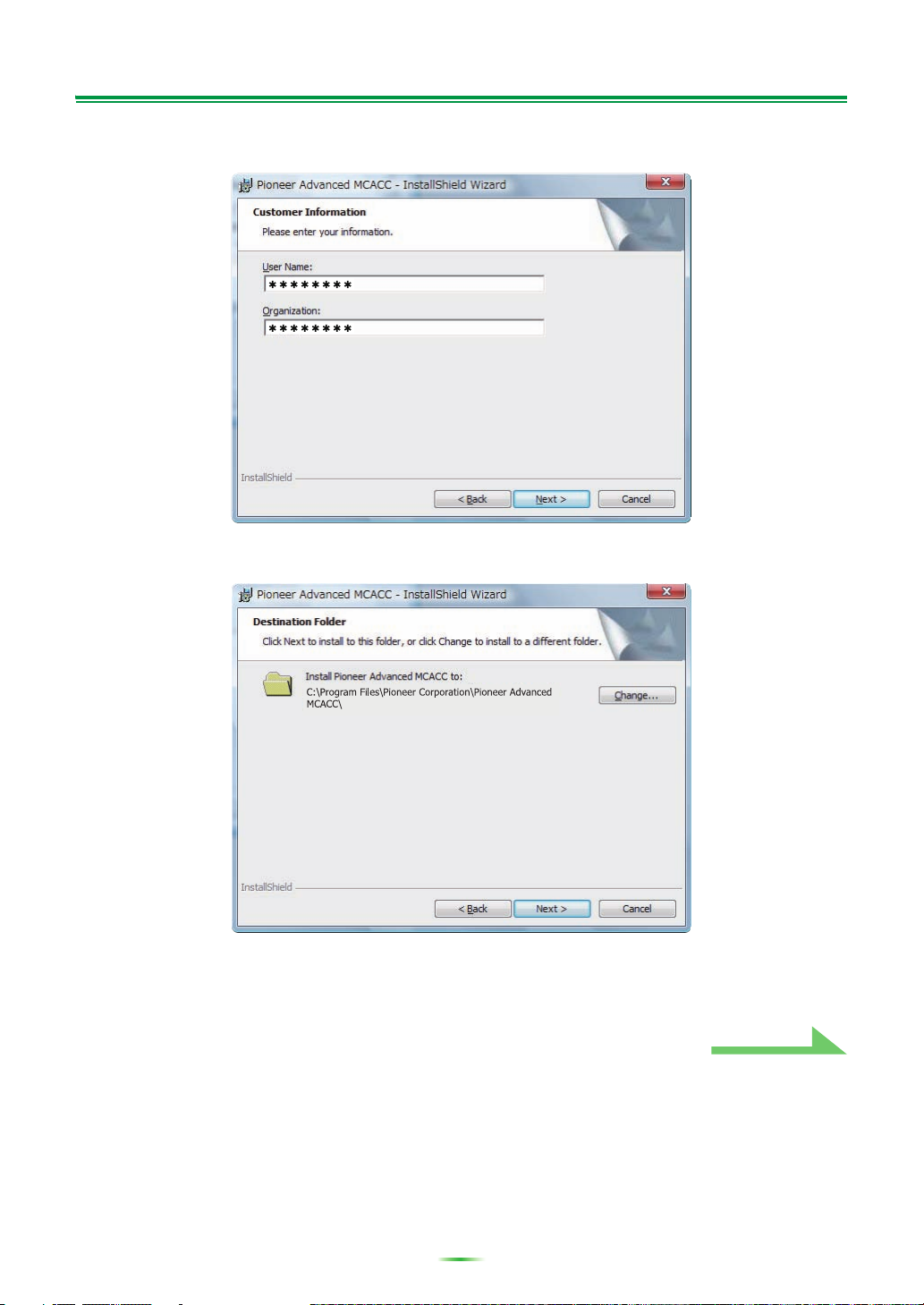
4 Input the Customer Information, then select “Next”.
5 Click “Next”.
The application is installed in the folder indicated at “Destination Folder”. The destination folder can be
changed by clicking “Change...”.
5
Installing the Application (Continued)
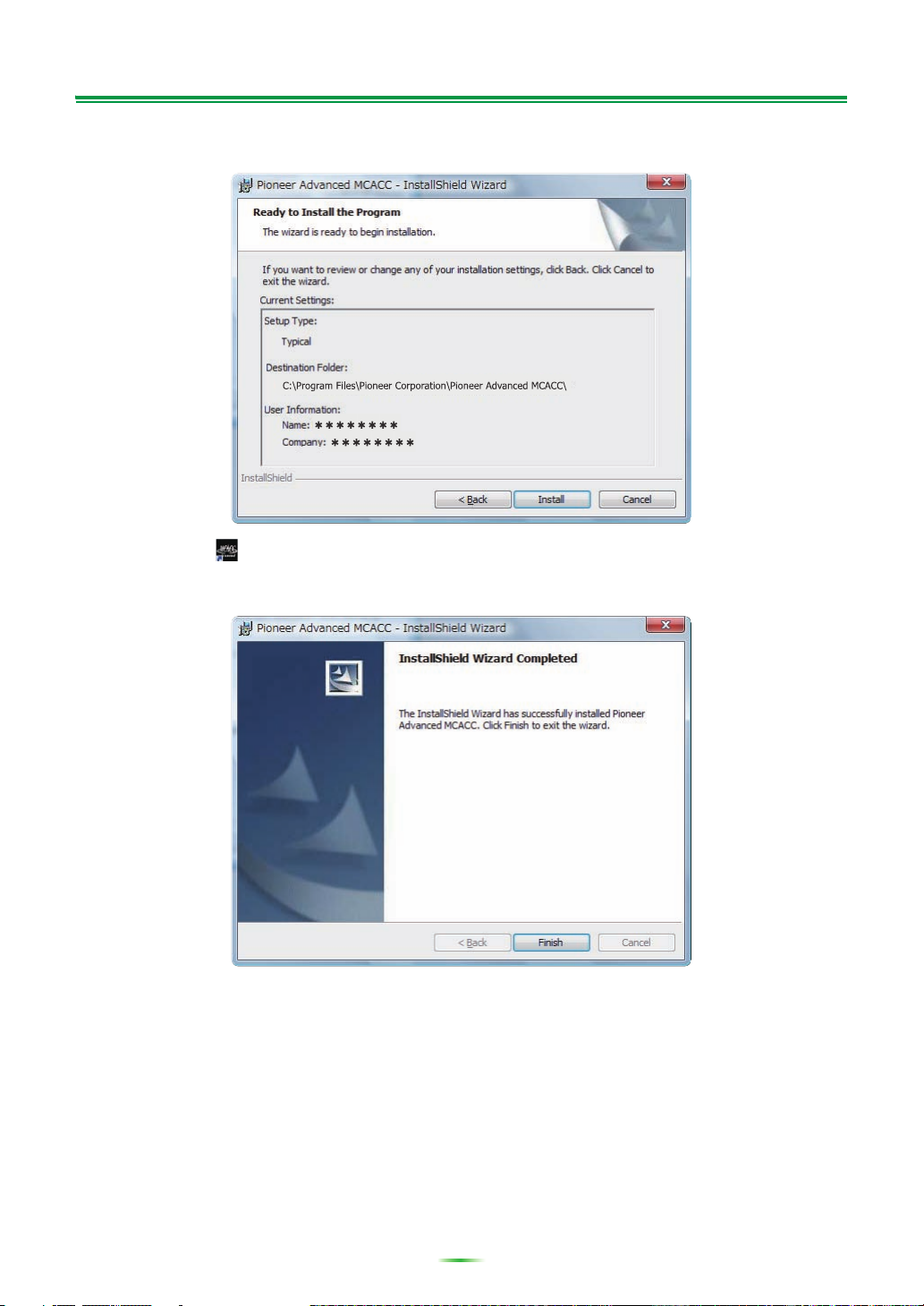
6 Choose “Install”.
A shortcut icon is created on the desktop.
7 Click “Finish”.
The installation is complete.
6
Operations on the Receiver and Cable Connections
RS-232C
RS-232C
PC
VSX-23TXH/VSX-21TXH/
VSX-9140TXH/VSX-9040TXH
Female-female
cross cable
Dsub 9-pin female
Dsub 9-pin female
Dsub 9-pin female
Dsub 9-pin female
Continue
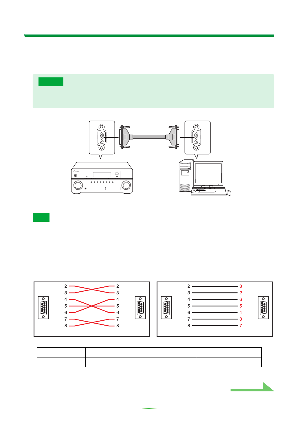
Connect the receiver and the computer in order to display on the computer the various data measured on
the receiver itself.
1 Connect the receiver to your PC with an RS-232C cable.
Caution
Before making or changing connections, switch off the power and disconnect the power cord from
the power outlet. Plugging in components should be the last connection you make with your
system.
Note
• When using a notebook computer or other computer without an RS-232C terminal, this application can
be used by connecting the receiver via USB using a commercially available USB-RS-232C conversion
cable (USB-Serial cable). When using USB connections, be sure to select the proper COM port
number for data transmission (see page 9
• The type of cable to use is a female-female cross cable. Different manufacturers use different names to
refer to this type of cable. Sometimes it is called an “interlink” cable, and sometimes it is called a
“reverse” cable.
).
Pin-out diagram of RS-232C cable to connect receiver and PC
• The following cable has been proved to ensure system operation.
Brand Cable Part NO.
Belkin Pro Series Serial Direct Cable-10 feet F3B207-10
7
Operations on the Receiver and Cable Connections (Continued)
a. Speaker Setting
b. Channel Level
c. Speaker Distance
2.MCACC Data Check
d. Standing Wave
e. Acoustic Cal EQ
f. Output PC
A/V RECEIVER
Exit Return
Start the MCACC application on your PC.
2f.Output PC
Exit Cancel
2 Perform the “Full Auto MCACC” operation on the receiver. (See page 41 of the
receiver’s Operating Instructions.)
The measurements here are not required if the “Full Auto MCACC” operation has already been
performed before connecting the RS-232C cable. Proceed to step 3.
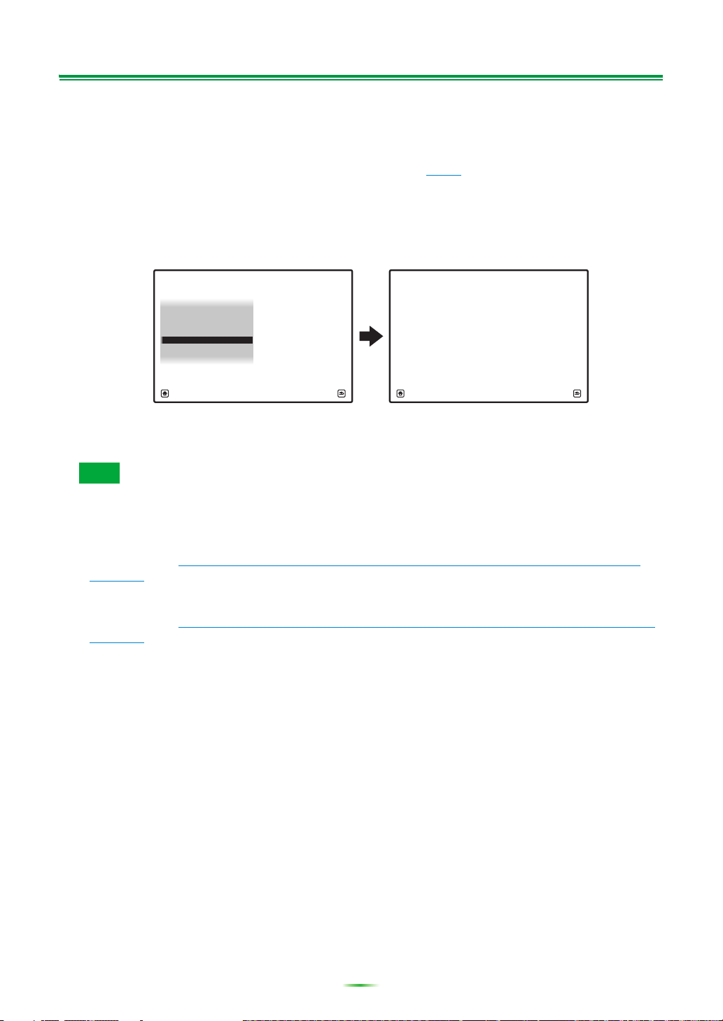
3 Select “Output PC” from “MCACC Data Check”. (See page 88 of the receiver’s
Operating Instructions.)
The message “Start the MCACC application on your PC” appears on the monitor screen and the receiver
enters the transmission standby mode. It is ready to send data to your PC.
This completes the preparations for sending the measurement data to your PC.
(To send the data, proceed to the next section Application Operations.)
Note
• The graphs for both before calibration (“Before”) and after calibration (“After”) can be displayed on the
screen displaying the reverberation characteristics graphs after Full Auto MCACC measurements
(“Reverb”), but note that the graph displayed for the characteristics after calibration is a prediction of
the reverberation characteristics after Full Auto MCACC with the EQ Type : SYMMETRY.
For details, see About the display of the reverb characteristics graphs before and after calibration
(page 23).
If you want to check the graph of the actually measured reverberation characteristics after MCACC
calibration (not the prediction), measure the reverb characteristics again after calibration.
For details, see Displaying the reverb characteristics after EQ calibration (actually measured values)
(page 24).
8
Applications Operations
COM port selection box
Continue
This section explains operations that you do in the application, from receiving measurement data to
displaying graphs and saving the data.
Receiving measurement data
1 Double click the application shortcut icon on the PC desktop.
You can also start the application by selecting “Program” “Pioneer Corporation” “Advanced
MCACC” from the “Start” menu.
The application starts.
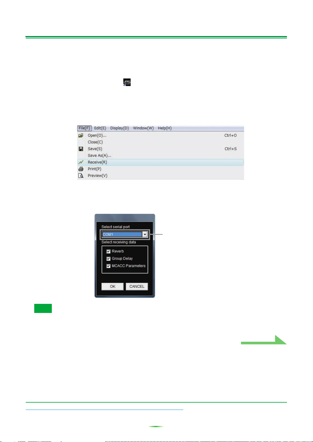
2 Select “Receive” under “File” on the menu bar.
3 Select the number of the COM port to which the RS-232C cable is connected.
A COM port between “COM1” and “COM8” can be selected. If you do not know which COM port
number to select, try selecting each port in turn, beginning with “COM1”.
Note
For more information about COM port settings, either refer to the operating instructions of your PC or
contact your PC’s manufacturer.
Troubleshooting
If an error occurs when you select “Receive” and no data is sent.
9
Application Operations (Continued)
Type of data
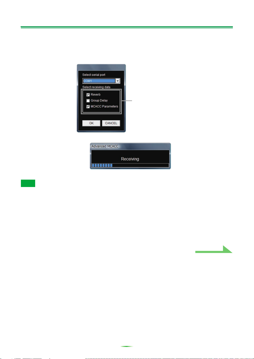
4 Select the type of data to be received, then select “OK”.
Select “Reverb” to receive the data for the room’s reverb characteristics, and “MCACC Parameters” to
receive the data for the various MCACC parameters (measurements results). The “Group Delay” function
is not used on this receiver. Nothing is displayed if “Group Delay” is selected.
Data transmission starts.
When reception finishes the received data appear.
Note
• The data used to display the reverberation characteristics graph (Reverb) and the MCACC parameters
are not deleted even when the receiver’s power is turned off. However, for the data used to display the
reverberation characteristics graph (Reverb), the data stored in the receiver is overwritten when the
reverberations are measured again. If you wish to display graphs of multiple sets of data, use the data
transfer function to store the data on a computer each time you measure the reverberations.
• In order to avoid malfunction, after the completion of the data transmission, unplug the RS-232C cable
connecting your PC and the receiver.
Continue
10
Application Operations (Continued)
1
2
3
4
5
6
7
8
9
10
11
12
13
14
15
Continue
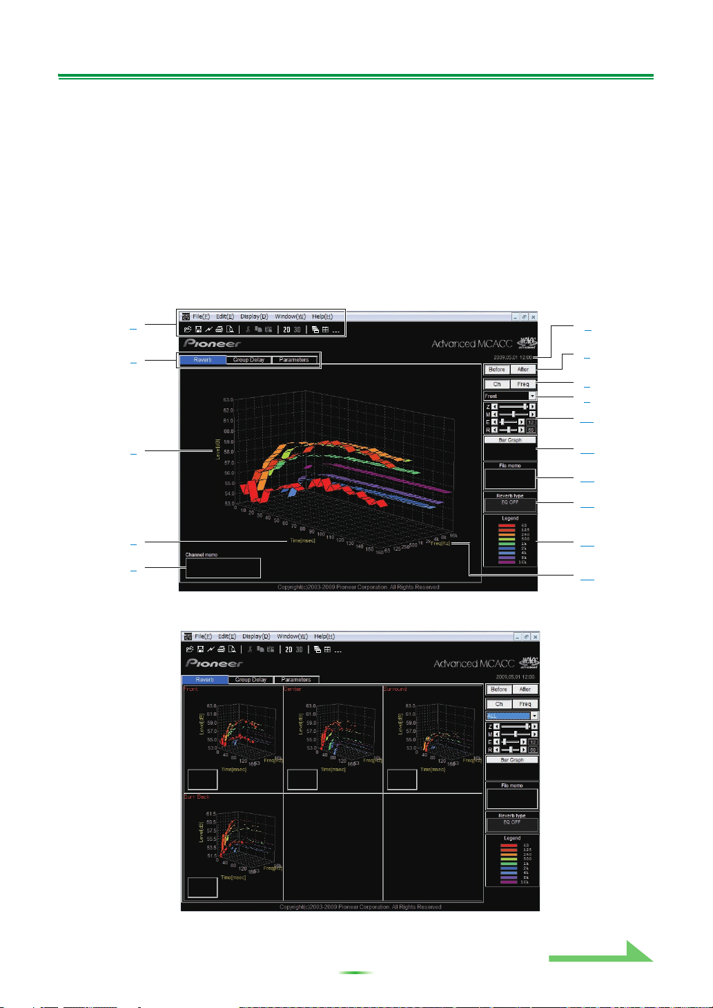
Graph and parameter displays (names and functions of parts)
When measurement data is received, the graphs and parameters display window appears. The display
window is divided into two items, “Reverb” and “Parameters”. Select the desired tab to switch to that
window and display the respective details. The “Group Delay” function is not used on this receiver. Nothing
is displayed if “Group Delay” tab is selected.
Reverb (graph of the room’s reverberation frequency characteristics)
The display can be switched between the reverb characteristics graphs before and after calibration. You
can switch the display between individual displays for the different channels/frequencies or a list display of
all the channels/frequencies (ALL). Below we explain the different parts of the individual displays and the
ALL display, using the channel display as an example.
Individual display (Example: Front channel)
ALL display
11
Loading...