


PIONEER NEW MEDIA TECHNOLOGIES, INC.
CLD-V2600
& CLD-V2400
See inside this Reference Guide for:
Level I — Manual Control of the CLD-V2600 & CLD-V2400
Level III — Computer Control of the CLD-V2600 & CLD-V2400
And CLD-V2400
LASERDISC/COMPACT DISC PLAYERS
LEVEL I & III
U S E R ’ S M A N U A L
PROGRAMMER’S REFERENCE GUIDE
Pioneer Technical Publication TP 117 V. 2.0 12/93

PIONEER NEW MEDIA TECHNOLOGIES, INC.
A
LASERDISC/COMPACT DISC PLAYERS
LEVEL I & III
U S E R ’ S M A N U A L
PROGRAMMER’S REFERENCE GUIDE
Pioneer Technical Publication TP 117 V. 2.0 12/93

CLD-V2600 / 2400 Level I & III • NOTE TO USERS
CLD-V2600/2400 Level I & III Documentation
For Manual and Computer Control
Note to Users
This manual is based on the most up-to-date information for Level I and Level III program development and delivery on the CLD-V2600 & CLD-V2400 available at the time of publication. It is subject to change without notice. Although every reasonable effort has been made to include accurate information, the statements in this document are not warranties.
Pioneer New Media Technologies, Inc., makes no warranty or claims as to the accuracy, completeness or fitness for any particular purpose of the technical information provided herein. Throughout this manual NOTES appear reflecting details of the particular player functions which may be different on future players. The NOTES are included to aid understanding, but should not be depended upon in designing applications.
Please fill out the Registration Form on the next page and return it to the Pioneer address below to insure that you receive updated versions of the Level I & III Manual for the CLD-V2600/2400, and related support materials as they become available. Also, comments, observations, and/or corrections regarding this document would be appreciated.
Return Registration Form to and for more information contact:
Pioneer New Media Technologies, Inc. Engineering and Product Development Engineering Support
600 East Crescent Ave. Upper Saddle River, NJ 07458 201/327-6400
FAX: 201/327-9379
East Coast Engineering Support:
201/327-6400
West Coast Engineering Support:
310/952-2111
CLD-V2600 / 2400 Level I & III User’s Manual TP 117 v. 2.0 • 12/93

|
|
|
|
|
|
|
|
|
|
|
|
|
|
|
Addition — CLD-V2600 User’s Manual |
#1 — 11/94 |
|||
|
|
|
|
|
Additional Error Messages
The RS-232 Error Messages described on page 4-3 of the CLD-V2600 User’s Manual, also appear on the front panel illuminated display of CLD-V2600 players. There are two additional Error Messages that you may also see on the display. These two additional Error Messages are not returned in response to any RS-232 commands, but only appear on the front panel display. Here is a brief description of each:
1)E07 — Unrecoverable error
The player may read a portion of the disc, then spin it down. If the E07 error occurs when the player is reading material at the outside of the disc, check to make sure that the disc is not warped.
Lay the disc on a flat surface. If you can slide a dime under the center hole of the disc, it is warped. Check both sides. If the disc is warped, leave it on the flat surface, place several heavy books on it and leave it overnight. This will flatten out the disc, then you can try to play it again. Also, make sure the disc is free of scratches or greasy finger prints.
If the player still spins down the disc when searching or playing to the higher numbers of the disc, and you see the E07 error on the illuminated front panel, the player may need service. Call 1-800-872-4159 for your nearest Authorized Service Center.
2)E03 — Mis-clamp condition on spin-up
The player begins to spin up the disc, then immediately spins it down and you see the E03 error on the illuminated front panel of the player. This error can be caused by a disc that is out of specification. Try playing several different discs.
If the problem persists, and you see the E03 error on the front panel after trying to play several different discs, the player may need service. Call 1-800-872-4159 for your nearest Authorized Service Center.
Multimedia Systems Division, Engineering/Technical Support |
201/327-6400 |

CLD-V2600 / 2400 Level I & III • REGISTRATION
CLD-V2600/2400
Level I & III Documentation
For Manual and Computer Control
Registration Form
Name: |
|
Title: |
|
|
|
|||||
|
|
|
|
|
|
|
|
|
|
|
Company: |
|
|
|
|
|
|
||||
Address: |
|
|
|
|
|
|
||||
City: |
|
State: |
|
Zip: |
|
|||||
Phone: |
|
Date: |
|
|
|
|||||
Comments: |
|
|
|
|
|
|||||
Please return this Registration Form and any comments you might have about this manual to:
Pioneer New Media Technologies, Inc. Engineering and Product Development Engineering Support
600 East Crescent Avenue
Upper Saddle River, NJ 07458-1827 201/327-6400
FAX: 201/327-9379
CLD-V2600 / 2400 Level I & III User’s Manual TP 117 v. 2.0 • 12/93

CLD-V2600 / 2400 Level I & III • Table Of Contents
CLD-V2600/2400 LEVEL I & III DOCUMENTATION
For Manual and Computer Control
Note to Users
User Registration Form
CONTENTS
1. Introduction........................................................................... |
1 - |
1 |
|||
1.1 |
Scope of Level I & III Manual ................................. |
1 |
- |
1 |
|
1.2 |
Features of the CLD-V2600 & CLD-V2400 ......... |
1 |
- |
1 |
|
1.3 |
Special Features of the CLD-V2600 ..................... |
1 |
- |
2 |
|
1.4 |
Overview of Player Control Methods.................... |
1 |
- |
2 |
|
1.5 |
Chapter Highlights..................................................... |
1 |
- |
7 |
|
2. Operational Basics............................................................ |
2 |
- |
1 |
||
2.1 |
Internal Operations ................................................... |
2 |
- |
1 |
|
|
2.1.1 |
Operating Modes .............................................. |
2 |
- |
1 |
|
2.1.2 |
Active States...................................................... |
2 |
- |
1 |
2.2 |
Player Indicators - CLD-V2600 & CLD-2400...... |
2 |
- |
3 |
|
2.3 |
Interfaces ...................................................................... |
2 |
- |
8 |
|
|
2.3.1 |
Remote Sensor & The Barcode Terminal ..... |
2 |
- |
8 |
|
2.3.2 |
RS-232C Interface Connector ......................... |
2 |
- 10 |
|
2.4 |
Function Switches ..................................................... |
2 |
- 13 |
||
2.5 |
On-Screen Displays in Manual Mode ................ |
2 |
- 14 |
||
|
2.5.1 |
Area 1: Chapt./Frame /Track /Time Displ. |
2 |
- 14 |
|
|
2.5.2 Area 2: Audio, Speed, Repeat, CLV Display .... |
2 |
- 16 |
||
|
2.5.3 |
Area 3: Argument Display .............................. |
2 |
- 19 |
|
|
2.5.4 |
Area 3: Address Flag Display ........................ |
2 |
- 19 |
|
CLD-V2600 / 2400 Level I & III User’s Manual TP 117 v. 2.0 • 12/93 |
I |

Table of Contents • CLD-V2600 / 2400 Level I & III
3. Manual Control — Level I............................................. |
3 |
- |
1 |
|||
3.1 |
Front Panel Control ................................................... |
3 |
- |
1 |
||
|
3.1.1 |
Stop-Open/Close (CLD-V2600 & CLD-V2400) .... |
3 |
- |
1 |
|
|
3.1.2 |
Play (CLD-V2600 & CLD-V2400) ........................... |
3 |
- |
2 |
|
|
3.1.3 |
Pause (CLD-V2600) .............................................. |
3 |
- |
2 |
|
|
3.1.4 Skip Fwd/Rev (CLD-V2600 & CLD-V2400) ......... |
3 |
- |
2 |
||
|
3.1.5 Scan Fwd/Rev |
|
|
|
||
|
|
(CLD-V2400 Button; CLD-V2600 Dial) ............... |
3 |
- |
3 |
|
|
3.1.6 |
Still |
Step Fwd/Rev (CLD-V2600) .................... |
3 |
- |
3 |
|
3.1.7 |
Display ON/OFF (CLD-V2600) .......................... |
3 |
- |
3 |
|
3.2 Remote Control ......................................................... |
3 |
- |
4 |
|||
|
3.2.1 Remote Control /CU-V113 & RU-V103......... |
3 |
- |
4 |
||
|
3.2.2 Description of Remote Control Functions .... |
3 |
- |
4 |
||
|
|
1) |
Reject ....................................................... |
3 |
- |
6 |
|
|
2) |
Pause ....................................................... |
3 |
- |
6 |
|
|
3) |
Play........................................................... |
3 |
- |
6 |
|
|
4) |
Repeat Mode........................................... |
3 |
- |
7 |
|
|
5) |
Still/Step Forward/Reverse.............. |
3 |
- |
9 |
|
|
6) |
Display..................................................... |
3 |
- |
9 |
|
|
7) |
Scan Forward/Reverse ...................... |
3 |
- |
9 |
|
|
8) |
Audio........................................................ |
3 |
- 10 |
|
|
|
9) |
Speed Set Down/Up........................... |
3 |
- 11 |
|
|
|
10) |
Clear......................................................... |
3 |
- 12 |
|
|
|
11) |
Multi-Speed Forward/Reverse........... |
3 |
- 12 |
|
|
|
12) |
Search...................................................... |
3 |
- 12 |
|
|
|
13) |
Chapter / Frame Track / Time ....... |
3 |
- 13 |
|
3.3 |
Barcode Control .......................................................... |
3 |
- 15 |
|||
|
3.3.1 LB Original Commands and LB2.................. |
3 |
- 15 |
|||
|
3.3.2 |
Barcode-CD™ Commands ............................. |
3 |
- 15 |
||
|
3.3.3 |
Creating Barcodes........................................... |
3 |
- 15 |
||
|
3.3.4 LaserBarcode, LB2 and BC-CD Logos......... |
3 |
- 16 |
|||
|
3.3.5 |
Pioneer Barcoce Readers ............................... |
3 |
- 17 |
||
|
3.3.6 Barcode Formats & Player Compatibility ... |
3 |
- 17 |
|||
|
3.3.7 |
Notes.................................................................. |
3 |
- 17 |
||
II |
TP 117 v. 2.0 • 12/93 CLD-V2600 / 2400 Level I & III User’s Manual |

CLD-V2600 / 2400 Level I & III • Table of Contents
4. External Computer Control — Level III ............... |
4 |
- |
1 |
||||
4.1 |
Command and Status |
................................................ |
4 |
- |
1 |
||
|
4.1.1 Request Status................................................ |
|
4 |
- |
2 |
||
4.2 |
Error Messages ............................................................ |
|
|
4 |
- |
3 |
|
4.3 |
Initial Settings ............................................................ |
|
|
4 |
- |
4 |
|
4.4 |
Level III Commands for .........LD & CD Control |
4 |
- |
5 |
|||
4.5 |
Command Formats .................................................... |
|
4 |
- |
7 |
||
4.6 |
Status Returns ............................................................ |
|
|
4 |
- |
9 |
|
4.7 |
Level III Command Descriptions........................... |
4 |
- 11 |
||||
|
4.7.1 Player Control Commands .............................. |
4 |
- 11 |
||||
|
1) |
Door Open ..................................OP |
4 |
-11 |
|||
|
2) |
Door Close ..................................CO |
4 |
-11 |
|||
|
3) |
Reject RJ.......................................... |
|
4 |
-12 |
||
|
4) |
Start |
SA ........................................... |
|
4 |
-12 |
|
|
5) |
Play |
PL............................................. |
|
4 |
-13 |
|
|
6) |
Pause PA.......................................... |
|
4 |
-14 |
||
|
7) |
Still |
ST ............................................. |
|
4 |
-14 |
|
|
8) |
Step Forward ..............................SF |
4 |
-15 |
|||
|
9) |
Step Reverse ...............................SR |
4 |
-15 |
|||
|
10) |
Scan Forward ..............................NF |
4 |
-15 |
|||
|
11) |
Scan Reverse ..............................NR |
4 |
-15 |
|||
|
12) |
Multi-Speed ..................Forward MF |
4 |
-16 |
|||
|
13) |
Multi-Speed ...................Reverse MR |
4 |
-16 |
|||
|
14) |
Speed Set .................................... |
SP |
4 |
-17 |
||
|
15) |
Search SE ........................................ |
4 |
-18 |
|||
|
16) |
Stop Marker ...............................SM |
4 |
-20 |
|||
|
17) |
Frame Set ...................................FR |
4 |
-21 |
|||
|
18) |
Chapter Set ................................CH |
4 |
-21 |
|||
|
19) |
Time Set TM..................................... |
4 |
-22 |
|||
|
20) |
Track Set .................................... |
TR |
4 |
-22 |
||
|
21) |
Index Set ..................................... |
IX |
4 |
-23 |
||
|
22) |
Block Set .................................... |
BK |
4 |
-23 |
||
|
23) |
Clear CL........................................... |
|
4 |
-24 |
||
|
24) |
Lead-Out Symbol ........................LO |
4 |
-24 |
|||
CLD-V2600 / 2400 Level I & III User’s Manual TP 117 v. 2.0 • 12/93 |
III |

CLD-V2600 / 2400 Level I & III • Table of Contents
4.7 Level III Command Descriptions (cont.) |
|
|
||
4.7.2 Player Control Switch Commands ................. |
|
4 - 25 |
||
25) |
Audio Control |
AD ...................................... |
|
4 -25 |
26) |
Video Control |
VD....................................... |
|
4 -25 |
27) |
Key Lock KL............................................... |
|
|
4 -27 |
4.7.3 Display Control Commands ............................ |
|
4 - 28 |
||
28) |
Display Control DS ................................... |
|
4 - 28 |
|
29) |
Clear Screen |
CS ........................................ |
|
4 - 29 |
30) |
Print Character PR.................................... |
|
4 - 30 |
|
4.7.4 Request Commands ......................................... |
|
4 - 31 |
||
31) |
Frame Number Request ?F ..................... |
|
4 - 31 |
|
32) |
Chapter Number Request ?C ................... |
|
4 - 31 |
|
33) |
Time Number Request ?T......................... |
|
4 - 32 |
|
34) |
Track Number Request ?R ....................... |
|
4 - 32 |
|
35) |
Index Number Request ?I......................... |
|
4 - 33 |
|
36) |
Block Number Request ?B ....................... |
|
4 - 33 |
|
37) |
P-Block Number Request ?A .................... |
|
4 - 33 |
|
38) |
TOC Information Request ?Q................... |
|
4 - 34 |
|
39) |
Player Active Mode Request ?P............... |
|
4 - 35 |
|
40) |
LD Disc Status Request ?D...................... |
|
4 - 36 |
|
41) |
CD Disc Status Request ?K...................... |
|
4 - 36 |
|
42) |
LVP Model Name Request ?X ................... |
|
4 - 37 |
|
4.7.5 Communication Control Commands.............. |
|
4 - 38 |
||
43) |
Communication Control CM .................... |
|
4 - 38 |
|
44) |
CCR Mode Request ?M ............................. |
|
4 - 38 |
|
4.7.6 Register Control Commands........................... |
|
4 - 39 |
||
45) |
Register A Set (Display) RA ...................... |
|
4 - 39 |
|
46) |
Register B Set (Squelch Control) RB........ |
4 - 42 |
||
47) |
Register C Set (Miscellaneous) RC........... |
|
4 - 43 |
|
48) |
Register A Request (Display) $A............... |
|
4 - 44 |
|
49) |
Register B Request (Squelch Control) |
$B .. |
4 - 44 |
|
50) |
Register C Request (Miscellaneous) |
$C ... |
4 - 45 |
|
4.7.7 Input Device Control Commands ................... |
|
4 - 46 |
||
51) |
Input Unit Request #I............................... |
|
4 - 46 |
|
52) |
Input Number Wait ?N.............................. |
|
4 - 46 |
|
IV |
TP 117 v. 2.0 • 12/93 CLD-V2600 / 2400 Level I & III User’s Manual |

CLD-V2600 / 2400 Level I & III • Table of Contents
Appendices:
Appendix |
A: |
Level III Commands .......................................... |
A - |
1 |
Appendix |
B: |
Remote Control Units |
|
|
|
|
• CU-V113 and RU-V103............................. |
B - |
1 |
Appendix |
C: |
Interface Cable Specifications......................... |
C - |
1 |
Appendix |
D: |
LaserBarcode™ & LB2™ Commands, Logo ... |
D - |
1 |
Appendix |
E: |
Barcode CD™ Commands & Logo.................. |
E - |
1 |
Appendix |
F: |
Barcode Formats and Player Compatibility.. |
F - |
1 |
Appendix |
G: Pioneer Barcode Readers |
|
|
|
|
|
• UC-V109BC & UC-V108BC................................... |
G - |
1 |
Appendix |
H: Internal Player Controls ................................... |
H - |
1 |
|
Appendix |
I: |
Internal Player Registers ................................... |
I - |
1 |
Appendix |
J: |
Additional Notes ................................................. |
J - |
1 |
Accompanying Figures, by Chapter
Figure No. |
Title |
|
Page No. |
||||
Chapter One |
|
|
|
|
|
||
Figure |
1 |
- A |
Controlling CLD-V2600/2400 LD/CD Players |
..... 1 |
- |
4 |
|
Figure |
1 |
- B |
Level I — Manual Control .................................... |
|
1 |
- |
5 |
Figure |
1 |
- C |
Level III — External Computer Control ................ |
|
1 |
- |
6 |
Chapter Two |
|
|
|
|
|
||
Figure |
2 |
- A |
Operating Modes ................................................ |
|
2 |
- |
2 |
Figure |
2 |
- B |
Transitions Between Active States ...................... |
|
2 |
- |
3 |
Figure |
2 |
- C |
CLD-V2600 Front Illuminated DISPLAY WINDOW . 2 |
- |
4 |
||
Figure |
2 |
- D |
CLD-V2600 FrontPanel View............................... |
|
2 |
- |
5 |
Figure |
2 |
- E |
CLD-V2600 Rear Panel View ............................... |
|
2 |
- |
6 |
Figure |
2 |
- F |
CLD-V2400 Front Panel View.............................. |
|
2 |
- |
7 |
Figure |
2 |
- G |
CLD-V2400 Rear Panel View ............................... |
|
2 |
- |
7 |
Figure |
2 |
- H |
Waveform of Infrared Remote Control Signal ....... |
2 |
- |
8 |
|
Figure |
2 |
- I |
Barcode Terminal Plugs...................................... |
|
2 |
- |
9 |
Figure |
2 |
- J |
Waveform of Wired Remote Control Signal........... |
|
2 |
- |
9 |
Figure |
2 |
- K |
Remote Sensor & Barcode Terminal.................... |
|
2 |
- 10 |
|
Figure |
2 |
- L |
15-Pin D-Sub Connectors ................................... |
|
2 |
- 10 |
|
Figure |
2 |
- M |
Serial Interface Pin Outs..................................... |
|
2 |
- |
11 |
Figure |
2 |
- N |
Data Type ........................................................... |
|
2 |
- 11 |
|
Figure |
2 |
- O |
Computer to Player Connection .......................... |
|
2 |
- 12 |
|
Figure |
2 |
- P |
Function Switches .............................................. |
|
2 |
- |
13 |
Figure |
2 |
- Q |
On-Screen Displays in Manual Mode .................... |
|
2 |
- 14 |
|
Figure |
2 |
- R-Y |
On-Screen Displays .................................. |
2 - 15 to 2 - 18 |
|||
|
|
|
|
|
|
|
|
|
|
|
|
|
|
|
|
CLD-V2600 / 2400 Level I & III User’s Manual TP 117 v. 2.0 • 12/93 |
V |
CLD-V2600 / 2400 Level I & III • Table of Contents
Accompanying Figures, by Chapter
Figure No. |
Title |
Page No. |
||||
Chapter Three |
|
|
|
|||
Figure |
3 |
- A |
CLD-V2600/CLD-V2400 Front Panel Buttons..... |
3 |
- |
1 |
Figure |
3 |
- B |
List of Remote Control Functions........................ |
3 |
- |
4 |
Figure |
3 |
- C |
Diagram of CU-V113 / RU-V103 Remote Control |
3 |
- |
5 |
Figure |
3 |
- D |
Repeat Mode ....................................................... |
3 |
- |
7 |
Figure |
3 |
- E |
Audio Switches, LD Analog and Digital Sound .... 3 |
- |
10 |
|
Figure |
3 |
- F |
Audio Switches, LD Analog Sound ...................... |
3 |
- 10 |
|
Figure |
3 |
- G |
Audio Switches, CD-Digital Sound....................... |
3 |
- |
11 |
Figure |
3 |
- H |
Speed Set Down / Up ......................................... |
3 |
- 11 |
|
Figure |
3 |
- I |
LaserBarcode Logo .............................................. |
3 |
- 16 |
|
Figure |
3 |
- J |
LaserBarcode 2 Logo ........................................... |
3 |
- 16 |
|
Figure |
3 |
- K |
Barcode CD Logo................................................. |
3 |
- 16 |
|
Chapter Four |
|
|
|
|
||
Figure |
4 |
- A |
Commands and Completion Status ..................... |
4 |
- |
1 |
Figure |
4 |
- B |
Status Reporting ................................................. |
4 |
- |
3 |
Figure |
4 |
- C |
Error Messages ................................................... |
4 |
- |
3 |
Figure |
4 |
- D |
Initial Settings..................................................... |
4 |
- |
4 |
Figure |
4 |
- E |
List of Level III Commands .................................... |
4 |
- |
5, 6 |
Figure |
4 |
- F |
Fr., Chapt., Tm, Tr., Index, Block Addresses ........ |
4 |
- |
7 |
Figure |
4 |
- G |
Timing Diagram .................................................. |
4 |
- 10 |
|
Figure |
4 |
- H |
Level III Speed Set ............................................... |
4 |
- |
17 |
Figure |
4 |
- I |
CD Address Flags................................................ |
4 |
- 19 |
|
Figure |
4 |
- J |
Stop Marker Diagram .......................................... |
4 |
- 20 |
|
Figure |
4 |
- K |
Audio Control Register ........................................ |
4 |
- |
26 |
Figure |
4 |
- L |
Audio Switch Diagram......................................... |
4 |
- 26 |
|
Figure |
4 |
- M |
Video Control Diagram ........................................ |
4 |
- 27 |
|
Figure |
4 |
- N |
Display Control Diagram ..................................... |
4 |
- |
28 |
Figure |
4 |
- O |
Character Code Table .......................................... |
4 |
- 30 |
|
Figure |
4 |
- P |
Player Active Mode Request Codes....................... |
4 |
- |
35 |
Figure |
4 |
- Q |
Setting Level III Register A Contents .................... |
4 |
- |
39 |
Figure |
4 |
- R |
Register A: Display Control Diagram.................... |
4 |
- |
39 |
Figure |
4 |
- S |
Register A: User’s Display Area CLD-V2600 ......... |
4 |
- |
40 |
Figure |
4 |
- T |
Register A: User’s Display Area CLD-V2400 ......... |
4 |
- |
40 |
Figure |
4 |
- U |
Setting Level III Register B Contents ..................... |
4 |
- |
42 |
Figure |
4 |
- V |
Setting Level III Register C Contents ..................... |
4 |
- |
43 |
VI |
TP 117 v. 2.0 • 12/93 CLD-V2600 / 2400 Level I & III User’s Manual |

1.Introduction
1.1Scope of Level I & III Manual
1.2Features of the CLD-V2600 & CLD-V2400
1.3Special Features of the CLD-V2600
1.4Overview of Player Control Methods
1.5Chapter Highlights
CHAPTER
1
CLD-V2600
& CLD-V2400
LEVEL I & III
USER’S MANUAL
Programmer’s Reference Guide
CLD-V2600 / 2400 Level I & III User’s Manual TP 117 v. 2.0 • 12/93

CLD-V2600 / 2400 Level I & III • Chapter One
1 Introduction
Please refer first to the Operating Instructions, packaged with the CLD-V2600 or the CLD-V2400, for essential information about player operation and safety.
1.1 Scope Of Level I & III Manual
This manual is a reference guide to assist programmers and developers in using the Pioneer Industrial Combination LaserDisc/Compact Disc Player, Model CLD-V2600 & Model CLD-V2400. It contains information for Level I direct player control using the front panel buttons, a remote control unit (CU-V113 or RU-V103), or a Pioneer barcode reader (UC-V108BC or UC-V109BC). It also contains technical information to assist programmers in the design and development of Level III program applications to run under computer control.
All Pioneer Industrial Laser Videodisc Players, Models CLD-V2600, CLD-V2400, LD-V4400, LD-V8000, LD-V2200, and the LD-V2000, can be used as stand-alone systems. When connected to a television or video monitor, they become self-contained interactive audio-video retrieval and display systems for Level I use. They may also be connected to and controlled by an external computer for Level III applications, often working in conjunction with computer databases.
The CLD-V2600, CLD-V2400, LD-V4400, LD-V8000 can be connected to a stereo amplifier and speaker system for playback of high quality digital sound. This feature is especially useful when playing compact audio discs or LaserDiscs with digital audio.
Controlling the CLD-V2600 or the CLD-V2400 as part of a Level I or Level III delivery system is the main focus of this manual.
1.2 Features of the CLD-V2400 and the CLD-V2600
The CLD-V2400 and the CLD-V2600 players include the following features:
•Playback of LaserDiscs (LDs), compact audio discs (CDs) and compact disc video (CDVs). The CLD-V2400 & 2600 do not playback CD-ROM discs.
•Playback of digital audio or analog audio playback from LaserDiscs.
•RS-232C interface, compatible with the Pioneer LD-V8000, LD-V2200,
LD-V4400 and the LD-V4200 (discontinued), LC-V330 Autochanger, the LD-V4100 (PAL player), and the CLD-V2300D & LD-V4300 (Dual Standard NTSC/PAL players).
•Built-in LaserBarcode™, LaserBarcode 2™, and Barcode-CD™ capability, using the Pioneer barcode reader UC-V108 BC or UC-V109BC.
•Wireless/wired remote control with the CU-V113 or the RU-V103.
•Fully automatic disc loading system.
LaserBarcode™ and LaserBarcode 2™ are Registered TradeMarks of Pioneer Electronics Corp. Barcode-CD™ is a Registered Trademark of SONY, Inc.
CLD-V2600 /2400 Level I & III User’s Manual TP 117 v. 2.0 • 12/93 |
1-1 |

Chapter One • CLD-V2600 / 2400 Level I & III
1.3 Special Features of the CLD-V2600
The CLD-V2600 has all the features of the CLD-V2400 and more. Additional features of the CLD-V2600 include:
•The CLD-V2600 is well-suited to extended operation in kiosks, etc.
•It has a 12 line x 20 character user display (2 more lines than CLD-V2400).
•It is fully plug compatible with CLD-V2400 with the same RS-232C mnemonic command set.
•The headphone jack with volume control, the SCAN control shuttle dial, and the front panel illuminated display all help to make this player ideal for use in individual work stations or as part of multimedia “creation stations”.
•Three video output options: S-Video, Composite Video or RF Modulated video for ease of connection to different video or TV monitors.
1.4Overview of Player Control Methods
The CLD-V2600 & the CLD-V2400 player can be used for Level I or Level III control of LaserDiscs (LDs), compact audio discs (CDs) or compact video discs (CDVs). NOTE: The use of the term CD in this manual refers primarily to CD audio discs and includes, by inference, CDVs. The three player control methods are:
•Level I — Manual Control using a remote control unit (CU-V113 & RU-V103), using a Pioneer barcode reader, or using the player’s front panel buttons. (LD/CD)
•Level II — Internal Program Control by loading Level II programs into a Level II compatible player’s memory. Usually the programs are specially encoded onto a Level II videodisc. The CLD-V2600 and the CLD-V2400 players do not have built in Level II capability.
•Level III — External Computer Control by sending commands from an external computer to the player via the RS-232C serial interface. (LD/CD)
Levels I, II and III describe the delivery platforms for interactive videodisc applications:
•A Level I system consists of a videodisc player and a monitor. The player is controlled by using a remote control unit or a Pioneer barcode reader or the front panel buttons on the player. Level I is used for playing discs continuously, for simple searches, for searching to and stepping through a specific series of still frames (LD) or tracks (CD), or for playing discrete motion video segments (LD) or discrete audio segments (CD).
1-2 |
TP 117 v. 2.0 • 12/93 CLD-V2600 / 2400 Level I & III User’s Manual |

CLD-V2600 / 2400 Level I & III • Chapter One
•Level II systems are comprised of various hardware configurations. A Level II system usually consist of only a videodisc player with a
programmable memory, such as the LD-V8000, a monitor and a remote control unit. However, Level II systems can include additional hardware such as a touch screen, printer, etc.
In Level II, these systems are controlled by loading a Level II program into the memory of the player from a program specially encoded Level II videodisc, or by sending ASCII-Hex commands to the player’s memory from the remote control unit or via the RS-232C interface from an external computer.
The CLD-V2600 & CLD-V2400 Videodisc players do not support Level II applications. For more information on Level II, refer to Pioneer’s
LD-V8000 Level II User’s Manual/ Programmer’s Reference Guide,
TP114 v.2.1, available through Pioneer New Media Technologies, Inc., Engineering Support:
East Coast: 201/327-6400,
West Coast: 310/952-2111.
•A Level III system generally consists of an LD player, or a combination LD/CD player (CLD-V2600 or the CLD-V2400), a monitor and a computer. The system is controlled by the computer. This provides an interactive system allowing access to computer data as well as access to audio and/or video material on the disc (LDs or CDs).
See Figures 1-A, 1-B, 1-C, on pages 1-4 through 1-6 for diagrams of Level I and Level III hardware configurations using a CLD-V2600 or CLD-V2400 industrial videodisc player.
CLD-V2600 / 2400 Level I & III User’s Manual TP 117 v. 2.0 • 12/93 |
1-3 |
Chapter One • CLD-V2600 / 2400 Level I & III
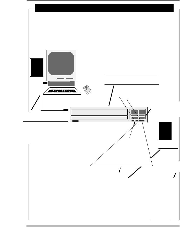
Controlling the CLD-V2400 or CLD-V2600 LD/CD Player
• Level I — Manual Control
Player is controlled using a Remote Control or Barcode Reader or Front Panel Buttons
• Level III — Computer Control
Commands to control the player are sent via RS-232C from a computer or external controller
LEVEL |
(For detailed illustrations of Front and Rear |
|
3 |
||
Panels of the CLD-V2600, See Figures 2-C & |
||
2-D (Chapter 2, page 2-5 & 6); CLD-V2400, |
||
see Figures E & F (Chapter 2, page 2-7). |
||
|
(For Overview of Internal Player Controls, |
|
Computer |
See Appendix H.) |
|
|
Barcode Terminal |
|
|
Remote Sensor |
|
|
Level I - Manual Control |
|
|
Using Front Panel Buttons |
|
|
CLD-V2400 Videodisc Player |
|
|
(Chapter 3) |
Level III - Computer Control via RS-232C
(See Chapter 4)
(For Interface Connections, see Section 2.3.2, pg. 2-10
and Appendix C.)
The CU-V113 remote packaged with
the player, the optional remote control RU-V113 or a
Pioneer barcode reader, can be wired to the player via the Barcode
Terminal on the front panel. They can also send infrared signals to the player via the remote sensor. (See Section 3.2.2, pg. 3-4)
LEVEL
1
Using The Remote
Control Unit
(Chapter 3)
Using the Barcode Reader
(Chapter 3)
|
|
|
|
• |
|
|
|
|
|
|
|
|
|
|
|
|
|
|
|
|
|
|
|
|
|
|
|
|
|
|
|
|
|
|
|
|
7 |
8 |
9 |
|
|
|
4 |
5 |
6 |
|
|
|
1 |
2 |
3 |
|
UC-V108BC |
0 |
|
|
|
|
|
|
CU-V113 |
|
|
||
|
|
|
|
|
|
UC-V109BC
Figure 1-A
1-4 |
TP 117 v. 2.0 • 12/93 CLD-V2600 / 2400 Level I & III User’s Manual |

CLD-V2600 / 2400 Level I & III • Chapter One
Level I — Manual Control
In Level I, the player is controlled by using Remote Control Buttons on the CU-V113 or the RU-V103, by scanning original LaserBarcodes, extended LaserBarcode 2 barcodes, or Barcode CD barcodes, or by using the Front Panel Buttons. Manual Control (Level I) allows simple control of the player using such commands as Play, Stop, Still, Step Forward, etc.
Barcode Terminal
Remote Sensor
LEVEL |
1 CLD-V2400 Videodisc Player |
See
Front Panel Buttons described below
Power ON/OFF
Remote Control Units
The CU-V113 remote control unit packaged with the player, or the optional remote control RU-V103, can be used to control the player. The remote control sends an infrared signal to the player’s remote sensor, or it sends signals via a wired connection to the Barcode Terminal on the front of the player.
wired connection
Infrared signal
•
7 8 9
4 5 6
1 2 3
0
CU-V113
Barcode Reader
A Pioneer Barcode Reader, the UC-V108BC or the
UC-V109BC, can be used to send an infrared signal to the player via the remote sensor. It can also send a signal via a wired connection through the Barcode Terminal on the front of the player.
UC-V108BC UC-V109BC
OPEN /CLOSE |
CLD-V2400 Front Panel Buttons |
|
|
|
|||||||||||
Opens and closes disc tray. |
|
||||||||||||||
|
|
|
|
|
|
|
|
|
|
|
|
|
|
|
|
PLAY |
|
|
|
|
|
|
|
|
|
|
|
|
PLAY |
||
STOP |
|
|
|
|
|
|
|
|
|
||||||
Spins-up & plays videodisc. |
|
OPEN / CLOSE |
|
|
|
|
|
|
|
|
|
|
|
SKIP Chapter/Track |
|
|
|
|
|
|
|
|
|
|
|
|
|
||||
SKIP |
|
|
|
|
|
|
|
|
|
|
|
|
|
|
Forward & Reverse |
Forward & Reverse |
|
|
|
|
|
|
|
|
|
|
|
|
|
|
|
Skips forward or backward |
by chapters (LD) or |
|
|
|
|
|
|
|
|
|
|
|
|
|
SCAN |
|
|
|
|
|
|
|
|
|
|
|
|
|
|||
tracks (CD). |
|
|
|
|
|
|
|
|
|
|
|
|
|
|
|
|
|
|
|
|
|
|
|
|
|
|
|
|
|
Forward & Reverse |
|
SCAN |
|
|
|
|
|
|
|
|
|
|
|
|
|
|
|
Forward & Reverse |
|
|
|
|
|
|
|
|
|
|
|
|
|
|
|
|
|
|
|
|
|
|
|
|
|
|
|
|
|
|
|
|
|
Barcode Terminal |
|
|
Remote Sensor |
|
|
|
|
||||||
Moves rapidly forward or backward through |
|
|
|
|
|
||||||||||
|
|
|
|
|
|
|
|
|
|
|
|
|
|
||
|
|
|
|
|
|
|
|
|
|
|
|
|
|
||
material on a disc. |
|
|
|
|
|
|
|
|
|
|
|
|
|
|
|
POWER ON/OFF |
CLD-V2600 Front Panel Buttons, Details |
STOP- |
|
|
|||
|
|
|
|
OPEN/ |
PAUSE |
PLAY |
|
Powers the player ON / OFF. This button is |
|
|
|
|
|||
Remote Sensor |
Standby |
Barcode Terminal Display |
CLOSE |
|
|
||
on the lower left side of the front panel. |
|
|
|||||
|
|
|
|
|
|
|
|
PAUSE |
|
|
|
|
|
|
|
Pauses playback, presents a squelch screen. |
|
|
|
|
|
|
|
STILL FORWARD & REVERSE |
|
|
|
|
|
SCAN |
|
Holds a still image on CAV, and steps forward |
|
|
|
|
|
|
|
or back one frame at a time. |
|
|
|
|
|
|
|
DISPLAY |
|
|
|
|
|
|
|
Displays the Chapter, Frame or Time number |
Headphone jack & Vol. |
DISPLAY |
STEP FWD/REV |
SKIP FWD/REV |
|
||
on the screen, indicating location on the disc. |
|
||||||
POWER ON/OFF |
|
|
|
|
|
|
|
|
|
|
|
|
|
|
|
For information about using the Front Panel Buttons, the Remote Control Unit
(CU-V113 or RU-V103) or a Pioneer Barcode Reader for Manual Control (Level I Control) of the CLD-V2600 or the CLD-V2400, see Chapter 3.
Figure 1-B
CLD-V2600 /2400 Level I & III User’s Manual TP 117 v. 2.0 • 12/93 |
1-5 |
Chapter One • CLD-V2600 / 2400 Level I & III
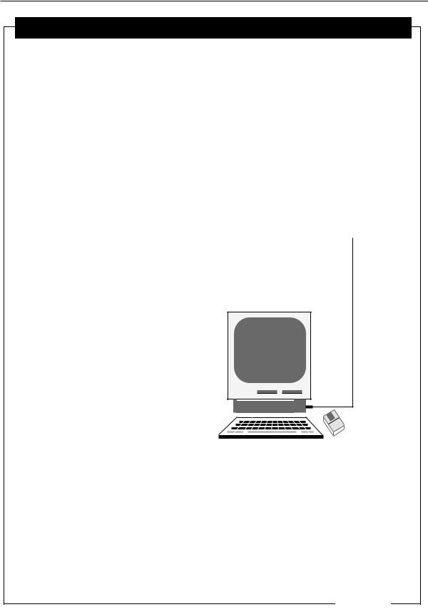
Level III — External Computer Control
Level III programs are used to control the player from an external computer attached to the player’s RS-232C port. The player’s Level III mnemonic command set is used to develop interactive programs for the CLD-V2600 or the CLD-V2400. (See Section 4.4 on pages 4-5 and 4-6 or Appendix A for the list of mnemonic commands available.) Level III mnemonic commands are also used to control the LD-V8000, the LD-V4400, and the LD-V2200 (NTSC players), LD-V4200 (discontinued NTSC player), the CLD-V2300D and the LD-V4300D (NTSC/PAL players), and the LD-V4100 (PAL player). See Technical Bulletin #143 , Comparative Mnemonic Command Chart. Level III is often used when a program designer wants users to access a large database from a computer, along with video and audio material on a disc. Level III requires that a computer be connected to every player. A file server may be used to network the computers at the various workstations.
LEVEL |
|
|
|
|
|
|
|
|
|
|
|
|
|
|
|
|
|
|
|
|
|
|
|
|
|
|
|
3 |
|
CLD-V2400 Videodisc Player |
|
|
|
|
|
|
|
|
|
||
|
|
|
|
|
|
|
|
|
|
|
|
RS-232C cable to |
|
|
|
|
|
|
|
|
|
|
|
|
|
RS-232C port on |
|
|
|
|
|
|
|
|
|
|
|
|
|
back of player |
|
|
|
|
|
|
|
|
|
|
|
|
|
|
|
|
|
|
|
|
|
|
|
|
|
|
|
|
|
|
|
|
|
|
|
|
|
|
|
|
|
|
|
Level III programs are developed on a computer. Commands are sent to the player directly from the computer to control a specific videodisc or compact disc. In addition to providing interactive control of the player, the computer can also send graphic overlays to the video monitor, provide access to a computer database, etc.
(See Chapter 4 and Appendix A.)
Computer
For detailed information about Computer Control of the CLD-V2600 and the CLD-V2400, see Chapter 4 and Appendix A of this manual.
Figure 1-C
|
|
|
|
|
|
|
|
|
1-6 |
TP 117 v. 2.0 • 12/93 CLD-V2600 / 2400 Level I & III User’s Manual |
|
|
|
|
|

CLD-V2600 / 2400 Level I & III • Chapter One
1.4 Chapter Highlights
This manual provides:
•An overview of player operating processes.
•How to customize player functions by using Function Switches and On-Screen Status Displays.
•Specific information about Manual and Computer control.
It is divided into chapters providing the following information:
Chapter One — Introduction
This chapter describes the scope and overview of the Pioneer CLD-V2600 & CLD-V2400 Level I and III User’s Manual and explains how information is organized. It also defines Level I, II, III as they relate to specific hardware configurations, and illustrates Level I and III configurations.
Chapter Two — Operational Basics
This chapter gives an overview of the player’s internal operating processes, describing Operating Modes and Active States, and the front panel indicators. It also describes player interfaces: The infrared sensor, used to receive infrared barcode and remote control signals; the barcode terminal, used to receive wired barcode and remote control signals; and the RS-232C serial interface.
There are also illustrations of the front and rear panels of both players showing the front panel LEDs and buttons; rear function switches, audio output jacks, video output jacks and the RS-232C port.
There is also a section describing the player’s Function Switches and the On-Screen Status Displays.
Chapter Three — Manual Control — Level I
This chapter describes the player’s front panel buttons, the remote control buttons on the CU-V113 & RU-V103, and features of the Pioneer barcode readers. All of these can be used for Level I control of the CLD-V2600 or the CLD-V2400 while playing LDs or CDs.
Chapter Four — External Computer Control — Level III
This chapter explains how commands are sent to the CLD-V2600 and the CLD-V2400 from an external computer to control playback of LDs or CDs. It also describes error messages that may be returned, the default settings, a basic list of Level III commands and descriptions of each command.
CLD-V2600 / 2400 Level I & III User’s Manual TP 117 v. 2.0 • 12/93 |
1-7 |

Chapter One • CLD-V2600 / 2400 Level I & III
Commands are described by categories: Player Control Commands, Player Control Switch Commands, Display Control Commands, Request Commands, Communication Control Commands, Register Control Commands, and Input Device Commands.
For additional information see the attached Appendices:
Appendix A Level III commands on the CLD-V2600 & CLD-V2400
Appendix B Remote Control Units — CU-V113 &RU-V103
Appendix C CLD-V2600 & CLD-V2400 Interface Cable Specifications
Appendix D LaserBarcode™, LB2 Commands & Logo
Appendix E Barcode CD™ Standard Commands & Barcode CD Logo
Appendix F Barcode Formats and Player Compatibility
Appendix G Pioneer Barcode Readers — UC-V108BC & UC-V109BC
Appendix H CLD-V2600 & CLD-V2400 Internal Player Controls
Appendix I CLD-V2600 & CLD-V2400 Internal Player Registers
Appendix J Additional Notes
Further questions should be referred to:
Pioneer New Media Technologies, Inc.
Engineering & Product Development Engineering Support
600 East Crescent Avenue
Upper Saddle River, New Jersey 07458-1827 USA 201/327-6400
FAX: 201/327-9379
East Coast Engineering Support:
201/327-6400
West Coast Engineering Support:
310/952-2111
1-8 |
TP 117 v. 2.0 • 12/93 CLD-V2600 / 2400 Level I & III User’s Manual |
2.Operational Basics
2.1Internal Operations
2.2Player Indicators
2.3Interfaces
2.4Function Switches
2.5On-Screen Displays in Manual Mode
CHAPTER
2
CLD-V2600
& CLD-V2400
LEVEL I & III
USER’S MANUAL
Programmer’s Reference Guide
CLD-V2600 / 2400 Level I & III User’s Manual TP 117 v. 2.0 • 12/93

CLD-V2600 / 2400 Level I & III • Chapter Two
2 Operational Basics
This chapter provides an overview of the player’s internal operations — Operating Modes and the player’s Active States; diagrams of the player’s Front and Rear Panels; a description of the player’s Front Panel Indicators, Player Interfaces, and Function Switches. Before developing or presenting programs on the CLD-V2600 or CLD-V2400 the user should read this chapter and become familiar
with the introductory concepts, illustrations and operational basics. (See Appendix H,
CLD-V2600 & CLD-V2400 Internal Player Controls, for more details.)
2.1 Internal Operations
The player’s internal operating processes are classified into two groups: Operating Modes indicating player operation status, and Active States indicating player processing status.
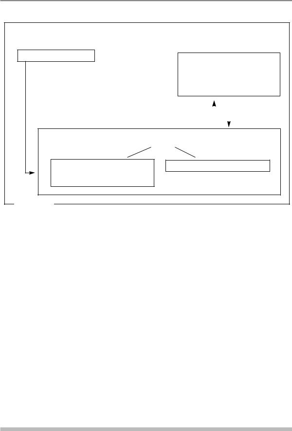
2.1.1 Operating Modes
The CLD-V2600 and the CLD-V2400 have the following two Operating Modes:
Normal Control Mode and Test Mode. (See Figure 2-A on next page.)
These modes are defined as follows:
1) Normal Control Mode
When the player’s power is turned on, the player enters Normal Control Mode. In this mode, the player can be controlled by pressing buttons on the front panel, by pressing buttons on the remote control unit, by sending commands via the Pioneer barcode reader, or by sending commands from a computer via the RS-232C connector.
2) Test Mode
The Test Mode is set in Register C under computer control. (See page 4-43) It is used for player maintenance and management. This mode is used primarily by Authorized Service Company (ASC) personnel to determine key part numbers of the player and to service the player. Generally, the player is not controlled in this mode. Turn ON (1) bit 7 of Register C via computer control to make the CLD-V2600 or the CLD-V2400 enter this mode. Turn OFF (0) bit 7 of Register C to change the operating mode from Test Mode to Normal Control Mode.
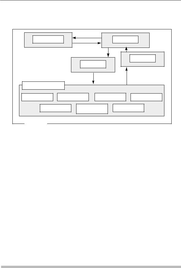
2.1.2 Active States
CLD-V2600 & CLD-V2400 processing is performed within several distinct Active States. When a command is executed, the Active State changes inside the player. If you consider player processing as a series of events within the Active States listed below, it is easier to understand the effects of various commands. The player’s five main Active States are:
CLD-V2600 / 2400 Level I & III User’s Manual TP 117 v. 2.0 • 12/93 |
2-1 |
Chapter Two • CLD-V2600 / 2400 Level I & III
Operating Modes
P O W E R — O N
Test Mode
Turn ON (1) Bit 7 of Reg C. Not required for normal player operation; used primarily by service center personnel for servicing the player.
|
|
|
|
|
|
REG. C |
|
|
|
|
REG. C |
|
|||||
BIT 7=1 |
|
|
|
|
BIT 7=0 |
|
|
|
|
|
|
|
|
|
|
|
|
|
|
|
|
|
|
Normal Control Mode |
|
|
using |
Front Panel Buttons |
R S — 2 3 2 C |
Remote Control |
|
LaserBarcode Control |
|
Figure 2-A |
|
•Door Open
•Park
•Spin Up
•Random Access
•Spin Down
The player is in Door Open before the disc is loaded into the disc tray. After the door is closed, the player enters Park. When a START or PLAY command is input while the player is in Park, the disc starts rotating and the player enters Spin Up. When the player is ready to play images, it enters Random Access. Random Access is further divided into Play, Still, Scan, Pause, Multi-Speed, Skip (Chapter and Track) and Search.
When a REJECT command is received, the player enters Spin Down Mode. Image playback stops immediately, and disc rotation is gradually stopped, then the player enters Park. Figure 2-B, on the next page, describes how the active states change within the player.
2-2 |
TP 117 v. 2.0 • 12/93 CLD-V2600 / 2400 Level I & III User’s Manual |
CLD-V2600 / 2400 Level I & III • Chapter Two
Transitions Between Active States
DOOR OPEN |
|
OPEN |
PARK |
|
|
||
|
|
CLOSE |
|
|
|
|
SPIN DOWN |
|
|
SPIN UP |
|
RANDOM ACCESS |
|
|
|
PLAY |
STILL |
SCAN |
PAUSE |
MULTI-SPEED |
SKIP |
SEARCH |
|
|
|
(Chapter/Track) |
|
Figure 2-B |
|
|
|
2.2 Player Indicators for the CLD-V2400 & CLD-V2600
The CLD-V2400 has four indicator lights on the front panel. These four indicators are explained below. (See diagram of CLD-V2400’s Front Panel, Figure 2-F, on page 2-7.)
Digital Sound (green) — This indicator lights up after power is turned on, except when a disc with no digital audio is in the disc tray.
Disc Set (green) — The Disc Set indicator lights up when a disc is loaded in the player.
Play/Standby (green)— This indicator flashes when the disc begins to spin up, when disc rotation stops, during a search and while in the lead-out area. It also lights up during playback.
Key Lock Indicator (red) — The Key Lock indicator lights up if a computer command has been sent to the player to lock out the front panel buttons, the barcode reader and remote control buttons, preventing them from being used during execution of a Level III program.
The CLD-V2600 has an illuminated front panel display and a Standby light that indicates the player is plugged in, but not powered on. It also has a Key Lock light, indicating when the front panel buttons or remote control or LaserBarcode Control have been locked out under Level III, RS-232C control. Please see Figure 2-C on the next page for details of the illuminated display window on the front panel. Also see Figure 2-D on page 2-5 for other details on the Front Panel.
CLD-V2600 / 2400 Level I & III User’s Manual TP 117 v. 2.0 • 12/93 |
2-3 |
Chapter Two • CLD-V2600 / 2400 Level I & III
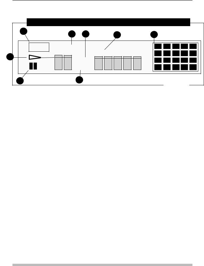
CLD-V2600 — Front Panel Illuminated DISPLAY WINDOW
1 |
5 |
6 |
7 |
8 |
|
D I G I TA L |
|
|
|
S O U N D |
CHP-TRK |
|
FR-TM |
|
|
||
2 |
|
REP |
|
|
|
||
|
|
1 |
/ L |
|
|
2 |
/ R |
3 |
4 |
Figure 2-C
1.DIGITAL SOUND INDICATOR: This indicator lights when the disc being played has digital audio and when the digital audio signal is output from a LaserDisc. When analog audio is selected from a disc with digital audio, this indicator does not light.
2.PLAY: This indicator lights during playback and blinks during search. The Chapter-Track or Frame-Time numbers to the right of this indicator, show the current playback location on the disc.
3.PAUSE INDICATOR: This indicator lights when the player is in Pause Mode.
4.1/L, 2/R INDICATOR: Indicates the audio output channel.
5.CHP/TRK INDICATOR: Indicates the Chapter number on an LD, or Track number on a CD Audio disc.
6.REP INDICATOR: This lights when Repeat Chapter or Repeat Side has been selected.
7.FRM-TM INDICATOR: Indicates the Frame number on a CAV LaserDisc or Time number on a CLV LaserDisc or the Time number on a CD Audio disc. (You will notice that short words appear in this location to indicate player status. NO DISC: “No disc in tray”; OPEN: “Opening disc tray”; CLOSE: “Closing disc tray”; DISC: “Spinning up disc”; LD: “LaserDisc is in the tray”; CD: “CD Audio disc is in tray”.)
8.VISUAL CALENDAR: If a Table of Contents (TOC) is present on an LD, all of the Chapter numbers recorded on the disc light up as the disc starts and if the disc contains more than 19 chapters, the > indicator lights in the last square. After a chapter has finished playing, the corresponding number goes out. When an LD without a TOC is played, only the current chapter being played lights up. All CDs have TOCs, so all of the track numbers recorded on the disc light up as the disc starts. If the CD has more than 19 tracks, the > indicator lights in the last square. After a track has finished playing, the corresponding number goes out.
2-4 |
TP 117 v. 2.0 • 12/93 CLD-V2600 / 2400 Level I & III User’s Manual |
CLD-V2600 / 2400 Level I & III • Chapter Two
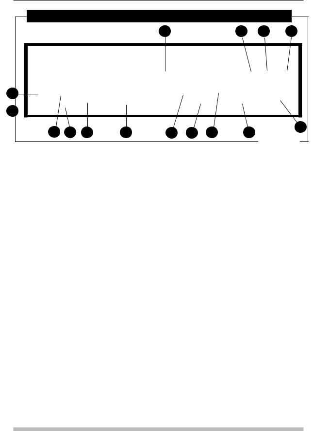
CLD-V2600 — Front Panel View
1 |
2 |
3 |
4 |
5
6 
7 |
8 |
9 |
10 |
11 |
12 |
13 |
15 |
14 |
Figure 2-D
1DISC TRAY: Press the STOP OPEN /CLOSE button to open the door and eject the tray.
2STOP OPEN CLOSE BUTTON: Press this button to open and close the disc tray. Place a disc on the disc tray then press this button to retract the disc tray into the player. Press this button while a disc is playing to stop playback. Press it again to eject the tray.
3PAUSE BUTTON: Press this button to stop playback temporarily. To resume playback, press the PLAY button.
4PLAY BUTTON: Press this button to start playback or to resume ordinary playback from a still image or from pause mode.
5POWER BUTTON: Press this button to turn the power ON and OFF.
11KEY LOCK INDICATOR: This indicator lights up when the Key Lock command is sent from a computer or external control unit. When it is lit, front panel buttons other than the power switch are disabled. Also, signals from a remote control unit or optional LaserBarcode reader are not accepted.
12DISPLAY BUTTON: Pressing this button displays the chapter (CAV or CLV), track (CD Audio), frame (CAV) or time number (CLV or CD Audio) on the TV screen or video monitor. Pressing it again removes the numbers from display. NOTE: With CDs, the track, index and elapsed time will be displayed when this button is pressed while the absolute time is displayed.
13STILL / STEP BUTTONS: Press either of these buttons to produce a still video image. Pressing the STEP FWD button again moves the image forward one frame at a time. STEP REV presents each preceding frame. (CAV discs only. These buttons do not function with CLV discs.)
6HEADPHONE JACK & VOLUME CONTROL:
Plug a headphone set into this jack, use the “LEVEL” knob to control the volume.
7REMOTE SENSOR: Infrared commands from the remote control unit or from a wireless LaserBarcode reader are received here.
8STANDBY INDICATOR: This indicator lights up when the power is off.
9BARCODE JACK: Connect a Pioneer LaserBarcode Reader (UC-V108BC or UC-V109BC) via this jack.
10DISPLAY WINDOW INDICATORS: See page 2-4 for details.
14SKIP BUTTONS: Press the SKIP FWD button to advance to the next chapter or track and start playback. Press the SKIP REV button once to return the player to the beginning of the current chapter or track. Pressing this button several times before pictures or audio is played, will search back a corresponding number of chapters or tracks.
15SCAN CONTROL: Rotate the SCAN CONTROL dial to advance or reverse playback rapidly. On CLV discs, slightly rotate the dial for a clear picture scan. Rotate the dial further for a normal CLV Scan. On CAV discs, rotate the dial slightly to play back the disc at 9x normal speed. Rotate fully to play back at 32x normal speed. Both CAV scan speeds present clear picture scan. (See page 3-3.)
CLD-V2600 / 2400 Level I & III User’s Manual TP 117 v. 2.0 • 12/93 |
2-5 |
Chapter Two • CLD-V2600 / 2400 Level I & III
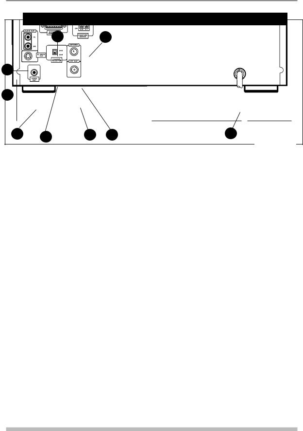
CLD-V2600 — Rear Panel View
1 |
2 |
3
4 
5 |
6 |
7 |
8 |
9 |
Figure 2-E
1.INTERFACE CONNECTOR RS-232C (D-SUB 15 pin): This provides a serial interface connection to a computer or controller. (See Appendix C of this Manual for cable descriptions, or Pioneer Product Information Bulletin #6.)
2.FUNCTION SWITCHES: Switch 1 sets Load Start /Power On Start ON or OFF. Switch 2 sets Baud Rate to 1200 or 4800. Switch 3 sets the Squelch on the monitor to Black or Blue. Switch 4 is not used. The factory default sets all switches OFF (in the UP position): Load Start /Power On Start is OFF; Baud Rate is 4800; Squelch is set to Blue. If the function switch settings are changed, initialize the player by turning the power OFF and ON again.
3.AUDIO OUT TERMINALS (RCA Jacks): These terminals output the audio signals from LaserDiscs or Compact Discs. Connect them to the Audio IN jacks on the back of a video monitor. Or connect them to the LD or AUX input terminals of your stereo amplifier. Do not connect them to your amplifier PHONO input. (Two Audio cables are supplied with the player.)
4.S-VIDEO OUT TERMINAL: The player can be connected via this connector to an AV monitor or television equipped with an S-VIDEO INPUT terminal. The Audio connections from Audio OUT on the player to Audio IN on the monitor must also be made.
5.VIDEO OUT TERMINAL (RCA Jack): This terminal outputs an NTSC video signal and is used for connecting the player to a color video or TV monitor that has a video input jack. (A video cable is supplied with the player.)
6.CHANNEL SELECTOR (CH 3 / CH 4): This switch changes the channel of the internal RF converter. Set this to the channel that is not used for TV broadcasts in your area.
7.VHF OUT TERMINAL (75 Ω F-type jack): Connect this terminal to the VHF antenna terminal of your TV set. (An Antenna Cable is supplied with the player.)
8.ANTENNA TERMINAL (75 Ω F-type jack): Connect the coaxial cable (75Ω) from the VHF TV antenna to this terminal. (An adapter to connect the coaxial cable is supplied with the player.)
9.SAFETY POWER CORD: This is a 3-line power cord with a 3-pronged power plug. Insert the power plug into a wall outlet (120V, 50/60 Hz). Make sure the wall outlet has a ground terminal. Do not defeat the ground plug by using an inappropriate connector.
2-6 |
TP 117 v. 2.0 • 12/93 CLD-V2600 / 2400 Level I & III User’s Manual |
CLD-V2600 / 2400 Level I & III • Chapter Two
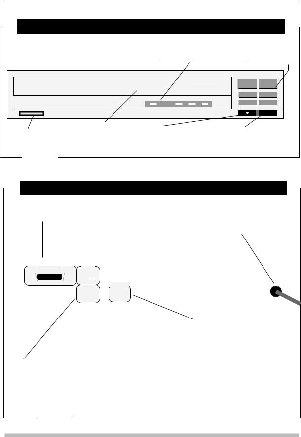
CLD-V2400 — Front Panel View
LED Indicators
Front Panel
Digital Sound, Disc Set, Play Standby, Key Lock
Control
Buttons
CD CDV LD Player |
CLD-V2400 |
|
LaserDisc |
|
|
|
|
|
|
|
|
|
|
|
|
|
|
|
|
|
|
|
|
|
|
|
|
Disc Tray Door |
|
|
|
|
|
|
|
|
Barcode Terminal for wired connection to |
Remote Sensor for |
|||||
|
Power ON/OFF |
|
|
|
|||||
|
|
|
|
||||||
|
|
|
|
Pioneer Barcode Reader or Remote Control |
receiving infrared signals |
||||
|
|
|
|
|
|
||||
|
|
|
|
|
|
Unit (CU-V113 or RU-V103). |
from the barcode reader or |
||
|
|
|
|
|
|
|
remote control unit. |
||
Figure 2-F
CLD-V2400 — Rear Panel View
Interface Connector / RS-232C Port
D-SUB 15 pin. Used for serial interface connection to a computer or a controller. See page 2-10 for details.
Function Switches
Function Switch 2 is on the left, and Switch 1 is on the right.
See Section 2.4, page 2-13 of this manual to set player functions.
Power Cord Connects to a wall outlet (120V AC, 60 Hz). Note: For safety reasons, this product uses a 3-line power cord and a 3-pronged power plug. Make sure to insert the power plug into a wall outlet with a ground terminal.
|
|
|
|
|
|
|
|
|
|
|
|
|
|
|
|
|
|
|
|
|
|
|
|
|
INTERFACE |
|
|
|
|
|
|
|
|
|
|
|
|
|
|
|
|
|
|
|
|
|
|
|
|
|
|
|
|
|
|
|
|
|
|
|
|
|
|
|
|
|
|
|
|
|
|
|
|
|
|
|
|
|
|
|
|
|
|
|
|
|
FUNCTION |
|
|
|
|
|
|
|
|
||||
|
|
|
|
|
CONNECTOR |
|
|
SWITCHES |
|
|
|
|
|
|
|
|
|||
|
|
|
• |
••••••••••••••• |
• |
|
OFF |
|
|
|
|
|
|
|
|
|
|
||
|
|
|
|
ON |
|
|
|
|
|
|
|
|
|
|
|||||
|
|
|
|
|
|
|
|
|
oVideo.Audio |
|
|
|
|
|
|||||
|
|
|
|
|
|
|
|
|
•1L 2R• |
|
|
|
|
|
|
|
|||
|
|
|
|
|
|
|
|
|
AUDIO OUT |
|
|
• |
|
|
|
||||
|
|
|
|
|
|
|
|
|
|
|
|
|
|
||||||
|
|
|
|
|
|
|
|
|
|
RF Adapter Output |
|
|
|
|
|||||
|
|
|
|
|
|
|
|
|
|
|
|
|
|
|
|
|
|
|
|
|
|
|
|
|
|
|
|
|
|
|
|
|
|
|
|
|
|
|
|
|
|
|
|
|
|
|
|
|
|
|
|
|
|
|
|
|
VHF Adapter Output Terminals These connect to |
||
|
|
|
|
|
|
|
|
|
|
|
|
|
|
|
|
|
the RF modulator (supplied with the unit) that is used when |
||
|
|
|
|
|
|
|
|
|
|
|
|
|
|
|
|
|
connecting to a normal TV. Note that TV audio will be |
||
|
|
|
|
|
|
|
VIDEO OUTPUT Terminal (One RCA |
||||||||||||
|
|
|
|
|
|
|
monophonic when using the RF modulator. The RF |
||||||||||||
|
|
|
|
|
|
|
Jack) This terminal is connected to the video |
||||||||||||
|
|
|
|
|
|
|
modulator uses DC 5V power supplied from the player. |
||||||||||||
|
|
|
|
|
|
|
input jack of a color video monitor. |
||||||||||||
|
|
|
|
|
|
|
When the player is powered on, player audio & video signals |
||||||||||||
|
|
|
|
|
|
|
|
|
|
|
|
|
|
|
|
|
|||
|
|
|
|
|
|
|
|
|
|
|
|
|
|
|
|
|
are output by the RF Modulator. When the player is turned |
||
|
|
|
|
|
|
|
|
|
|
|
|
|
|
|
|
|
|||
AUDIO OUTPUT Terminals (Two RCA Jacks) These |
off, the modulator will pass an external antenna signal |
||||||||||||||||||
terminals output the audio of LaserDiscs and CDs. Connect them |
through to the TV. |
|
|
to the LD or AUX input terminals of your stereo amplifier. Do NOT |
|
connect these terminals to your amplifier PHONO input. |
|
Note: The VHF ADAPTER OUTPUT terminals are shared with the VIDEO OUT Terminal. Therefore, either a monitor or a TV can be connected, but not both at the same time.
Figure 2-G
CLD-V2600 / 2400 Level I & III User’s Manual TP 117 v. 2.0 • 12/93 |
2-7 |
Chapter Two • CLD-V2600 / 2400 Level I & III
2.3 Interfaces
This section describes the player interfaces that receive control signals:
•The remote sensor receives infrared signals from the CU-V113 or RU-V103 remote control units or a Pioneer barcode reader. (See Section 2.3.1, below for details.)
•The Barcode Terminal receives signals from a wired connection to either the remote control unit or the barcode reader. (See Section 2.3.1, page 2-9, for details.)
•The RS-232C port receives signals from an external computer via the appropriate RS-232C cable. (See Section 2.3.2, page 2-10.)
Please see the Front and Rear View diagrams of the players to locate each interface:
•CLD-V2600 — Figures 2-D and Figure 2-E on page 2-5 & 2-6.
•CLD-V2400 — Figures 2-F and Figure 2-G on page 2-7.
2.3.1 Remote Sensor and the Barcode Terminal
The remote sensor receives input via infrared signal and the Barcode terminal receives input via a wired connection. Both the remote sensor and the Barcode Terminal can receive signals from either a Pioneer Barcode Reader or from the remote control unit. Both Barcode and remote control commands are transmitted in serial data streams. Note: The infrared sensor and the Barcode Terminal cannot be used simultaneously.
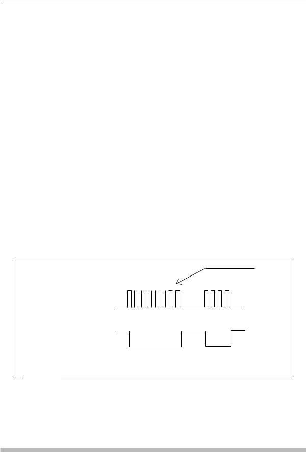
Carrier 48KHz |
Signal received by the |
infrared receiver |
Demodulated infrared |
signal |
Waveform of Infrared Remote Control Signal |
Figure 2-H |
The remote sensor receives the RCU signals on a 48-KHz carrier, removes the carrier, shapes the waveform, and outputs the shaped waveform. See Figure 2-H. A stereo or mono mini-plug cable (Figure 2-I, next page) can be used to input a signal to the Barcode terminal, when a wired connection from the remote control unit or the Barcode Reader is made.
2-8 |
TP 117 v. 2.0 • 12/93 CLD-V2600 / 2400 Level I & III User’s Manual |
CLD-V2600 / 2400 Level I & III • Chapter Two
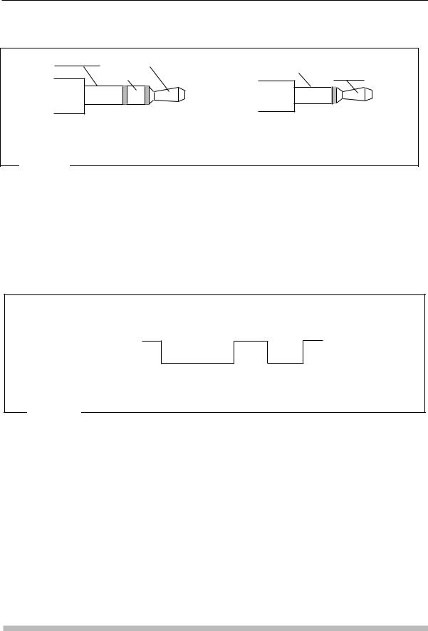
GND Switch |
RCU/Barcode Data |
|
RCU/ |
|
|
GND Switch |
Barcode |
|
Not Used |
|
Data |
Stereo Mini-Plug |
Mono Mini-Plug |
||
|
Barcode Terminal Plugs |
|
|
Figure 2-I |
|
|
|
The CU-V113 or RU-V103* remote control can each be used with a cable that has a stereo or mono mini-plug on each end. The Barcode Reader is packaged with a wire that has a stereo mini-plug on the end that connects to the reader and a mono miniplug on the end that connects to the player. RCU or Barcode Reader signals transmitted via cable are input in the shape of the waveform shown in Figure 2-J, below.
* Neither the CU-V113 nor the RU-V103 remote control is packaged with a cable to connect to the Barcode Terminal.
Signal carried by wired connection from RCU or Barcode Reader
Waveform of Wired Remote Control Signal
Figure 2-J
The Ground Switch connection is used to make either the remote sensor or the Barcode Terminal active. The Barcode Terminal becomes active when the signal is low (or is closed). The remote sensor becomes active when the signal is high (or is open).
RCU input is decoded by the RCU Decoder. See Figure 2-K on the next page and
Appendix H, CLD-V2600 & CLD-V2400 Internal Player Controls for details; page H-3 for Control Block Diagram.
The RCU Decoder interprets both commands and responses from an input device. NOTE: The player’s RCU decoder cannot simultaneously decode signals received via remote sensor and Barcode Terminal.
CLD-V2600 / 2400 Level I & III User’s Manual TP 117 v. 2.0 • 12/93 |
2-9 |
 Loading...