


INSTALLATION MANUAL
AVH-P7600DVD
This product conforms to CEMA cord colors.
Le code de couleur des câbles utilisé pour ce produit est conforme à CEMA.
D’INSTALLATION MANUEL |
Nederlands Italiano Français Deutsch Français English |
|
|
Contents |
|
Connecting the Units ................................ |
1 |
Connecting the system ...................................... |
3 |
Connecting the power cord (1) .......................... |
4 |
Connecting the power cord (2) .......................... |
5 |
When connecting to separately sold power |
|
amp ............................................................ |
7 |
When connecting with a rear view camera ...... |
9 |
When connecting the external video |
|
component and the display ...................... |
11 |
Attaching the noise filters .............................. |
12 |
Installation ................................................ |
13 |
Installing the hide-away unit .......................... |
13 |
DIN Front/Rear-mount .................................... |
14 |
DIN Front-mount ............................................ |
14 |
DIN Rear-mount .............................................. |
15 |
Fixing the front panel ...................................... |
16 |
Installing the remote control unit .................... |
16 |
WARNING:
•To avoid the risk of accident and the potential violation of applicable laws, the front DVD or TV (sold separately) feature should never be used while the vehicle is being driven. Also, Rear Displays should not be in a location where it is a visible distraction to the driver.
•In some countries or states the viewing of images on a display inside a vehicle even by persons other than the driver may be illegal. Where such regulations apply, they must be obeyed and this unit’s DVD features should not be used.
Connecting the Units
CAUTION:
•PIONEER does not recommend that you install or service your display yourself. Installing or servicing the product may expose you to risk of electric shock or other hazards. Refer all installation and servicing of your display to authorized Pioneer service personnel.
•Secure all wiring with cable clamps or electrical tape. Do not allow any bare wiring to remain exposed.
•Do not drill a hole into the engine compartment to connect the yellow lead of the unit to the vehicle battery. Engine vibration may eventually cause the insulation to fail at the point where the wire passes from the passenger compartment into the engine compartment. Take extra care in securing the wire at this point.
•It is extremely dangerous to allow the display lead to become wound around the steering column or gearshift. Be sure to install the display in such a way that it will not obstruct driving.
•Make sure that wires will not interfere with moving parts of the vehicle, such as the gearshift, parking brake or seat sliding mechanism.
•Do not shorten any leads. If you do, the protection circuit may fail to work properly.
1
Note:
•This unit is for vehicles with a 12-volt battery and negative grounding. Before installing it in a recreational vehicle, truck, or bus, check the battery voltage.
•To avoid shorts in the electrical system, be sure to disconnect the ≠ battery cable before beginning installation.
•Refer to the owner’s manual for details on connecting the power amp and other units, then make connections correctly.
•Secure the wiring with cable clamps or adhesive tape. To protect the wiring, wrap adhesive tape around them where they lie against metal parts.
•Route and secure all wiring so it cannot touch any moving parts, such as the gear shift, handbrake and seat rails. Do not route wiring in places that get hot, such as near the heater outlet. If the insulation of the wiring melts or gets torn, there is a danger of the wiring short-circuiting to the vehicle body.
•Don’t pass the yellow lead through a hole into the engine compartment to connect to the battery. This will damage the lead insulation and cause a very dangerous short.
•Do not shorten any leads. If you do, the protection circuit may fail to work when it should.
•Never feed power to other equipment by cutting the insulation of the power supply lead of the unit and tapping into the lead. The current capacity of the lead will be exceeded, causing overheating.
•When replacing the fuse, be sure to only use a fuse of the rating prescribed on the fuse holder.
•Since a unique BPTL circuit is employed, never wire so the speaker leads are directly grounded or the left and right ≠ speaker leads are common.
•If the RCA pin jack on the unit will not be used, do not remove the caps attached to the end of the connector.
•Speakers connected to this unit must be highpower with minimum rating of 50 W and impedance of 4 to 8 ohms. Connecting speakers with output and/or impedance values other than those noted here may result in the speakers catching fire, emitting smoke, or becoming damaged.
•When an external power amp is being used with this system, be sure not to connect the blue/white lead to the amp’s power terminal. Likewise, do not connect the blue lead to the power terminal of the auto-antenna. Such connection could cause excessive current drain and malfunction.
•To avoid a short-circuit, cover the disconnected lead with insulating tape. Insulate the unused speaker leads without fail. There is a possibility of a short-circuit if the leads are not insulated.
•To prevent incorrect connection, the input side of the IP-BUS connector is blue, and the output side is black. Connect the connectors of the same colors correctly.
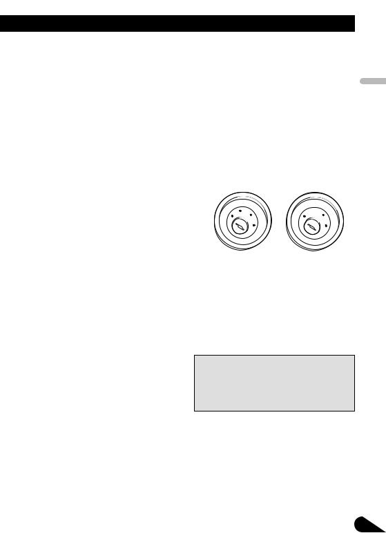
•This unit cannot be installed in a vehicle that does not have an ACC (accessory) position on the ignition switch. (Fig. 1)
|
|
CC |
|
|
|
|
|
|
|
|
|
F |
A |
O |
|
|
|
F |
O |
|
|
|
F |
|
N |
|
N |
|||||
O |
|
|
|
|
O |
F |
|
|
|
|
|
|
|
|
S |
|
|
|
S |
||
|
|
|
|
|
|
|
|
|
||
|
|
|
|
|
T |
|
|
|
|
T |
|
|
|
T |
R |
A |
|
|
|
R |
A |
|
|
|
|
|
|
T |
|
|||
ACC position |
No ACC position |
|||||||||
Fig. 1
•The black lead is ground. Please ground this lead separately from the ground of high-current products such as power amps.
If you ground the products together and the ground becomes detached, there is a risk of damage to the products or fire.
•Cords for this product and those for other products may be different colors even if they have the same function. When connecting this product to another product, refer to the supplied manuals of both products and connect cords that have the
same function.
English
Español
Italiano Français Deutsch
Nederlands
2

Connecting the Units
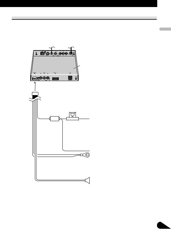
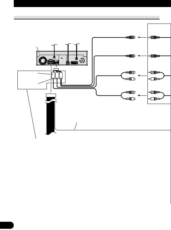
Connecting the system
Yellow |
40 cm |
15 cm |
|
|
||||||
|
|
|
|
(1 ft. 4 in.) |
(5-7/8 in.) |
|
|
|||
|
|
|
|
|
|
|
|
|
|
|
|
|
|
|
|
|
|
|
|
|
|
|
|
|
|
|
|
|
|
|
|
|
26 pin cable
Navigation unit (e.g. AVIC-880DVD) (sold separately)
Black |
Violet |
This product
|
|
30 pin cable (supplied) |
|
|
3 m |
|
|
(9 ft. 10 in.) |
|
Blue |
3 m |
|
|
(9 ft. 10 in.) |
|
IP-BUS input |
Antenna cable (supplied) |
|
Violet |
|
|
(Blue) |
|
|
|
|
|
|
3 m |
|
|
(9 ft. 10 in.) |
|
Hide-away unit |
|
|
(supplied) |
|
|
|
Antenna jack |
|
Black |
21 pin cable (supplied) |
Blue |
|
|
10 cm |
|
|
|
|
|
|
(3-7/8 in.) |
Auto-EQ&TA mic jack |
|
15 cm |
See the operation manual. |
|
|
|
|
(5-7/8 in.) |
|
AV-BUS input (Blue)
IP-BUS cable (supplied with TV tuner)
|
IP-BUS cable |
|
|
|
Multi-CD player |
Black |
Blue |
(sold separately) |
Hide-away TV tuner (e.g. GEX-P6400TV) (sold separately)
AV-BUS cable (supplied |
Black |
with TV tuner) |
Fig. 2
3
Connecting the power cord (1)
Hide-away unit
Fuse holder
Yellow
To terminal always supplied with power regardless of ignition switch position.
Black (ground)
To vehicle (metal) body.
Black ≠
Center speaker
Black/white +
English
Español
Italiano Français Deutsch
Nederlands
Fig. 3
4
Connecting the Units
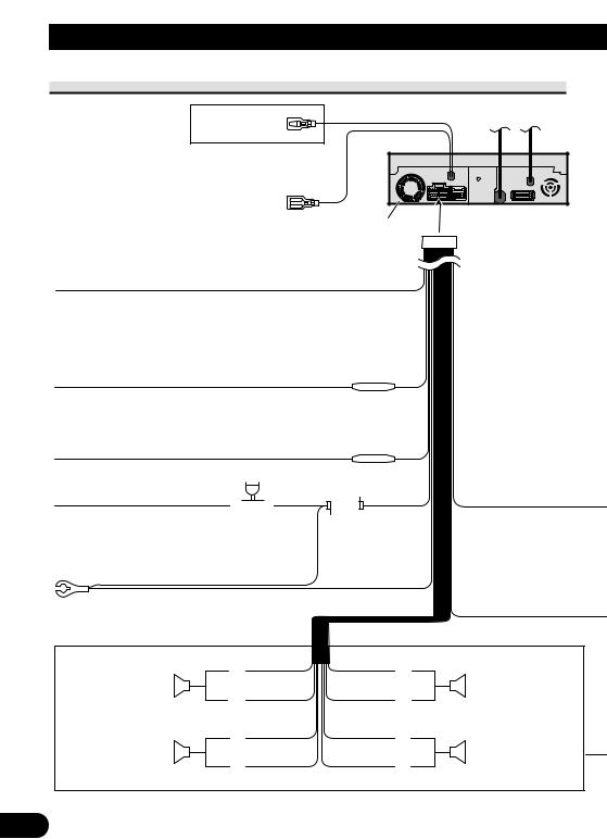
Connecting the power cord (2)
See the section “When
connecting with a rear view Violet/white camera”.
Blue
When the source is selected the tuner, a control
signal is output. To Auto-antenna relay control terminal.
If the car features a glass antenna, connect to the antenna booster power supply terminal (max. 300 mA 12 V DC).
Yellow/black
If you use an equipment with Mute function, wire this lead to the Audio Mute lead on that equipment. If not, keep the Audio Mute lead free of any connections.
Red
To electric terminal controlled by ignition switch (12 V DC) ON/OFF.
This product
Fuse resistor
Orange/white |
|
|
|
|
|
|
Fuse resistor |
|||||||
To lighting switch terminal. |
|
|
|
|
|
|
|
|
|
|
|
|
||
|
|
|
|
|
|
|
|
|
|
|
|
|||
Yellow |
|
|
|
|
|
|
|
|
|
|
|
|
||
|
|
|
|
|
|
|
|
|
|
|
|
|||
Fuse holder |
|
|
|
|
|
|
|
|||||||
To terminal always supplied |
|
|
|
|
|
|
|
|
|
|
|
|
||
with power regardless of |
|
|
|
|
|
|
|
|
|
|
|
|
||
ignition switch position. |
|
|
|
|
|
|
|
|
|
|
|
|
||
|
|
|
|
|
|
|
|
|
|
|
|
|
||
|
|
|
|
|
|
|
|
|
|
|
|
|
|
|
Black (ground) |
|
|
|
|
|
|
|
|
|
|
|
|
||
To vehicle (metal) body. |
|
|
White |
|
|
|
Gray |
|||||||
|
|
|
|
|
|
|
|
|||||||
|
|
|
+ |
|
+ |
|
|
|||||||
|
Front speaker |
|
|
|
|
|
|
Front speaker |
||||||
|
|
|
|
|
|
|
|
|
|
|
|
|
||
|
|
|
≠ |
|
|
|
|
≠ |
||||||
|
Left |
|
|
White/black |
|
Gray/black |
||||||||
|
|
|
|
|
|
|
|
|
|
|
|
Right |
||
|
|
|
|
|
Green |
|
|
|
Violet |
|||||
|
Rear speaker |
|
+ |
|
|
|
|
+ |
|
Rear speaker |
||||
|
|
|
|
|
|
|
|
|
|
|
|
|
||
|
|
|
≠ |
|
|
|
|
≠ |
||||||
|
|
|
|
|
Green/black |
|
Violet/black |
|||||||
5
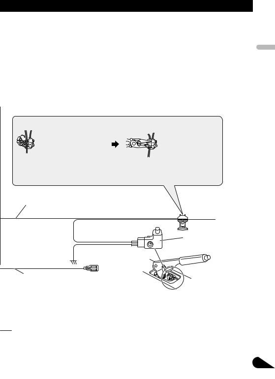
 WARNING
LIGHT GREEN LEAD AT POWER CONNECTOR IS DESIGNED TO DETECT PARKED STATUS AND MUST BE CONNECTED TO THE POWER SUPPLY SIDE OF THE PARKING BRAKE SWITCH. IMPROPER CONNECTION OR USE OF THIS LEAD MAY VIOLATE APPLICABLE LAW AND MAY RESULT IN SERIOUS INJURY OR DAMAGE.
Connection method
1. Clamp the lead. |
2. Clamp firmly with |
|
needle-nosed |
|
pliers. |
Note:
•The position of the parking brake switch depends on the vehicle model. For details, consult the vehicle Owner’s Manual or dealer.
Light green
Used to detect the ON/OFF status of the parking brake.
This lead must be connected to the power supply side of the parking brake switch.
Power supply side
Ground side
Blue/white
When the source is switched ON, a control signal is output.
To system control terminal of the power amp (max. 300 mA 12 V DC).
Parking brake switch
With a 2 speaker system, do not connect anything
to the speaker leads that are not connected to speakers.
Fig. 4
English
Español
Italiano Français Deutsch
Nederlands
6
Connecting the Units
When connecting to separately sold power amp
Center output (CENTER OUTPUT)
23 cm (9 in.)
This product |
Noise filter |
(small) |
Lock tie |
Subwoofer output (SUBWOOFER OUTPUT)
23 cm (9 in.)
|
Rear output |
15 cm |
(REAR OUTPUT) |
|
|
(5-7/8 in.) |
|
|
Front output |
|
(FRONT OUTPUT) |
15 cm
(5-7/8 in.)
Blue/white
When the source is switched ON, a control signal is output.
To system control terminal of the power amp (max. 300 mA 12 V DC).
See the section “Attaching the noise filters”.
7
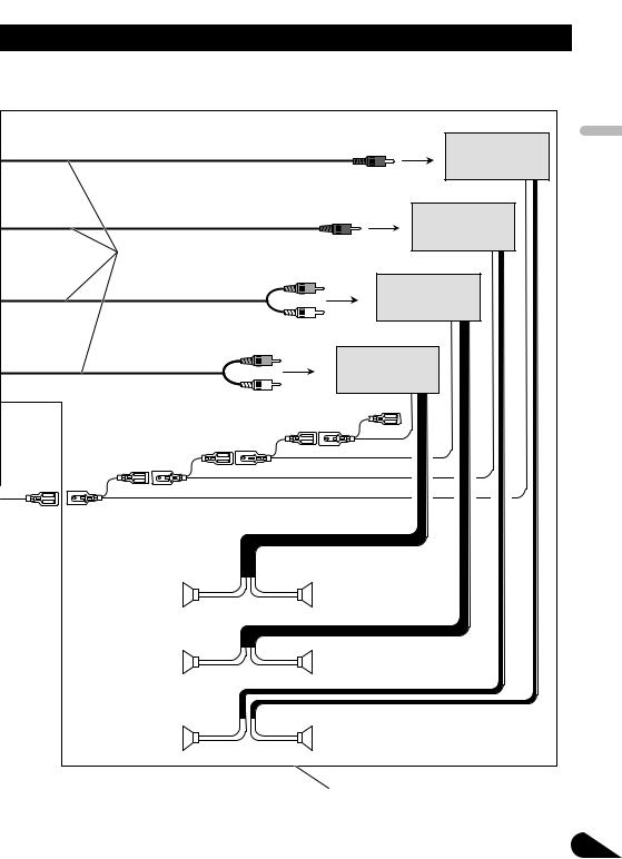
Power amp (sold separately)
Power amp (sold separately)
RCA cables (sold separately)
Power amp (sold separately)
Power amp (sold separately)
System remote control |
|
Left |
Right |
Front speaker |
Front speaker |
Rear speaker |
Rear speaker |
Subwoofer |
Center speaker |
|
Perform these connections when using |
|
the optional amplifier. |
Fig. 5
English
Español
Italiano Français Deutsch
Nederlands
8

Connecting the Units
When connecting with a rear view camera
When using this product with a rear view camera, automatic switching to video from a rear view camera when the gear shift is moved to REVERSE (R) position is possible.
WARNING:
•USE INPUT ONLY FOR REVERSE OR MIRROR IMAGE REAR VIEW CAMERA. OTHER USE MAY RESULT IN INJURY OR DAMAGE.
CAUTION:
•The screen image may appear reversed.
•The rear view camera function is to use this product as an aid to keep an eye on trailers, or backing into a tight parking spot. Do not use this function for entertainment purposes.
•The object in rear view may appear closer or more distant than in reality.
9
This product
 CAUTION
Pioneer recommends the use of a camera which outputs mirror reversed images, otherwise screen image may appear reversed.
15 cm |
8 m |
(5-7/8 in.) |
(26 ft. 3 in.) |
Hide-away unit
RCA cable (sold separately)
Rear view camera
To video output
Extension lead (supplied)
Violet/white |
Fuse resistor |
Of the two lead wires connected to the back |
|
lamp, connect the one in which the voltage |
|
changes when the gear shift is in the REVERSE |
|
(R) position. |
|
Connection method |
|
1. Clamp the lead. |
2. Clamp firmly with |
|
needle-nosed |
|
pliers. |
Note:
• It is necessary to set to BACK UP CAMERA in SETUP when connecting the rear view camera.
Fig. 6
English
Español
Italiano Français Deutsch
Nederlands
10
 Loading...