


AMPLIFIER MANUAL
MANUAL DEL AMPLIFICADOR
MANUEL DEL’AMPLIFICATEUR
|
|
|
Models: Z500.1, Z250.2, Z500.4 |
Features: |
Características: |
Caractéristiques: |
|
• Compact Size for Easy Installation |
• Tamaño compacto de fácil instalación |
• Petit format pour faciliter l’installation |
|
• High and Low Pass Crossovers |
• High and Low Pass Crossovers |
• Filtres croisés passe-haut et passe-bas |
|
• |
Audiophile BiPolar Output Transistors |
• Transistores de salida BiPolar Audiophile |
• Audiophile Transistors de Bipolaire |
• High Level Inputs for easy OEM Integration |
• Entradas de alto nivel para fácil integración OEM |
• Le Niveau Supérieur entre pour l’intégration |
|
• Robust Unregulated Power Supply |
• Robusta y no regulada Fuente de Poder |
de fabricant d’origine facile |
|
• Surface Mount Component Technology |
• Tecnología “Surface Mount Component” |
• Alimentation électrique robuste non réglementée |
|
• Direct Insert Power and Speaker Terminals |
• Conexiones directas de terminales de poder y de |
• Technologie de composant monté en surface |
|
• Audio Precision Quality Control Verification |
parlantes |
• Terminaux d’alimentation et de haut-parleurs à |
|
• |
High Temperature Plexiglass cover |
• Control de verificación de calidad de precisión de audio |
insertion directe |
• Remote subwoofer level control included |
• Cubierta de Plexiglás resistente a altas temperaturas |
• Vérification du contrôle de la qualité de la précision audio |
|
|
(Z500.1 only) |
• Control de nivel de Subwoofer remoto incluido (solo el |
• Couvercle de plexiglas résistant aux températures élevées |
• RMD - Remote Monitoring Display Port |
Z500.1) |
• Niveau de contrôle de passe-bas inclus (Z500.1) |
|
|
|
• Puerto de display para monitoreo remoto (RMD) |
• RMD - Entrée De L’affichage de Tension a Distance |
© 2012 Phoenix Gold • www.phoenixgold.com
Amplifier Owner’s Manual
OWNER INFORMATION
Owner’s Name:
Serial Number:
Purchase Location:
Purchase Date:
Installer:
© 2012 Phoenix Gold • www.phoenixgold.com

Amplifier Owner’s Manual
Z500.1 SPECIFICATIONS
Frequency Response: Signal to Noise Ratio: Low Pass Crossover:
Subsonic Filter:
Low Pass Crossover Range: Subsonic Crossover Range: Bass Boost @ 45Hz:
Low Level Input Range: Lowest Recommend Load: Typical Efficiency: Damping Factor:
± 1dB from 20Hz to 300Hz >100dB
12dB per Octave 12dB per Octave 30Hz to 300Hz 10Hz to 55Hz
0 to +18dB
200 millivolts to 8 volts
2 ohms
50%
Greater than 200
Z250.2 SPECIFICATIONS
Frequency Response: |
± 1dB from 20Hz to 20kHz |
Signal to Noise Ratio: |
>100dB |
High and Low Pass Crossovers: |
12dB per Octave |
Crossover Range: |
40Hz to 400Hz |
Bass Boost @ 45Hz: |
0 to +18dB |
Low Level Input Range: |
200 millivolts to 8 volts |
Lowest Recommend Load: |
4 ohm Bridged or 2 ohm Stereo |
Typical Efficiency: |
50% |
Damping Factor |
Greater than 200 |
Z500.4 SPECIFICATIONS
Frequency Response: |
± 1dB from 20Hz to 20kHz |
Signal to Noise Ratio: |
>100dB |
High and Low Pass Crossovers: |
12dB per Octave |
Crossover Range: |
40Hz to 400Hz |
Low Level Input Range: |
200 millivolts to 8 volts |
Lowest Recommend Load: |
4 ohm Bridged or 2 ohm Stereo |
Typical Efficiency: |
50% |
Damping Factor |
Greater than 200 |
SPECIFICATIONS
Power Output: |
300 x 1 @ 4 ohms |
|
500 x 1 @ 2 ohms |
Power/Ground Wire Size: |
8 Gauge |
Dimensions (Includes Mounting Feet): |
12.5” L x 8.34”W x 2.1” H |
|
318mm L x 213mm W x 53mm H |
Power Output |
75 x 2 @ 4 ohms Stereo |
|
|
125 x 2 |
@ 2 ohms Stereo |
|
250 x 1 |
@ 4 ohm sBridged |
Power/Ground Wire Size: |
8 Gauge |
|
Dimensions (Includes Mounting Feet): |
8.2” L x 8.34”W x 2.1” H |
|
|
208mm L x 213mm W x 53mm H |
|
Power Output |
75 x 4 @ 4 ohms Stereo |
|
|
125 x 4 |
@ 2 ohms Stereo |
|
250 x 2 |
@ 4 ohms Bridged |
Power/Ground Wire Size: |
8 Gauge |
|
Dimensions (Includes Mounting Feet): |
12.5” L x 8.34”W x 2.1” H |
|
|
318mm L x 213mm W x 53mm H |
|
© 2012 Phoenix Gold • www.phoenixgold.com
Amplifier Owner’s Manual
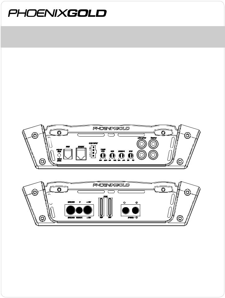
Z500.1
MONOBLOCK POWER AMPLIFIER
INPUT
Connect preamp signal cables from the head unit to these terminals.
CROSSOVER FREQUENCY
Controls the lowpass crossover point for the speaker outputs.
BASS BOOST
Variable bass boost from 0 to +18dB @ 45Hz.
REMOTE BASS LEVEL CONTROL (RBC)
This port is for connecting the remote subwoofer level control. This allows up to 20dB of volume adjustment. This is not a bass boost, it controls the level of the low pass signal.
NOTE: This control is not compatible with the Phoenix Gold LPL44 level control.
SENS
Used to reach maximum amplifier power with a wide variety of headunits.
SUBSONIC CROSSOVER FREQUENCY
Controls the highpass crossover point for the speaker outputs to eliminate extreme low frequencies.
OUTPUT
Provides a full range signal for an additional amplifier. There is no signal loss if using this output.
Z500.1
L L
R R
 Z500.1

 SPEAKE
+12V
This must be connected to the fused positive terminal (+12V) of the car’s battery. The fuse must be located within 18 inches of the battery.
REMOTE
This must be connected to switched +12V, usually a trigger wire coming from the head unit or ignition.
GROUND
This must be connected to the negative terminal of the car’s battery or bolted to a clean, unpainted part of the chassis of the vehicle.
REMOTE MONITORING DISPLAY (RMD)
Connect optional RMD Voltage Diplay to this port.
SPEAKER OUTPUTS
Used to connect the amplifier to speakers. Z500.1 minimum impedance is 2 ohms.
NOTE: Visible through the plexiglass cover, a single blue power LED is located in the lower corner of all Z amplifiers.
© 2012 Phoenix Gold • www.phoenixgold.com
Amplifier Owner’s Manual
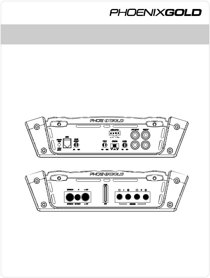
Z250.2
2 CHANNEL POWER AMPLIFIER
INPUT
Connect preamp signal cables from headunit to these input.
CROSSOVER FREQUENCY
Controls the crossover point for the speaker outputs.
OUTPUT
Provides a full range signal for an additional amplifier. There is no signal loss if using this output.
BASS BOOST
Variable bass boost from 0 to +18dB @ 45Hz.
SENS
Used to reach maximum amplifier power with a wide variety of headunits.
CONFIG
FLAT: Crossovers are turned off
HPF: High pass crossover is on
LPF: Low pass crossover is on
Z250.2 |
|
L |
L |
R R
Z250.2
+12V
This must be connected to the fused positive terminal (+12V) of the car’s battery. The fuse must be located within 18 inches of the battery.
REMOTE
This must be connected to switched +12V, usually a trigger wire coming from the head unit or ignition.
GROUND
This must be connected to the negative terminal of the car’s battery or bolted to a clean, unpainted part of the chassis of the vehicle.
REMOTE MONITORING DISPLAY (RMD)
Connect optional RMD Voltage Diplay to this port.
SPEAKER OUTPUTS
Used to connect the amplifier to speakers. Z250.2 minimum impedance is 4 ohms bridged or 2 ohms stereo. Use Right + and Left - to bridge the channels.
NOTE: Visible through the plexiglass cover, a single blue power LED is located in the lower corner of all Z amplifiers.
© 2012 Phoenix Gold • www.phoenixgold.com

Amplifier Owner’s Manual
Z500.4
4 CHANNEL POWER AMPLIFIER
FRONT AND REAR INPUTS
Connect preamp signal cables from headunit to these inputs. The front AND rear inputs must be used, if only the front input is used then the rear speaker outputs will have no output signal.
CROSSOVER FREQUENCY
Controls the crossover point for the speaker outputs.
SENS
Used to reach maximum amplifier power with a wide variety of headunits.
CONFIG
FLAT: Crossovers are turned off
HPF: High pass crossover is on
LPF: Low pass crossover is on
Z500.4 |
|
L |
L |
R |
R |
 Z500.4
+12V
This must be connected to the fused positive terminal (+12V) of the car’s battery. The fuse must be located within 18 inches of the battery.
REMOTE
This must be connected to switched +12V, usually a trigger wire coming from the head unit or ignition.
GROUND
This must be connected to the negative terminal of the car’s battery or bolted to a clean, unpainted part of the chassis of the vehicle.
REMOTE MONITORING DISPLAY (RMD)
Connect optional RMD Voltage Diplay to this port.
SPEAKER OUTPUTS
Used to connect the amplifier to speakers. Z500.4 minimum impedance is 4 ohms bridged or 2 ohms stereo. Use Right + and Left - to bridge the channels.
NOTE: Visible through the plexiglass cover, a single blue power LED is located in the lower corner of all SD amplifiers.
© 2012 Phoenix Gold • www.phoenixgold.com
 Loading...