


IntelliFlo®
Variable Speed Pump (Compatible with IntelliTouch™ and IntelliComm)
Installation
and
User's Guide
Listed
IMPORTANT SAFETY INSTRUCTIONS READ AND FOLLOW ALL INSTRUCTIONS SAVE THESE INSTRUCTIONS
Customer Support
Sanford, North Carolina (8 A.M. to 5 P.M.)
Phone: (800) 831-7133
Moorpark, California (8 A.M. to 5 P.M.)
Phone: (800) 831-7133 (Ext. 6312)
Fax: (800) 284-4151
Web sites: visit www.pentairpool.com and www.staritepool.com
© 2005 Pentair Water Pool and Spa, Inc. All rights reserved
This document is subject to change without notice
1620 Hawkins Ave., Sanford, NC 27330 • (919) 566-8000
10951 West Los Angeles Ave., Moorpark, CA 93021 • (805) 553-5000
Trademarks and disclaimers: IntelliFlo, IntelliTouch and the Pentair Water Pool and Spa logo are trademarks of Pentair Water Pool and Spa, Inc. Other trademarks and trade names may be used in this document to refer to either the entities claiming the marks and names or their products. Pentair Water Pool and Spa, Inc. disclaims proprietary interest in marks and names of others.
P/N 350075 - Rev B - 12/29/2005

i
Contents |
|
Important Safety Precautions ........................................................................................... |
ii |
Section 1: Introduction ...................................................................................................... |
1 |
IntelliFlo Overview ................................................................................................................ |
1 |
IntelliFlo Features ..................................................................................................... |
2 |
IntelliFlo Motor Assembly ......................................................................................... |
2 |
IntelliFlo Motor Features ........................................................................................... |
3 |
IntelliFlo Drive Assembly and Control Panel ............................................................. |
4 |
Operator Control Panel Features .............................................................................. |
4 |
Section 2: Operator Control Panel ................................................................................... |
5 |
IntelliFlo Operator Control Panel ........................................................................................... |
5 |
Controls and LEDs ................................................................................................... |
5 |
Navigating the Menu Structure ............................................................................................. |
7 |
Section 3: Operating IntelliFlo .......................................................................................... |
9 |
How To Meter a System ....................................................................................................... |
9 |
Manual Mode ........................................................................................................................ |
9 |
IntelliFlo Control Panel Menu ............................................................................................... |
11 |
Menu Structure .................................................................................................................... |
12 |
Pool Data Mode ....................................................................................................... |
13 |
Priming Mode ........................................................................................................... |
14 |
Priming Menu ........................................................................................................ |
14 |
Filter Mode ............................................................................................................... |
16 |
Filter Menu ............................................................................................................ |
16 |
Programming Cycles Per Day .............................................................................. |
17 |
Filter Cycle Settings ............................................................................................. |
18 |
Clean Filter Pressure Example ............................................................................. |
19 |
Alert Status ........................................................................................................... |
19 |
Using Filter mode with Features mode ................................................................. |
20 |
Filter Mode and Flow Control ................................................................................ |
21 |
Flow Control and Filter Mode ................................................................................ |
21 |
Time and Contrast Menu ......................................................................................... |
22 |
Setting System Time ............................................................................................. |
22 |
Setting the LCD Backlight Contrast ...................................................................... |
22 |
Features Mode ........................................................................................................ |
23 |
Features 1 & 2 ...................................................................................................... |
23 |
Features 3 -9 ........................................................................................................ |
23 |
M. O. Flo ................................................................................................................ |
23 |
Feature Settings ................................................................................................... |
24 |
How to use the Feature 1 or 2 (Flow and Duration) mode .................................... |
25 |
Features 1 – 2 (Flow and Duration) ...................................................................... |
26 |
To run Feature 1 or 2 (Flow and Duration) ............................................................ |
26 |
Features 3 – 9 (Flow, Start/Stop Time) ................................................................. |
26 |
Enabling Features 3 – 9 ........................................................................................ |
26 |
Mo Flo (Modulation Output flow) ........................................................................... |
28 |
IntelliFlo Installation and User’s Guide
ii
Contents (Continued) |
|
External Control with IntelliComm Communication Center ....................................... |
29 |
External Control ..................................................................................................... |
29 |
Setting up External Control using IntelliComm.......................................................... |
30 |
Controlling IntelliFlo with IntelliTouch......................................................................... |
31 |
Connecting IntelliFlo to IntelliTouch ........................................................................... |
33 |
Backwash Mode ....................................................................................................... |
33 |
Backwash menu .................................................................................................... |
33 |
Running Backwash mode...................................................................................... |
34 |
Backwash menu screens ...................................................................................... |
34 |
Vacuum Mode ........................................................................................................... |
35 |
Vacuum menu ........................................................................................................ |
35 |
Section 4: Maintenance ...................................................................................................... |
37 |
Pump Strainer Basket Service ............................................................................................. |
37 |
Motor Service ....................................................................................................................... |
38 |
Winterizing ............................................................................................................................ |
39 |
Manual Priming and Initial Start-up After Service ................................................................. |
39 |
Section 5: Installation and Removal ................................................................................. |
41 |
Installing the IntelliFlo ........................................................................................................... |
41 |
Location .................................................................................................................... |
41 |
Piping ........................................................................................................................ |
41 |
Check Valves ........................................................................................................... |
41 |
Wiring the IntelliFlo ............................................................................................................... |
42 |
Pump Disassembly .............................................................................................................. |
43 |
Pump Reassembly/Seal Replacement ..................................................................... |
44 |
Shaft Seal Replacement ........................................................................................... |
44 |
Drive Assembly Removal and Installation ............................................................................ |
45 |
Illustrated Parts List .............................................................................................................. |
46 |
Replacement Parts ............................................................................................................... |
46 |
IntelliFlo Pump Dimensions .................................................................................................. |
47 |
IntelliFlo Flow and Power vs Flow Pump Curve ................................................................... |
47 |
IntelliFlo Electrical Specifications ......................................................................................... |
47 |
Section 5: Troubleshooting ............................................................................................... |
49 |
Alerts and Warnings ............................................................................................................. |
49 |
Suction Blockage ................................................................................................................. |
49 |
General IntelliFlo Troubleshooting Problems......................................................................... |
50 |
General Warnings ................................................................................................................. |
52 |
Electrical Cost Overview...................................................................................................... |
52 |
How to make your pool more energy efficient ...................................................................... |
53 |
Using your IntelliFlo pump .................................................................................................... |
53 |
Automatic pool sweeps (booster pump style) ...................................................................... |
53 |
Filter during off-peak times ................................................................................................... |
53 |
Setting filtering time .............................................................................................................. |
53 |
Preventive maintenance ....................................................................................................... |
54 |
Energy Efficient IntelliFlo pump ............................................................................................ |
54 |
IntelliFlo Installation and User’s Guide
iii
IMPORTANT SAFETY PRECAUTIONS


 Important Notice:
Attention Installer: This manual contains important information about the installation, operation and safe use of this product.This information should be given to the owner and/or operator of this equipment.
 WARNING — Before installing this product, read and follow all warning notices and instructions which are included. Failure to follow safety warnings and instructions can result in severe injury, death, or property damage. Call (800) 831-7133 for additional free copies of these instructions.
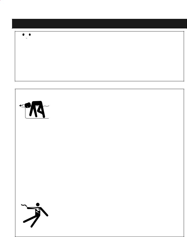
 WARNING — Entrapment Avoidance Notice:
The suction outlet connected to a swimming pool or spa pump can pull a high vacuum if it is blocked. Therefore, if only one suction outlet smaller than 18" x 23" is used, anyone blocking the suction outlet with their body can be trapped and held against the suction outlet. Disembowelment or drowning can result. Therefore, if small suction outlets are used with this pump, to prevent this entrapment and possible death, install at least two suction outlets in the body of water. Separate these suction outlets as described in the International Residential Code (IRC), the International Business Code (IBC), the Consumer Products Safety Council (CPSC) Guidelines for Entrapment Hazards: Making Pools and Spas Safer or ANSI/IAF-7 Standard for Suction Entrapment Avoidance in Swimming Pools, Wading Pools, Spas, Hot Tubs and Catch Basins. If suction outlets are not used, additional entrapment avoidance measures as described in the CPSC Guidelines or ANSI/IAF-7 should be employed.
The covers used on suction outlets should be approved and listed as conforming to the currently published edition of ANSI/ASME A112.19.8 Standard covering Suction Fittings for Use in Swimming Pools, Wading Pools, Spas and Hot Tubs. These covers should be inspected regularly and replaced if cracked, broken or older than the design lifetime indicated on them by the manufacturer. The maximum possible flow rate of this pump should be less than or equal to the maximum approved flow rate indicated on the suction outlet cover by the manufacturer.THE USE OF UNAPPROVED COVERS OR ALLOWING USE OF THE POOL OR SPA WHEN COVERS ARE CRACKED OR BROKEN CAN RESULT IN HAIR ENTANGLEMENT WHICH CAN RESULT IN DEATH.
 WARNING — Risk of electrical shock or electrocution.
This pool pump must be installed by a licensed or certified electrician or a qualified pool serviceman in accordance with the National Electrical Code and all applicable local codes and ordinances. Improper installation will create an electrical hazard which could result in death or serious injury to pool users, installers, or others due to electrical shock, and may also cause damage to property.
Alwaysdisconnectpowertothepoolpumpatthecircuitbreakerbeforeservicingthe pump. Failure to do so could result in death or serious injury to serviceman, pool users or others due to electric shock.
IntelliFlo Installation and User’s Guide

iv
IMPORTANT SAFETY PRECAUTIONS (continued)
 WARNING — Water temperature in excess of 100° Fahrenheit may be hazardous to your health. Prolonged immersion in hot water may induce hyperthermia. Hyperthermia occurs when the internal temperature of the body reaches a level several degrees above normal body temperature of 98.6° F. (37° C.). The symptoms of hyperthermia include: drowsiness, lethargy, dizziness, fainting, and an increase in the internal temperature of the body.
The effects of hyperthermia include: 1) Unawareness of impending danger. 2) Failure to perceive heat. 3) Failure to recognize the need to leave the spa. 4) Physical inability to exit the spa. 5) Fetal damage in pregnant women. 6) Unconsciousness resulting in danger of drowning.
 WARNING — The use of alcohol, drugs, or medication can greatly increase the risk of fatal hyperthermia in hot tubs and spas.
 WARNING — To reduce the risk of injury, do not permit children to use this product unless they are closely supervised at all times.
 WARNING — For units intended for use in other than single-family dwellings, a clearly labeled emergency switch shall be provided as part of the installation. The switch shall be readily accessible to the occupants and shall be installed at least 5 feet (1.52 m) away, adjacent to, and within sight of, the unit.
 WARNING — When setting up pool water turnovers or flow rates the operator must consider local codes governing turnover as well as disinfectant feed ratios.
 CAUTION — Install the pump a minimum of five (5) feet from the inside wall of the pool and spa. Canadian installations require a minimum of three (3) meters from pool water.
 CAUTION — A No. 8 AWG or larger conductor must be wired to the motor bonding lug.
 CAUTION — This pump is for use with permanently installed pools and may also be used with hot tubs and spas if so marked. Do not use with storable pools. A permanently installed pool is constructed in or on the ground or in a building such that it cannot be readily disassembled for storage. A storable pool is constructed so that it may be readily disassembled for storage and reassembled to its original integrity and has a maximum dimension of 18 feet (5.49 m) and a maximum wall height of 42 inches (1.07 m).
 CAUTION — For hot tubs and spa pumps, do not install within an outer enclosure or beneath the skirt of a hot tub or spa unless so marked.
 CAUTION — IntelliFlo is capable of generating systems pressures up to 50 psi. Installers must ensure that all system components are rated to withstand at least 50 psi. Over pressurizing the system can result in catastrophic component failure or property damage.
General Installation Information
•All work must be performed by a licensed electrician, and must conform to all national, state, and local codes.
•Install to provide drainage of compartment for electrical components.
IntelliFlo Installation and User’s Guide
1
Section 1
Introduction
IntelliFlo Overview
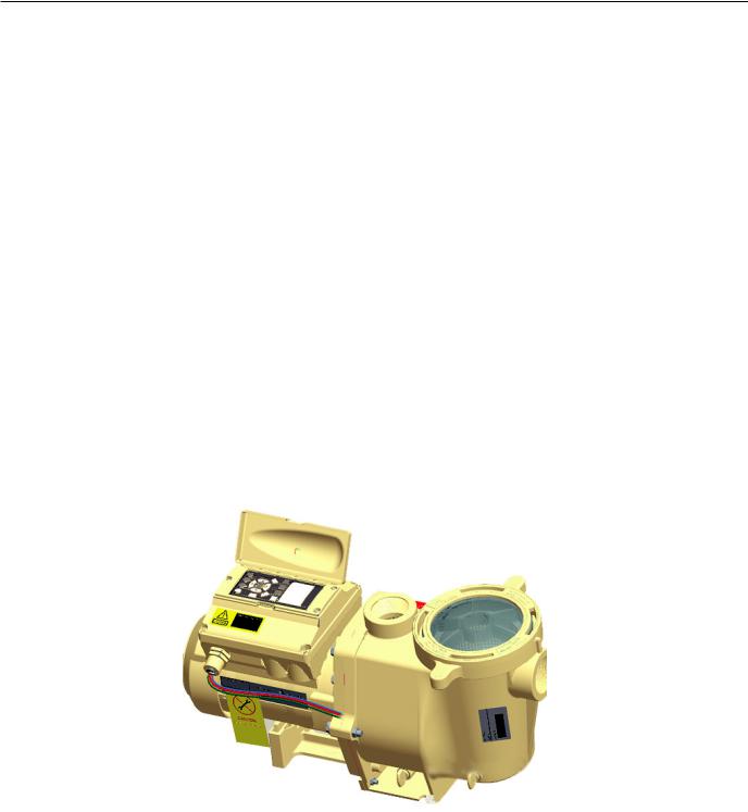
The IntelliFlo variable-speed pump control system offers pool and spa filter automation and advanced features that include energy conservation and programmable scheduled water features for your pool, spa, cleaner, waterfall, and other applications.
The IntelliFlo pump can adapt to any application up to 130 gallons per minute, you simply program IntelliFlo to suit the application. IntelliFlo then dials in the perfect operating conditions.
IntelliFlo can reduce energy cost by as much as 90% based on a pool size up to 15,000 gallons, one turn per day with a 24 hour cycle.
IntelliFlo constantly monitors water flow and electrical current to ensure that the filtration system is operating at peak efficiency. This can result in maximum energy efficiency savings never before possible – up to 90% over conventional pumps. The system protects against loss of prime or impedance of flow, under and over voltage situations, and thermal overload or freezing.
With IntelliFlo there’s no need for pump curves and hydraulic calculations to determine the right pump for the job. Just set the program for your pool size and desired turnover, and IntelliFlo does the rest.
IntelliFlo variable speed pump
IntelliFlo Installation and User’s Guide
2
IntelliFlo Features
•Sizes itself to any pool
•Reduces energy cost by as much as 90%
•Protects against loss of prime or flow blockage
•Prevents thermal overload
•Detects and prevents damage from under and over voltage conditions
•Protects against freezing
•Can communicate with an IntelliTouch or IntelliComm system via a two-wire connection
•Easy to read operator control panel LCD display
•Operator control panel buttons for pump modes
•Built-in strainer pot and volute
•Ultra energy-efficient TEFC Square Flange Motor
•Compatibility with most cleaning systems, filters, and jet action spas
•16-button LCD control panel
•Drive assembly features permanent magnet synchronous motor
•Heavy-duty, durable construction designed for long life
•Internal 24-hour clock for setting controlled on/off times for filtering and up to ten water features
•UL listed
IntelliFlo Motor Assembly
The IntelliFlo three-phase six-pole motor operates at 3450 RPM (at 92% efficiency) and 400 RPM (at 90%). The motor assembly is continually cooled by an external fan. Dual seals on the motor shaft and at the fan assembly seal the entire motor from any moisture entering the motor assembly. For added protection, a slinger located in front of the main shaft seal assists in slinging water away from the shaft opening in the flange.
IntelliFlo Installation and User’s Guide
3
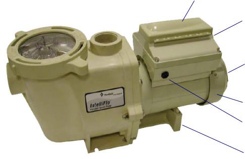
Operator control panel cover
Drive assembly and electronics enclosure
Motor fan cover
Motor assembly
Communication Port for RS-485 (IntelliTouch and IntelliComm)
Motor stand
IntelliFlo Motor Assembly
IntelliFlo Motor Features
•Permanent Magnet Synchronous Motor (PMSM)
•High efficiency (3450 RPM 92% and 400 RPM 90%)
•Superior speed control
•Operates at lower temperatures due to high efficiency
•Same technology as deployed in hybrid electric vehicles
•Designed to withstand outdoor environment
•Totally Enclosed Fan Cooled
•Three-phase motor
•56 Square Flange
•Six-Pole
•Low noise
IntelliFlo Installation and User’s Guide
4
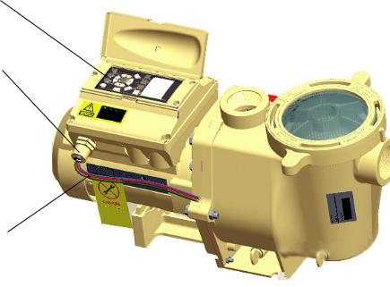
IntelliFlo Drive Assembly and Control Panel
The IntelliFlo drive assembly consists of an operator control panel and the system electronics that drive the 230 VAC single phase (260 VAC~170 VAC) motor. The drive microprocessor controls the motor by changing the frequency of the current it receives together with changing the voltage to control the rotational speed.
Operator Control Panel, buttons and Liquid Crystal Display (LCD)
¾” NPT male nipple
Three Wire Harness
Hot (Red), Hot (Red)
Ground (Green / Yellow)
+/- 20% of 230 Volt
IntelliFlo Drive Assembly
Operator Control Panel Features
•Backwash and Rinse — Informs the user when and how to backwash filter media
•Vacuum — Can be preset using duration and flow parameters to save energy
•Filter — Allows pump to run at peak efficiency, saving users up to 90% in energy cost, based on a pool size up to 15,000 gallons, one turn per day with a 24 hour cycle
•Feature — Ten feature modes can be programmed to control filtration duration, start and stop time, and frequency for cleaners, water features, spas, and waterfalls
•Manual — Allows the user to override all programming and run the pump using RPM or flow (GPM) control parameters
IntelliFlo Installation and User’s Guide
5
Section 2
Operator Control Panel
This section describes the operator control panel controls and LEDs.
IntelliFlo Operator Control Panel
|
|
IntelliFlo® |
|
||
15 |
|
|
|
|
|
|
Filter |
Vacuum |
Back |
Manual |
|
|
mode |
mode |
Wash |
mode |
|
1 |
|
|
|
|
4 |
2 |
Select |
|
Escape |
3 |
|
|
|
|
|||
|
|
|
|
||
5 |
|
|
|
|
6 |
|
On |
Enter |
|
Menu |
7 |
|
|
|
|
|
|
14 |
Warn. |
|
|
|
|
|
Alarm |
|
|
|
8 |
|
|
|
|
|
|
|
|
|
|
|
9 |
|
Feature |
Feature |
Start |
Reset |
|
|
1 |
2 |
Stop |
|
|
|
|
|
|||
10 |
|
|
|
|
13 |
11 |
|
|
|
|
12 |
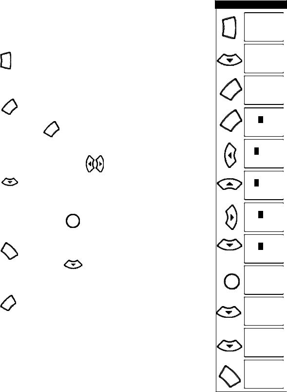
Controls and LEDs
1Filter button/LED: Starts Filter mode. The LED is on when Filter mode is active.
2Vacuum button/LED: Starts Vacuum mode. The LED is on when Vacuum mode is active.
3Backwash button/LED: Starts Backwash mode. The LED is on when Backwash mode is active.
4Manual button/LED: Starts Manual mode. The LED is on when Manual mode is active.
5Select button: Display available menu items or enters edit mode for changing a value on line two of the display.
6Escape button: Go to the next level up in the menu structure or stop editing the current setting.
7Menu button: Access the menu items if the pump is stopped.
8Enter button: Save current menu item setting. Also, press this button to acknowledge alarms and warning alerts.
IntelliFlo Installation and User’s Guide

6
Controls and LEDs (Continued)
9Arrow buttons:
•Up arrow: Move one level up in the menu tree or increase a digit when editing a setting.
•Down arrow: Move one level down in the menu tree or decrease a digit when editing a setting.
•Left arrow: Move cursor left one digit when editing a setting.
•Right arrow: Move cursor right one digit when editing a setting.
10Feature 1 button: Starts Feature 1 mode. The LED is lit when mode is active.
11Feature 2 button: Starts Feature 2 mode. The LED is lit when mode is active.
12Start/Stop button: Start or Stop the pump. When the LED is lit it indicates that the pump is currently running or in a mode to start automatically.
13Reset button: Reset alarm or alert.
LEDs
On: This green LED is on when IntelliFlo is powered on.
14Warning: This LED is on if a warning condition is present.
Alarm: This LED is on if an alarm condition has occurred.
15Control Panel LCD Display
LCD Display Lines:
•Line 1 - Mode and time. To set A.M. and P.M. time, refer to “Time and Contrast Menu” on page 22.
•Line 2 - Data
•Line 3 - Name of data in line 2
•Line 4 - Run status
IntelliFlo Installation and User’s Guide
7
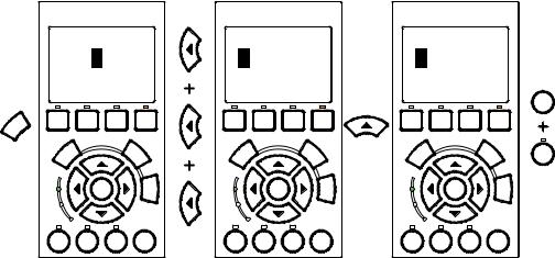
Navigating the Menu Structure
Before navigating the control panel menu structure, first familiarize yourself with the menu buttons. To change a parameter setting, use the Left and Right arrow buttons to select the digit, then the Up and Down arrow buttons to edit the digit. The following example shows how to set the GPM and priming time in the “Priming” menu (see page 14).
To set the “Priming” mode settings:
1. Ensure that the green power LED is on and the pump is stopped. If the pump is running, press the Start/Stop button.
2.Press the Menu Menu button. “Pool Data” is displayed.
3.Press the  Down arrow to select “Priming”.
4.Press the Select Select button to access “Max Priming Flow” setting.
5.Set the GPM: Press the Select Select button to set the gallons per minute (GPM) value.
6. To change the GPM value, press the |
Left and Right arrows to select |
which digit to modify. |
|
Press the  Up and Down arrows to change the selected digit. For setting values, see “Priming menu options” below.
7. When you are done, press the Enter Enter button to save the changes. To cancel any changes.
Press the Escape Escape button to exit edit mode without saving.
8. Set the priming time: Use the  Up and Down arrows to select “Max Priming Time” and “System Priming Time.”
Press the |
Select |
Select to edit the setting. |
9. Repeat steps 5, 6, and 7 to edit the setting.
|
MENU |
12:15 |
|
Menu |
Pool Data |
||
|
|
||
|
MENU |
12:15 |
|
|
Priming |
||
|
Priming |
12:15 |
|
Select |
55. GPM |
||
Max Priming Flow |
|||
|
|||
|
Priming |
12:15 |
|
Select |
0055. GPM |
||
Max Priming Flow |
|||
|
|||
|
Priming |
12:15 |
|
|
0055. GPM |
||
|
Max Priming Flow |
||
|
Priming |
12:15 |
|
|
0065. GPM |
||
|
Max Priming Flow |
||
|
Priming |
12:15 |
|
|
0065. GPM |
||
|
Max Priming Flow |
||
|
Priming |
12:15 |
|
|
0060. GPM |
||
5X |
Max Priming Flow |
||
|
|
||
|
Priming |
12:15 |
|
Enter |
60. GPM |
||
Max Priming Flow |
|||
|
|||
|
Priming |
12:15 |
|
|
15. MIN |
||
|
Max Priming Time |
||
|
Priming |
12:15 |
|
|
0. MIN |
||
|
System Priming Time |
||
|
MENU |
12:15 |
|
Escape |
Priming |
||
|
|
||
IntelliFlo Installation and User’s Guide
8
Blank Page
IntelliFlo Installation and User’s Guide

9
Section 3
Operating IntelliFlo
This section describes how to use the IntelliFlo pump control panel.
Metering the System
The first step to operating and programming IntelliFlo is to know what is being used in the pool system.After the devices are selected you can then set valves for the appropriate features and use the “Manual” mode to measure flow rates for the types or series of devices that require flow. When an appropriate flow rate or rates are found for a device or series of devices, you should note that flow rate for programming later.
Note: If the pool system uses a filter, always monitor pressure at the filter when changing the speed (RPM) or flow (GPM) from IntelliFlo.
Manual Mode
Operating IntelliFlo in manual mode is typically used for service and testing purposes only.
To operate IntelliFlo in manual mode:
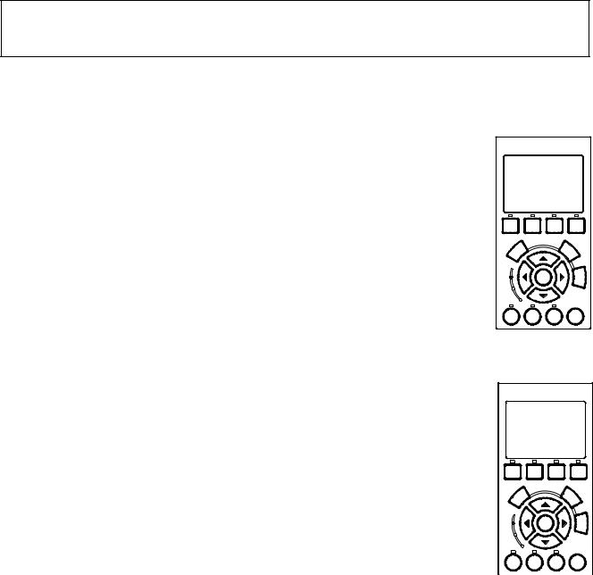
IntelliFlo®
FILTER 1:37
43.GPM
FLOW
RUNNING Schedule
Filter |
Vacuum |
Back |
Manual |
|
mode |
mode |
Wash |
mode |
|
Select |
|
|
Escape |
|
On |
Enter |
|
Menu |
|
Warn. |
|
|
|
|
Alarm |
|
|
|
|
Feature |
Feature |
Start |
Reset |
|
1 |
2 |
Stop |
||
|
1.Ensure that the green power LED is on.
2.Press the Manual button.
3.Use the Up and Down arrow buttons to view the current power, actual speed and flow:
•Power Menu (Watts): Displays current power to the motor shaft in continuous watts
•Actual Speed (RPM): Displays RPM speed when flow and RPM control is used
•Actual Flow (GPM): Displays actual flow when using flow control
•Set Speed (RPM): Set IntelliFlo to run at a continuous speed
•Set Flow (GPM): Set IntelliFlo in flow control to allow the pump to change speed to manage the flow rate based on system changes
IntelliFlo®
MANUAL 12:15
15.W
POWER
STOPPED
Back
Filter Vacuum Manual
Wash
Select |
|
|
Escape |
|
On |
Enter |
|
Menu |
|
Warn. |
|
|
|
|
Alarm |
|
|
|
|
Feature |
Feature |
Start |
Reset |
|
1 |
2 |
Stop |
||
|
IntelliFlo®
MANUAL 12:15
10.RPM
ACTUAL SPEED
STOPPED
Filter |
Vacuum |
Back |
Manual |
|
Wash |
||||
|
|
|
||
Select |
|
|
Escape |
|
On |
Enter |
|
Menu |
|
Warn. |
|
|
|
|
Alarm |
|
|
|
|
Feature |
Feature |
Start |
Reset |
|
1 |
2 |
Stop |
||
|
IntelliFlo®
MANUAL 12:15
13.GPM
FLOW
STOPPED
Back
Filter Vacuum Manual
Wash
Select |
|
|
Escape |
|
On |
Enter |
|
Menu |
|
Warn. |
|
|
|
|
Alarm |
|
|
|
|
Feature |
Feature |
Start |
Reset |
|
1 |
2 |
Stop |
||
|
IntelliFlo®
MANUAL 12:15
10.RPM
Set SPEED
STOPPED
Filter |
Vacuum |
Back |
Manual |
|
Wash |
||||
|
|
|
||
Select |
|
|
Escape |
|
On |
Enter |
|
Menu |
|
Warn. |
|
|
|
|
Alarm |
|
|
|
|
Feature |
Feature |
Start |
Reset |
|
1 |
2 |
Stop |
||
|
IntelliFlo®
MANUAL 12:15
580.GPM
Set FLOW
STOPPED
Filter |
Vacuum |
Back |
Manual |
|
Wash |
||||
|
|
|
||
Select |
|
|
Escape |
|
On |
Enter |
|
Menu |
|
Warn. |
|
|
|
|
Alarm |
|
|
|
|
Feature |
Feature |
Start |
Reset |
|
1 |
2 |
Stop |
||
|
Manual
Note: No sensors except the flow control will work while in “Manual” mode. Suction Blockage will not work in this mode.
IntelliFlo Installation and User’s Guide
10
Manual Mode (Continued)
To change the Set Flow and Set Speed features:
1.Ensure that the green power LED is on.
2.Press the Manual button (LED is on).
3.Set Flow: Use the Up and Down arrow buttons to select Set Flow, then press the Select button to edit the setting.
4.To change the setting, press the Left and Right arrows to select which digit to modify, then use the Up and Down arrows to change the selected digit. The preset flow values can be set to 15 to 130 GPM (default 50 GPM).
5.When you are done, press the Enter button to save the changes. To cancel any changes, press the Escape button to exit edit mode without saving.
6.Set Speed: Use the Up and Down arrows to select Set Speed, then press the Select button to edit the setting. The preset speed can be set to 400 to 3450 RPM maximum (default 1000 RPM).
Select
IntelliFlo®
MANUAL 12:15
0010.RPM
Set SPEED
STOPPED
Filter |
Vacuum |
Back |
Manual |
|
Wash |
||||
|
|
|
||
Select |
|
|
Escape |
|
On |
Enter |
|
Menu |
|
Warn. |
|
|
|
|
Alarm |
|
|
|
|
Feature |
Feature |
Start |
Reset |
|
1 |
2 |
Stop |
||
|
Cursor hi-lights in
Cursor Hi-lights
black
in Black
IntelliFlo®
MANUAL 12:15
0010.RPM
Set SPEED
STOPPED
Filter |
Vacuum |
Back |
Manual |
|
Wash |
||||
|
|
|
||
Select |
|
|
Escape |
|
On |
Enter |
|
Menu |
|
Warn. |
|
|
|
|
Alarm |
|
|
|
|
Feature |
Feature |
Start |
Reset |
|
1 |
2 |
Stop |
||
|
Left/Right arrow
Arrow Keys to buttons to change change Values digit
IntelliFlo®
MANUAL 12:15
1010.RPM
Set SPEED |
|
|
||
STOPPED |
|
|
||
Filter |
Vacuum |
Back |
Manual |
|
Wash |
||||
|
|
|
||
Select |
|
|
Escape |
|
On |
Enter |
|
Menu |
|
Warn. |
|
|
|
|
Alarm |
|
|
|
|
Feature |
Feature |
Start |
Reset |
|
1 |
2 |
Stop |
||
|
||||
Press the Enter
Hit Enter and button to save.
Start/Stop
Press Start/Stop
Enter
Start
Stop
7.To change the setting, press the Left and Right arrows to select which digit to modify, then use the Up and Down arrows to change the selected digit.
8.When you are done, press the Enter button to save the changes. To cancel any changes, press the Escape button to exit edit mode without saving.
IntelliFlo Installation and User’s Guide
11
Manual Mode (Continued)
9.Press the Start/Stop button (LED is on) to run IntelliFlo in “Manual” mode (LED is on). The pump will start and control the flow or speed using the last settings made. After the button is pressed, the display shows “Running.” To stop IntelliFlo, press the Start/Stop button (LED is off). The display will show “Stopped.”
Note: While IntelliFlo is running in Manual mode, you can view the current power consumption and what actual speed is being used.
10.Change Flow and Speed settings while the IntelliFlo is running: The Set Flow and Set Speed settings can be changed on the fly while the pump is running. To change the flow and speed settings, perform steps 3 through 8.
•When “Set Flow” is used IntelliFlo will prime then ramp to the current flow rate
•It takes the IntelliFlo about 60 seconds to two minutes to find a flow rate after it is primed. This is best seen inActual Speed status display
•While changing the Set Flow setting, IntelliFlo will reprime after a value is changed
•While changing the Set Speed setting, IntelliFlo will immediately ramp to the current speed
11.To stop the pump, press the Start/Stop button.
IntelliFlo Control Panel Menu
Use the control panel menu to setup and configure IntelliFlo.
To access the menu features:
•Ensure that the pump is stopped. Press the Menu button. Use the Up or Down arrow button to scroll through the menu items. Use the Select button to select a menu item. Press the Enter button to save a setting. Press the Escape button to move up a level from a selected menu item.
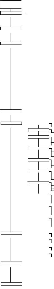
Menu Structure
The IntelliFlo menu structure is shown on the following page.
IntelliFlo Control Panel with IntelliComm or IntelliTouch
•The IntelliFlo control panel remains active when the IntelliFlo is connected to an IntelliComm. For more information see page 29.
•The IntelliFlo control panel is disabled when the Intelliflo is communicating with an IntelliTouch. "DISPLAY NOTACTIVE!" will be displayed. For more information see page 31.
IntelliFlo Installation and User’s Guide
12
Main Structure
MAIN SCREEN Press MENU button to access menu items
POOL DATA
(page 13)
PRIMING
(page 14)
FILTER
(page 16)
TIME / CONTR
(page 22)
FEATURES
(page 23)
|
|
Address |
|
|
|
|
(1 - 16) [Note: 1-8 when connected to IntelliTouch] |
||||||||
|
|
|
|
|
|
|
|
(68˚ - 104˚ F) |
|||||||
|
|
Water |
Temp |
|
|
|
|||||||||
|
|
|
|
|
|
|
|
(1 - 1000 Kgal) |
|||||||
|
|
Pool Volume |
|
|
|
|
|||||||||
|
|
|
|
|
|
|
|
|
(30 - 160 gpm) |
||||||
|
|
Max Priming Flow |
|
|
|
|
|
||||||||
|
|
|
|
|
|
|
|
|
|
|
(1 - 15 min.) |
||||
|
|
Max Priming Time |
|
|
|
|
|
|
|
||||||
|
|
|
|
|
|
|
|
|
|
|
(0 - 5 min.) |
||||
|
|
Sys Priming Time |
|
|
|
|
|
|
|
||||||
|
|
|
|
|
|
|
|
|
|
|
|
(1 - 50 min.) |
|||
|
|
Clean Filter Pressure |
|
|
|
|
|
|
|
|
|||||
|
|
|
|
|
|
|
|
|
|
|
|
(1 - 8 counts) |
|||
|
|
Turnovers per Day |
|
|
|
|
|
|
|
|
|||||
|
|
|
|
|
|
|
|
|
|
|
|
(1 - 4 counts) |
|||
|
|
Cycles per Day |
|
|
|
|
|
|
|
|
|||||
|
|
|
|
|
|
|
|
|
|
|
|
(hr:mm - AM/PM) |
|||
|
|
Start Cycle 1 |
|
|
|
|
|
|
|
||||||
|
|
|
|
|
|
|
|
|
|
|
|
(hr:mm - AM/PM) |
|||
|
|
Stop Cycle 1 |
|
|
|
|
|
|
|
|
|||||
|
|
|
|
|
|
|
|
|
|
|
|
(hr:mm - AM/PM) |
|||
|
|
Start |
Cycle 2 |
|
|
|
|
|
|
|
|
||||
|
|
|
|
|
|
|
|
|
|
|
|
(hr:mm - AM/PM) |
|||
|
|
Stop Cycle 2 |
|
|
|
|
|
|
|
|
|||||
|
|
|
|
|
|
|
|
|
|
|
|
(hr:mm - AM/PM) |
|||
|
|
Start |
Cycle 3 |
|
|
|
|
|
|
|
|
||||
|
|
|
|
|
|
|
|
|
|
|
|
|
(hr:mm - AM/PM) |
||
|
|
Stop Cycle 3 |
|
|
|
|
|
|
|
|
|
|
|
|
|
|
|
|
|
|
|
|
|
|
|
|
|
|
(hr:mm - AM/PM) |
||
|
|
Start |
Cycle 4 |
|
|
|
|
|
|
|
|
|
|||
|
|
|
|
|
|
|
|
|
|
|
|||||
|
|
|
|
|
|
|
|
|
|
|
|
|
(hr:mm - AM/PM) |
||
|
|
Stop Cycle 4 |
|
|
|
|
|
|
|
|
|
||||
|
|
|
|
|
|
|
|
|
|
|
|
|
|
|
(hr:min - AM/PM) |
|
|
Clock |
|
|
|
|
|
|
|
|
|
|
|
||
|
|
|
|
|
|
|
|
|
|
|
|
|
(0 - 9) |
||
|
|
Contrast Level |
|
|
|
|
|
|
|
|
|
||||
|
|
|
|
|
|
|
|
|
|
|
|
|
|
|
Set Flow (15 - 130 gpm) |
|
|
Features 1 |
|||||||||||||
|
|
|
|
|
|
|
|
|
|
|
|
||||
|
|
|
|
|
|
|
|
|
|
|
|
|
|
|
Set Duration (0:01 - 10:00) |
|
|
|
|
|
|
|
|
|
|
|
|
|
|
||
Features 2
Features 3
Features 4
Features 5
Features 6
Features 7
 Set Flow (15 - 130 gpm) Set Duration (0:01 - 10:00)

 Disable/Enable
Set Flow (15 - 130 gpm)
Set Start Time (hr:mm AM/PM)
Set Stop Time (hr:mm AM/PM)
 Disable/Enable
Set Flow (15 - 130 gpm)
Set Start Time (hr:mm AM/PM)
Set Stop Time (hr:mm AM/PM)
 Disable/Enable
Set Flow (15 - 130 gpm)
Set Start Time (hr:mm AM/PM)
Set Stop Time (hr:mm AM/PM)
 Disable/Enable
Set Flow (15 - 130 gpm)
Set Start Time (hr:mm AM/PM)
Set Stop Time (hr:mm AM/PM)
 Disable/Enable
Set Flow (15 - 130 gpm)
Set Start Time (hr:mm AM/PM)
Set Stop Time (hr:mm AM/PM)
Features 8 |
|
|
Disable/Enable |
|
|
|
|||
|
|
|
|
Set Flow (15 - 130 gpm) |
|
|
|
|
|
|
|
|
|
Set Start Time (hr:mm AM/PM) |
|
|
|
|
|
|
|
|
|
Set Stop Time (hr:mm AM/PM) |
|
|
|
|
|
|
|
|
|
Disable/Enable |
Features 9 |
|
|
||
|
|
|
|
Set Flow (15 - 130 gpm) |
|
|
|
|
|
|
|
|
|
Set Start Time (hr:mm AM/PM) |
|
|
|
|
|
|
|
|
|
Set Stop Time (hr:mm AM/PM) |
|
|
|
|
|
|
|
|
|
|
M.O Flow |
|
|
Disable/Enable |
|
|
|
|
|
Set Flow (15 - 130 gpm) |
|
|
|
|
|
|
|
|
|
Set Run Time (0:01 - 00:59) |
|
|
|
|
|
|
|
|
|
Set Interval Time (0:02 - 4:15) |
|
|
|
|
|
EXT. CONTROL
(page 29)
BACKWASH
(page 33)
VACUUM
(page 35)
|
Program 1 |
|
|
Disable/Enable |
|
|
|
|
|
|
Set Flow (15 130 gpm) / Time Delay Stop (hr:mn) (0:00 - 0:10) |
|
|
|
|
|
Disable/Enable (15 - 130 gpm) |
|
Program 2 |
|
|
||
|
|
|
|
|
Set Flow (15 130 gpm) / Time Delay Stop (hr:mn) (0:00 - 0:10) |
|
|
|
|
|
Disable/Enable |
|
Program 3 |
|
|
||
|
|
|
|
|
Set Flow (15 130 gpm) / Time Delay Stop (hr:mn) (0:00 - 0:10) |
|
|
|
|
|
|
|
|
|
|
|
Disable/Enable |
|
Program 4 |
|
|
||
|
|
|
|
|
Set Flow (15 130 gpm) / Time Delay Stop (hr:mn) (0:00 - 0:10) |
|
|
|
|
|
|
|
|
|
|
|
(15 - 130 gpm) |
|
Backwash Flow |
|
|
||
|
|
|
(0:01 - 1:00) |
||
|
Backwash Duration |
||||
|
|
|
(0:01 - 1:00) |
||
|
Rinse Time |
||||
|
|
|
|
|
(15 - 130 gpm) |
|
Vacuum Flow |
|
|
||
|
|
|
|
(0:01 - 10:00) |
|
|
Vacuum Duration |
|
|||
IntelliFlo Installation and User’s Guide
13
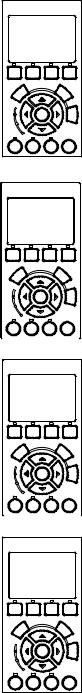
Pool Data Mode
Use the Pool Data menu to configure IntelliFlo for the pool and spa system. From this menu you can set an address for the IntelliFlo pump when connected to an IntelliTouch system, set the volume of pool water, in 1000’s of gallons (kgal) and estimated pool water temperature.
To access the Pool Data menu:
1.Ensure that the green power LED is on and the pump is stopped.
2.Press the Menu button.
3.Press the Up and Down arrow buttons to scroll through the menu items. Press the Select button to access the “Pool Data” menu.
4.To enter the pump volume (pool size): Press the Select button to access “Pool Volume” setting. To enter the pool volume setting, see step 7.
The “Pool Volume” value is expressed as 1000’s of gallons (Kgal). Enter from 1 to 1000 Kgal for the pool volume. The volume number can be a close estimate, although the more accurate the better the turns will be done when employing filter mode. Filter mode uses this value in coordination with the parameters from Filter mode to sustain turn rates, flows, and times.
5.To set the water temperature: Use the Up and Down arrows to select “Water Temperature”. To set the water temperature, see step 7.
Enter the current water temperature from 68° F - 104° F (Default 75° F.) The “Water Temp” is only for the accuracy of the flow sensor. Temperature accuracy is not critical, just enter an approximate temperature. When the IntelliFlo is connected to an IntelliTouch system, water and air temperature information is provided by the system sensors. The flow reading on the IntelliFlo is –0 / +2 GPM. The closer the temperature to the actual temperature, the more accurate the flow reading on the IntelliFlo control panel LCD will be while it’s running.
6.To enter the pump address: Press the Select button to access the “Pump Address” setting. To enter the IntelliFlo pump address, see step 7.
This setting is only used if IntelliFlo is connected to the IntelliTouch system. The “Pump Address” identifies the pump number (1-16) that is displayed on the IntelliTouch control panel for programming. For example, if there are multiple IntelliFlo pumps, pump address 1 can be name as “Spa Pump,” in the IntelliTouch control panel. The IntelliTouch system can address and control up to eight different pumps using the RS-485 COM port connection. Note: IntelliFlo pumps cannot be connected in series with other pumps. Check valves must be used when an IntelliFlo is used in parallel with other pumps.
7.Press the Select button to change the current setting.
8.To enter a new setting, press the Left and Right arrows to select which digit to modify, then use the Up and Down arrows to change the selected digit.
9.When you are done, press the Enter button to save the changes. To cancel any changes, press the Escape button to exit edit mode without saving.
IntelliFlo®
MENU 12:15
Pool Data
Back
Filter Vacuum Manual
Wash
Select |
|
|
Escape |
|
On |
Enter |
|
Menu |
|
Warn. |
|
|
|
|
Alarm |
|
|
|
|
Feature |
Feature |
Start |
Reset |
|
1 |
2 |
Stop |
||
|
IntelliFlo®
Pool Data |
|
12:01 |
||
|
1 |
|
|
|
Pump Address |
|
|||
Filter |
Vacuum |
Back |
Manual |
|
Wash |
||||
|
|
|
||
S |
|
|
Escape |
|
ct |
|
|
|
|
ele |
|
|
|
|
On |
Enter |
|
Menu |
|
Warn. |
|
|
|
|
Alarm |
|
|
|
|
Feature |
Feature |
Start |
Reset |
|
1 |
2 |
Stop |
||
|
IntelliFlo® |
|||
Pool Data |
|
12:15 |
||
|
31.kGAL |
|||
Pool Volume |
|
|||
Filter |
Vacuum |
Back |
Manual |
|
Wash |
||||
|
|
|
||
S |
|
|
Escape |
|
ct |
|
|
||
ele |
|
|
|
|
On |
Enter |
Menu |
||
Warn. |
|
|
|
|
Alarm |
|
|
|
|
Feature |
Feature |
Start |
Reset |
|
1 |
2 |
Stop |
||
|
IntelliFlo® |
|||
Pool Data |
|
12:15 |
||
75.F
Water Temperature
Filter |
Vacuum |
Back |
Manual |
|
Wash |
||||
|
|
|
S |
|
|
Escape |
|
ct |
|
|
|
|
ele |
|
|
|
|
On |
Enter |
|
Menu |
|
Warn. |
|
|
|
|
Alarm |
|
|
|
|
Feature |
Feature |
Start |
Reset |
|
1 |
2 |
Stop |
||
|
IntelliFlo Installation and User’s Guide
14
Priming Mode
To “prime” a pump means filling the pump and suction pipe with water. This process evacuates the air from all the suction lines and the pump. It may take several minutes to prime depending on the depth of water, pipe size and length. It is easier to prime a pump if you allow all the air to escape from the pump and pipes. The water cannot enter unless the air can escape. Pumps do not hold prime, the pool piping system has that task.
Priming is a function used every time the motor is started with a flow as reference. The “Priming Flow” function ensures the proper operation of the pump. The “System Priming Time” function ensures proper operation of the whole pool system. When the pump is priming, the control panel LCD displays “Priming” and then for a moment displays “Primed” when priming is complete.
 CAUTION: To avoid permanent damage to the IntelliFlo pump, before starting the system, fill the IntelliFlo housing strainer with water so that the pump will prime correctly. If there is no water in the stainer the pump will not prime.
Priming Menu
To enter maximum priming flow (GPM):
1.Ensure that the green power LED is on and the pump is stopped.
2.Press the Menu button. “Pool Data” is displayed.
3.Press the Up or Down arrows to select the “Priming” menu.
4.To set the Max Priming Flow (GPM): Press the Select button to access the “Max Priming Flow” setting. To enter the maximum flow range (GPM) during the priming cycle, see step 7.
The “Max Priming Flow” value is entered as gallons per minute (GPM), from 30 to 160 GPM. The default is 55 GPM. The “Max Priming Flow” is a critical parameter for the pool and equipment. Every time the pump starts this parameter will negotiate the maximum flow of the pump. If the flow is too high, equipment damage can occur. If the flow is to low the pump will not prime. This “flow” is system dependent and may require iteration. The pump will never flow more than this parameter is set to, however, it is common for the pump to ramp up and down quickly while priming. Always try to keep this flow as low as possible for cost savings and safety.
IntelliFlo®
MENU 12:37
Priming
Back
Filter Vacuum Manual
Wash
Select |
|
|
Escape |
|
On |
Enter |
|
Menu |
|
Warn. |
|
|
|
|
Alarm |
|
|
|
|
Feature |
Feature |
Start |
Reset |
|
1 |
2 |
Stop |
||
|
IntelliFlo®
5. |
To set the Max Priming Time: Press the Select button to access the “Max |
Priming |
|
12:44 |
|
|
55.GPM |
||||
|
Priming Time” setting. To enter the maximum time for priming before “PRIMING |
|
|||
|
Max Priming Flow |
||||
|
ERROR”, see step 7 on the following page. |
||||
|
|
|
|
|
|
|
The “Max Priming Time” value is entered in minutes, from 1 to 15 minutes. The |
Filter |
Vacuum |
Back |
Manual |
|
Wash |
||||
|
|
|
|
||
|
default is 15 minutes. Use this parameter to set the time that you want IntelliTouch |
elect |
|
Escape |
|
|
to try and prime before it reports an error. Remember that the IntelliFlo will attain |
|
|||
|
S |
|
|
||
|
|
|
|
|
|
|
prime every time it starts and goes through this cycle. The IntelliFlo mechanical |
On |
Enter |
|
Menu |
|
|
|
|
||
|
seal can withstand about 15 minutes before severe damage occurs. You can set |
Warn. |
|
|
|
|
Alarm |
|
|
|
|
|
this range between 1 minute to 15 minutes. The lower the time the quicker you will |
|
|
|
|
|
Feature |
Feature |
Start |
Reset |
|
|
get a priming error if the system is difficult to prime.A well plumbed pool without |
1 |
2 |
Stop |
|
|
|
||||
|
|
|
|
|
|
|
having the strainer removed should prime in less than 30 seconds. If the strainer |
|
|
|
|
|
has been removed for cleaning and a substantial amount of air is in the system it should prime in |
|
|||
|
about 60 to 90 seconds on the average, however, all systems will be different. |
|
|
|
|
IntelliFlo Installation and User’s Guide
 Loading...