


EasyTouch 8 and 4
IMPORTANT SAFETY INSTRUCTIONS
READ AND FOLLOW ALL INSTRUCTIONS
SAVE THESE INSTRUCTIONS
EasyTouch
®
8 and 4
Pool and Spa Control System
(with optional IntelliChlor
™
Electronic Chlorine Generator)
Installation Guide

© 2005 Pentair Water Pool and Spa, Inc. All rights reserved
This document is subject to change without notice
1620 Hawkins Ave., Sanford, NC 27330 • (919) 566-8000
10951 West Los Angeles Ave., Moorpark, CA 93021 • (805) 553-5000
Trademarks and disclaimers: EasyTouch, IntelliChlor, IntelliFlo, QuickTouch and the Pentair Water Pool and Spa
logo are trademarks of Pentair Water Pool and Spa, Inc. Other trademarks and trade names may be used in this
document to refer to either the entities claiming the marks and names or their products. Pentair Water Pool and Spa,
Inc. disclaims proprietary interest in marks and names of others.
P/N 520583 Rev B - 12/09/05

i
EasyTouch Load Center Installation Guide
Contents
IMPORTANT SAFETY INSTRUCTIONS ........................................................................ ii
General Installation Information ......................................................................................iii
Technical Support ...........................................................................................................iv
EasyTouch 8 and 4 Pool and Spa Control System Kit Contents ..................................... 1
EasyTouch Accessory Equipment ................................................................................... 1
EasyTouch System Installation Steps Summary ............................................................. 2
Required Tools ................................................................................................................ 2
Plumbing Requirements ................................................................................................. 3
Equipment Location ........................................................................................................ 4
EasyTouch Load Center High Voltage Connections ....................................................... 6
EasyTouch Load Center Location ................................................................................... 6
Preparing the EasyTouch Load Center ........................................................................... 8
Mounting the EasyTouch Load Center ............................................................................ 9
Removing Electrical Conduit Knockouts ....................................................................... 10
Installing Conduit and Wire to the EasyTouch Load Center .......................................... 11
EasyTouch Motherboard Connections .......................................................................... 13
Accessing the EasyTouch Motherboard ........................................................................ 14
Installing Auxiliary Relays............................................................................................. 15
Installing Valve Actuators .............................................................................................. 16
Installing and Connecting Temperature Sensors........................................................... 17
Water Temperature Sensor ........................................................................................ 17
Ambient Air Temperature (Freeze Protection) Sensor ................................................ 17
Solar Temperature Sensor (Optional) ........................................................................ 17
Connecting the Heater Thermostat ............................................................................ 18
Connecting the IntelliChlor Cell .................................................................................... 19
Rewiring the IntelliChlor Transformer for 115 VAC ........................................................ 20
EasyTouch System Start-Up ......................................................................................... 21
Verifying IntelliChlor Power ........................................................................................... 22
EasyTouch System Wiring Diagram .............................................................................. 23
Glossary ........................................................................................................................24
ii
EasyTouch Load Center Installation Guide
IMPORTANT SAFETY PRECAUTIONS
Important Notice
This manual provides installation and operation instructions for the product. Consult Pentair
Water with any questions regarding this product.
Attention Installer: This manual contains important information about the installation, operation and
safe use of this product. Leave this manual with the owner and/or operator of this product after installation.
Attention User: This manual contains important information that will help you in operating and
maintaining this product. Please retain it for future reference.
WARNING Before installing this product, read and follow all safety warning notices and
instructions which are included. Failure to follow safety warnings and instructions
can result in severe injury, death, or property damage. Call (800) 831-7133 for
additional free copies of these instructions.
Read and Follow all Safety Instructions
This product is designed and manufactured for safe and reliable service when installed, operated
and maintained according to the information and installation codes referred to in this manual.
This is a safety alert symbol. When you see this symbol in this manual or on the product, look
for one of the following signal words; DANGER, WARNING, CAUTION and NOTICE and comply
with the information. Be alert to the potential hazard. Ensure to read and comply with all of the
warnings and cautions in this manual.
WARNING Risk of Electrical Shock or Electrocution!
This product must be installed by a licensed electrician or qualified pool
service persons. Installations must comply with:
- The National Electric Code (NEC) or Canadian Electrical Code (CEC).
- All applicable local codes and ordinances.
- Always disconnect power at the circuit breaker before servicing the load center
- Improper installation can create an electrical shock hazard that can result in
death or serious injury.
WARNING Water temperature in excess of 100 degrees Fahrenheit may be hazardous to
your health. Prolonged immersion in hot water may induce hyperthermia.
Hyperthermia occurs when the internal temperature of the body reaches a level
several degrees above normal body temperature of 98.6° F (37° C). The
symptoms of hyperthermia include drowsiness, lethargy, dizziness, fainting, and
an increase in the internal temperature of the body.
The effects of hyperthermia include: 1) Unawareness of impending danger. 2)
Failure to perceive heat. 3) Failure to recognize the need to leave the spa. 4)
Physical inability to exit the spa. 5) Fetal damage in pregnant women. 6)
Unconsciousness resulting in danger of drowning.
Head
Body
Uppe
r
Arm
Upper
Arm
Leg Joint
Leg Joint
Leg Joint
Leg Joint
Head
Body
Uppe
r
Arm
Leg Joint
Leg Joint
Leg Joint
Leg Joint
iii
EasyTouch Load Center Installation Guide
IMPORTANT SAFETY PRECAUTIONS (Continued)
WARNING To reduce the risk of injury, do not permit children to use this product unless they
are closely supervised at all times.
WARNING The use of alcohol, drugs, or medication can greatly increase the risk of
fatal hyperthermia in hot tubs and spas.
WARNING Control System is intended to control heaters with built-in high limit circuits ONLY.
Failure to do so may cause property damage or personal injury.
WARNING Do not use this product to control an automatic pool cover. Swimmers may
become entrapped underneath the cover.
WARNING For units intended for use in other than single-family dwellings, a clearly labeled
emergency switch shall be provided as part of the installation. The switch shall
be readily accessible to the occupants and shall be installed at least
10 feet (3.05 m) away, adjacent to, and within sight of, the unit.
CAUTION Except for listed spa-side remote controls, install a minimum of five (5) feet from
the inside wall of the pool and spa.
FCC Standard - 47 CFR Part 15, Subpart C (Section 15.247). This version is limited to chapter 1
to chapter 11 by specified firmware controlled in the U.S.A.
Canada - Industry Canada (IC) - The IntelliChlor device complies with RSS210 of Industry
Canada. (1999). Operation is subject to the following two conditions: (1) this device may not cause
interference, and (2) this device must accept any interference, including interference that may cause
undesired operation of the device.
Instruction to user - The IntelliChlor device has been tested and found to comply with the limits for
a Class B digital device, pursuant to Part 15 of the FCC Rules. These limits are designed to provide
reasonable protection against harmful interference in a residential installation. The IntelliChlor device
generates, uses and can radiate radio frequency energy and, if not installed and used in accordance
with the instructions, may cause harmful interference to radio communications. However, there is no
guarantee that interference will not occur in a particular installation. If this device does cause harmful
interference to radio or television reception, which can be determined by switching the device off
and on, the user is encouraged to try to correct the interference by one or more of the following
measures:
• Reorient or relocate the receiving antenna.
• Increase the separation between the equipment and receiver.
• Connect the equipment into an outlet on a circuit different from that to which the receiver is
connected.
• Consult the dealer or an experienced radio/TV technician for help.
Note: The user is cautioned that changes and modifications made to the IntelliChlor device without
the approval of the manufacturer could void the user’s authority to operate this equipment.

iv
EasyTouch Load Center Installation Guide
General Installation Information
1. All work must be performed by a licensed electrician, and must conform to all national, state,
and local codes.
2. Install to provide drainage of compartment for electrical components.
3. If this system is used to control underwater lighting fixtures, a ground-fault interrupter
(GFCI) must be provided for these fixtures. Conductors on the load side of the ground-fault
circuit-interrupter shall not occupy conduit, junction boxes or enclosures containing other
conductors unless such conductors are also protected by a ground-fault circuit-interrupter.
Refer to local codes for details.
4. A terminal bar stamped is located inside the supply terminal box. To reduce the risk of
electric shock, this terminal must be connected to the grounding means provided in the
electric supply service panel with a continuous copper wire equivalent in size to the circuit
conductors supplying this equipment (no smaller than 12 AWG or 3.3 mm). The bonding
lug(s) provided on this unit are intended to connect a minimum of one No. 8 AWG for US
installation and two No. 6 AWG for Canadian installations solid copper conductor between
this unit and any metal equipment, metal enclosures or electrical equipment, metal water
pipe, or conduit within 5 feet (1.5 m) of the unit.
5. The electrical supply for this product must include a suitably rated switch or circuit breaker
to open all ungrounded supply conductors to comply with Section 422-20 of the National
Electrical Code, ANSI/NFPA 70.1987. The disconnecting means must be readily accessible
to the tub occupant but installed at least 10 ft. (3.05 m) from the inside wall of the pool.
6. Supply conductor must be sized to support all loads. Maximum supply conductor current
must be 125 Amps at 125/220 VAC.
Technical Support
Contact Technical Support at:
Sanford, North Carolina (8 A.M. to 5 P.M.)
Phone: (800) 831-7133
Fax: (919) 566-8920
Moorpark, California (8 A.M. to 5 P.M.)
Phone: (800) 831-7133 (Ext. 6312)
Fax: (805) 553-5515
Web sites
visit www.pentairpool.com and staritepool.com
1
EasyTouch Load Center Installation Guide
EasyTouch 8 and 4 Pool and Spa Control System Kit Contents
The following items are included in the EasyTouch 8 and EasyTouch 4 control system kit which may
also include the IntelliChlor cell. If any items are missing please contact Technical Support.
• EasyTouch control panel (mounted in the load center)
• EasyTouch load center enclosure
• Two motorized valve actuators (CVA-24T P/N 263045) - Not included with single-body
system
• Water sensor with 25 foot cable, o-ring and hose clamp (P/N 520272)
• Air sensor with 25 foot cable (P/N 520272)
• EasyTouch 8 and EasyTouch 4 Pool and spa Control System Installation Guide
(this manual)
Optional Equipment
• IntelliChlor Electronic Chlorine Generator Electrolytic Cell (model IC20 (P/N 520554) or
IC40 (P/N 520555)
• IntelliChlor User’s Guide (P/N 520589)
About this manual
Use the information in this manual for installing the EasyTouch 8 or 4 Control System kit contents.
• For EasyTouch system operating instructions, refer to the EasyTouch User’s Guide
(P/N 520584)
• For Accessory installation and operation instructions, refer to the documentation provided
with the accessory
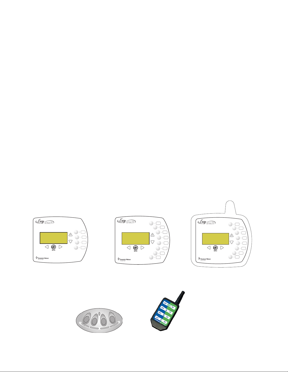
EasyTouch Accessory Equipment
iS4 Spa-Side Remote
Controller (P/N 520094)
QuickTouch Remote
Controller (P/N 520148)
EasyTouch 4 Indoor Control
Panel (P/N 520548)
EasyTouch 8 Indoor Control
Panel (P/N 520549)
POWER ON
EasyTouch Wireless Control Panel
(8 circuit) (P/N 520547)

2
EasyTouch Load Center Installation Guide
EasyTouch Accessory Equipment (continued)
EasyTouch Indoor Control Panel, 4 Circuits (P/N 520548)
EasyTouch Indoor Control Panel, 8 Circuits (P/N 520549)
EasyTouch Wireless Control Panel, 4 circuits (P/N 520546)
EasyTouch Wireless Control Panel, 8 circuits (P/N 520547)
iS4 Four-Function Spa-Side remote, 150 ft. cable (P/N 520094)
Two-Speed Three HP Relay up to three additional valve actuators (P/N 520198)
Three HP Power Relay (P/N 520106)
QuickTouch four-function wireless remote kit with transceiver assembly (P/N 520148)
IntelliChlor Acid Cleaning Kit (P/N 520670)
IntelliChlor Spacer pass-through cell for new pool start-up (P/N 520588)
EasyTouch System Installation Steps Summary
The recommended EasyTouch system installation steps are:
Prepare and install EasyTouch load center (pages 6-9): Review high voltage Load center
connections (see page 6). Prepare and install the EasyTouch load center at the equipment pad.
AC power for the EasyTouch load center must be provided from the main-panel located at the
house.
Remove EasyTouch load center knockouts/install conduit and wire to EasyTouch load
center (pages 10-11).
Install Auxiliary Relays and Valve Actuators (pages 15-16): Install auxiliary relays and the
valve actuators on the valve assembly and connect cables to the EasyTouch motherboard.
Install Temperature Sensors and Heat Thermostat (pages 17-18): Install the water and air
sensors and connect the cable plugs to the EasyTouch motherboard.
Connecting IntelliChlor cell (page 19): Connect the IntelliChlor cell to the EasyTouch load
Center. This optional equipment is include with IntelliChlor salt chlorine generator system only.
EasyTouch System Start-up (page 19): Perform a system start-up procedure.
Required Tools
• 5/16 in. diameter drill (for mounting water temperature sensor).
1
2
3
4
5
6

3
EasyTouch Load Center Installation Guide
Plumbing Requirements
It is important that the pool and spa plumbing system be in accordance with local codes and the
Recommended Hydraulic Schematics (page 4 and 5). Before starting, please review the diagrams
and the following recommended guidelines:
The spa should be at or above the level of the pool.
If the spa is attached to the pool, provide a dam between the two bodies of water to allow the spa
to overflow into the pool. If the spa is not attached to the pool, an overflow, sufficient in size to
carry a full pump-flow, must be installed at the water level in the spa.
Plumb a three-port Intake Valve on the suction-side of the filter pump, so that the center port of
the valve is connected to the pump inlet. Connect the spa suction to one side of the Intake Valve,
and the pool suction to the other side.
Plumb a three-port Return Valve on the return-side of the heater, so that the return water will
enter the valve through the center port.
Connect the spa return to one side of Return Valve, and the pool return to the other side.
If required, install a spa makeup line (consisting of a manual gate or ball valve, for elevated spas
install a check valve) to bypass the pool return line. This will enable some of the chemically-
balanced water from the pool to cycle through the spa. The manual valve will allow the amount of
bypass to be adjusted.
If the spa is to be constructed in concrete, special provision should be made at this time for the
installation of the Spa-Side remote control.
Select a convenient location in the deck or above water level in the spa wall (where the
Spa-Side remote will not be submerged by the spa water), and install a 6 in to 12 in length of
one inch PVC pipe to provide a receptacle for the Spa-Side remote. The pipe should be level
and protrude beyond the finished surface of the spa. It will be cut back later at installation time.
Reduce the pipe size down to ½ in or ¾ in conduit, and run it to the proposed Load/Power
Center location at the equipment pad. Use sweep elbows for turns.
The Spa-Side remote will not be installed until the spa construction is completed.
For systems which incorporate a skimmer, it is possible to balance the amount of suction
between the skimmer and main drain for maintenance purposes. This is easily accomplished by
installing a manual three-port mixing valve at the suction line. Plumb one port to the skimmer and
the other to the main drain.
If a “non-booster pump” pressure-side pool cleaner is being used, plumb a manual three-port
valve between the filter pump and filter, with the third port plumbed to the pool cleaner line, and
install a motorized two-port Pool Cleaner Valve at this line. The motorized valve will
automatically open whenever the Control System activates the pool cleaner.
If a booster pump pool cleaner is being used, plumb the booster pump so that its suction-side is
connected to the pool return, after the heater, and as close to the ground as practical.
1
2
3
4
5
6
7
8
4
EasyTouch Load Center Installation Guide
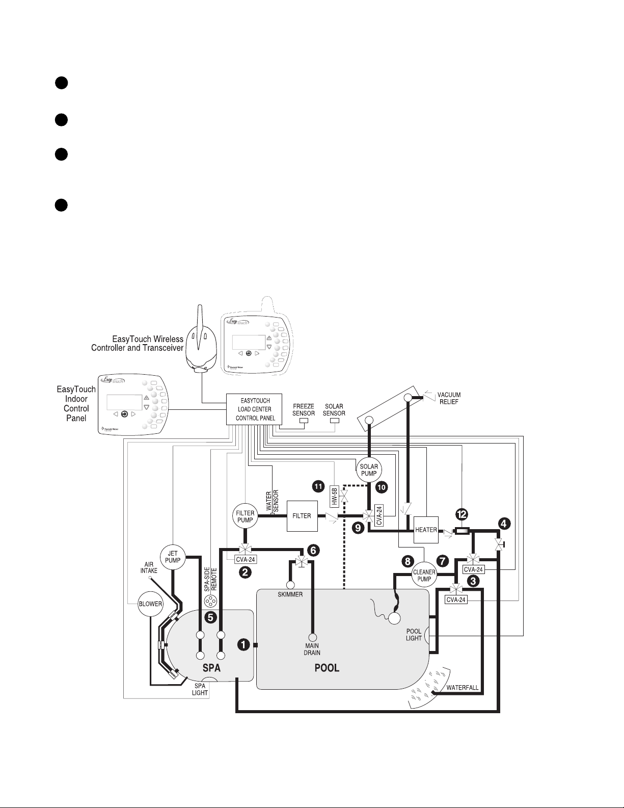
Recommended Hydraulic Schematic for Shared Equipment System
Plumb the solar feed and return lines between the filter and the heater. Install a three-port valve
at the feed line. Use a solar valve (model SOL-2T), to allow automatic draining of the panels.
A solar booster pump should be used when the distance to the panels exceed 200 ft., or the
panels are elevated higher than 25 ft.
Glazed solar panels require a drain valve (model HW-5B) to allow draining of the panels. This
prevents damage from overheating water. Install a drain valve at the solar feed line and connect
to the pool fill line.
SCG systems only: IntelliChlor cell with check valve between the heater and valves. Refer to
IntelliChlor User’s Guide (P/N 520589) page 4 for plumbing requirements.
Equipment Location
All equipment, with the exception of the spa-side remote, must be located at least 10 ft. from the
water’s edge.
9
10
11
INTELLICHLOR
12
 Loading...