


®
PT1250 Series
PT1250DC Series
PT1253R
PT1250 EX/AMS
PT1260EX Series
PT1280 Series
Heavy-Duty Pan/Tilts
Maintenance/
Service Manual
C373SM-A (8/01)
Pelco • 3500 Pelco Way, Clovis • CA 93612-5699 USA • www.pelco.com In North America and Canada: Tel (800) 289-9100 or FAX (800) 289-9150 International Customers: Tel +1 (559) 292-1981 or FAX +1 (559) 348-1120

CONTENTS |
|
|
Section |
Page |
|
IMPORTANT SAFEGUARDS AND WARNINGS ................................................................ |
4 |
|
DESCRIPTION ................................................................................................................... |
5 |
|
|
MODELS .................................................................................................................... |
5 |
|
OPTIONS ................................................................................................................... |
6 |
MAINTENANCE ................................................................................................................. |
7 |
|
|
TIGHTENING DRIVE CHAINS .................................................................................. |
7 |
|
CHAIN DRIVE LUBRICATION ................................................................................... |
7 |
Resetting Potentiometers ................................................................................................... |
8 |
|
|
MOTOR BRAKE REPLACEMENT ............................................................................. |
8 |
EXPLODED ASSEMBLY DIAGRAMS ................................................................................ |
9 |
|
WIRING DIAGRAMS ......................................................................................................... |
34 |
|
WARRANTY AND RETURN INFORMATION .................................................................... |
48 |
|
LIST OF ILLUSTRATIONS |
|
|
Figure |
Page |
|
1 |
Servicing the Pan/Tilt ......................................................................................... |
7 |
2 |
Sealant Locations .............................................................................................. |
8 |
3 |
PT1250 Series Exploded Assembly Diagram (Mechanical Parts) ..................... |
9 |
4 |
PT1250 Series Exploded Assembly Diagram (Hardware) ................................ |
12 |
5 |
PT1250DC Series Exploded Assembly Diagram .............................................. |
14 |
6 |
PT1253R Exploded Assembly (Mechanical Parts) ........................................... |
16 |
7 |
PT1253R Exploded Assembly (Hardware) ....................................................... |
18 |
8 |
PT1250EX/AMS Exploded Assembly Diagram ................................................. |
20 |
9 |
PT1260EX and PT1260EX/PP Exploded Assembly Diagram (Mechanical |
|
|
Parts) ................................................................................................................ |
23 |
10 |
PT1280P and PT1280SL Exploded Assembly (Mechanical Parts) ................... |
26 |
11 |
PT1280P and PT1280SL Exploded Assembly (Hardware) ............................... |
28 |
12 |
PT1280P/PP and PT1280SL/PP Exploded Assembly Diagram (Mechanical |
|
|
Parts) ................................................................................................................ |
30 |
13 |
PT1280P/PP and PT1280SL/PP Exploded Assembly (Hardware) ................... |
32 |
14 |
PT1250 Series Wiring for P, FG, FGP, HB and 220 Models ............................. |
34 |
15 |
PT1250 Series Wiring for RAD Model .............................................................. |
35 |
16 |
PT1250 Series Wiring for PP and WT Models .................................................. |
35 |
17 |
PT1250DC Wiring Diagram .............................................................................. |
36 |
18 |
PT1250DC/PP Wiring Diagram ......................................................................... |
37 |
19 |
PT1253R Schematic Diagram .......................................................................... |
38 |
20 |
12501007ACOMP Frame Scan Schematic ....................................................... |
39 |
21 |
PT1250EX/AMS Wiring Diagram ...................................................................... |
41 |
22 |
PT1260EX Wiring Schematic ............................................................................ |
42 |
23 |
PT1260EX/220 Wiring Diagram ........................................................................ |
42 |
24 |
PT1260EX/PP and PT1260EX/PP/230 Wiring Schematic ................................ |
43 |
25 |
PT1280P/PT128SL Wiring Diagram ................................................................. |
44 |
26 |
PT1280P/HB Wiring Diagram ........................................................................... |
45 |
27 |
PT1280P/PP Wiring Diagram ............................................................................ |
46 |
28 |
PT1280Sl/PP Wiring Diagram ........................................................................... |
47 |
2 |
Pelco Manual C373SM-A (8/01) |

LIST OF TABLES |
|
|
Table |
|
Page |
A |
PT1250 Series Mechanical Parts List ............................................................... |
10 |
B |
PT1250 Series Hardware List ........................................................................... |
13 |
C |
PT1250DC Series Parts List ............................................................................. |
15 |
D |
PT1253R Mechanical Parts List ........................................................................ |
17 |
E |
PT1253R Hardware List .................................................................................... |
19 |
F |
PT1250EX/AMS Parts List ................................................................................ |
21 |
G |
PT1260EX Series Mechanical Parts List .......................................................... |
24 |
H |
PT1260EX Series Hardware List ...................................................................... |
25 |
I |
PT1280P and PT1280SL Mechanical Parts List ............................................... |
27 |
J |
PT1280P and PT1280SL Hardware List ........................................................... |
29 |
K |
PT1280P/PP and PT1280SL/PP Mechanical Parts List ................................... |
31 |
L |
PT1280P/PP and PT1280SL/PP Hardware List ............................................... |
33 |
M |
PT1250 Series Electrical Parts List ................................................................... |
34 |
N |
PT1250DC Electrical Parts List ......................................................................... |
36 |
O |
PT1250DC/PP Electrical Parts List ................................................................... |
37 |
P |
12501007ACOMP Frame Scan Parts List ........................................................ |
40 |
Q |
PT1250EX/AMS Electrical Parts List ................................................................ |
41 |
Pelco Manual C373SM-A (8/01) |
3 |
IMPORTANT SAFEGUARDS AND WARNINGS
Prior to installation and use of this product, the following WARNINGS should be observed.
1.Installation and servicing should only be done by qualified service personnel and conform to all local codes.
2.Unless the unit is specifically marked as a NEMA Type 3, 3R, 3S, 4, 4X, 6 or 6P enclosure, it is designed for indoor use only and it must not be installed where exposed to rain and moisture.
3.Only use replacement parts recommended by Pelco.
4.The installation method and materials should be capable to supporting four times the weight of the enclosure, camera and lens combination.
5.The total load on tilt table shall not exceed 100 lb (45 kg) with the center of gravity at 5 inches above the tilt table surface. The weight and stiffness of explosion-proof cabling must be included in this weight calculation.
6.PT1250EX/AMS, PT1260EX Series Only–If used in marine applications, the installation shall be in accordance with the Electrical Engineering Regulations of the U.S.C.G., Subpart J, C.G. 259 (46 CFR Parts 110-113).
7.After replacement/repair of this unit’s electrical components, conduct a resistance measurement between line and exposed parts to verify the exposed parts have not been connected to line circuitry.
The product and/or manual may bear the following marks:
This symbol indicates that dangerous voltage constituting a risk of electric shock is present within this unit.
This symbol indicates that there are important operating and maintenance instructions in the literature accompanying this unit.
C A U T I O N :
RISK OF ELECTRIC SHOCK.
DO NOT OPEN.
Please thoroughly familiarize yourself with the information in this manual prior to installation and operation.
4 |
Pelco Manual C373SM-A (8/01) |

DESCRIPTION
All heavy duty pan/tilts can operate with loads up to 100 pounds (45.4 kg). Rugged hightorque motors with adjustable worm-gear final drives ensure long operational life and driftfree operation. All models are manufactured from cast and/or plate aluminum with all internal parts corrosion-protected steel or aluminum.
The PT1250 Series and PT1280 Series are capable of auto/random scan operation with the addition of the Pelco solid-state auto/random scan joystick control.
The PT1253R is equipped with variable frame scan capabilities (adjustable from 2-9 seconds) and interfaces with other manufacturers' control systems for frame scan operation. This pan/tilt can be used in place of the Vicon V390APT pan/tilt.
The PT1250EX/AMS meets the rigorous requirements for weather and dust-proof electrical equipment for installations in salt-air environments.
Pan/tilts in the PT1260EX Series meet the rigorous requirements of explosion-proof and dust-ignition-proof electrical equipment for installation and use in hazardous locations.
PT1260EX Series units are suitable for use in salty conditions such as aboard ships and on sea coasts.
MODELS
PT1250 Series |
|
PT1250P |
Heavy-duty, indoor/outdoor pan/tilt, 120 VAC |
PT1250P/220 |
Same as PT1250P except 230 VAC input |
PT1250P/FG |
Same as PT1250P except supplied with high-speed gears (12°/6° per |
|
sec pan/tilt speed). Reduces load to 50 lb (22.68 kg) |
PT1250P/FGP |
Same as PT1250P except supplied with special pan-speed gearing |
|
(12°/sec pan speed) |
PT1250P/HB |
Same as PT1250P except supplied with spot heaters in base, blanket |
|
heater in cover. Heaters are 120 VAC, 50/60 Hz, 230 watts total, and |
|
allow operation to -50°F (-46°C) |
PT1250P/HB/FG |
Combination of PT1250P/HB and PT1250P/FG |
PT1250P/PP |
Same as PT1250P except supplied with preset positioning option. |
|
Requires preset control or control with AZL option (position-indication |
|
meter) |
PT1250P/PP/WT |
Same as PT1250P/PP except white epoxy polyester powder coat finish |
PT1250P/RAD |
Same as PT1250P except supplied with radiation-resistant wiring and |
|
white epoxy paint. Low-level radiation resistancy |
PT1250DC Series |
|
PT1250DC |
Heavy duty, indoor/outdoor pan/tilt, 115 VDC |
PT1250DC/FG |
Same as PT1250DC except supplied with special high-speed gears |
|
(12°/6° per second pan/tilt speed). Reduces total load rating to 50 lb |
|
(22.68) |
PT1250DC/HB |
Same as PT1250DC except supplied with spot heater in base, blanket |
|
heater in cover, 120 VAC (230 watts total). Allows operation to |
|
-50°F (-46°C) |
Pelco Manual C373SM-A (8/01) |
5 |

PT1250DC/PP |
Same as PT1250DC except supplied with position feedback |
|
modification. Requires preset control or control with AZL option (panel |
|
readout meters) |
PT1250DC/RAD |
Same as PT1250DC except supplied with radiation resistant wiring and |
|
white epoxy paint. Low level radiation resistant up to 106 rads |
PT1253R |
|
PT1253R |
Heavy duty, indoor/outdoor pan/tilt, 120 VAC. Equipped with variable |
|
frame scan |
PT1250EX/AMS |
|
PT1250EX/AMS |
Heavy duty, indoor/outdoor pan/tilt, 120 VAC, Weather and dust-proof |
|
construction for installation in salt-air environments. |
PT1260EX Series |
|
PT1260EX |
Explosion-proof, 120 VAC operation pan/tilt for loads up to 100 lb (45 kg). |
PT1260EX/220 |
Same as PT1260EX except 230 VAC operation |
PT1260EX/PP |
Same as PT1260EX except supplied with preset position modification |
|
(PP) |
PT1260EX/PP/230 |
Same as PT1260EX/PP except 230 VAC operation |
PT1280 Series |
|
PT1280P |
Heavy duty indoor/outdoor pan/tilt, 120 VAC |
PT1208P/HB |
Same as PT1280P except supplied with spot heaters in base, blanket |
|
heater in cover, 230 watts total. 120 VAC, 50/60 Hz |
PT1280P/PP |
Same as PT1280P except with presets |
PT1280SL |
Heavy duty indoor/outdoor pan/tilt with SL option (360° pan rotation) |
PT1280SL/PP |
Same as PT1280SL except with presets |
OPTIONS
FGT/1250 |
Special tilt speed gearing: 6°/sec tilt speed. Reduces load to 50 lb |
|
(22.68 kg) |
FG/1250P |
High speed gears: 12°/sec pan, 6°/sec tilt. Reduces load to 50 lb |
|
(22.68 kg) |
FGP/1250P |
High speed gearing for pan: 12°/sec |
FGT/1250P |
High speed gearing for tilt: 6°/sec tilt. Reduces load to 50 lb (22.68 kg) |
SEC |
Sector scan modification allows pan/tilt to auto-scan and manually |
|
override in present sector (PT1280P) |
HB/1250 |
Spot heaters in base, blanket heater in cover. 230 watts total. 120 |
|
VAC, 50/60Hz allows operation to -50°F (-45.56°C) |
6 |
Pelco Manual C373SM-A (8/01) |

MAINTENANCE
Inspect the pan/tilt unit every six months to ensure trouble-free operation and an extended product life. Harsh environments and/or continuous motion applications may require more frequent maintenance.
Please read all of the instructions that follow before servicing the pan/tilt.
To begin, remove the three screws on the front of the pan/tilt housing and lift the cover to gain access to the pan and tilt motor assemblies.
TIGHTENING DRIVE CHAINS
Check the pan and tilt drive chains for tension. A movement of 1/32 of an inch to 3/32 of an inch in the chains is acceptable. If the movement of a chain exceeds 3/32 of an inch, adjust the chain as follows:
1.Loosen the screws securing the motor to the mounting frame.
2.Pry on the motor to apply tension to the chain. Do not over-tension the drive chain.
3.Keep tension on the chain while tightening the screws.
CHAIN DRIVE LUBRICATION
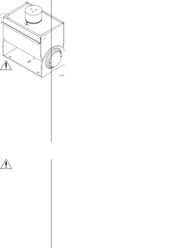
Sprockets, chains, and gears should be well greased. If necessary, lubricate the pan and tilt gears, sprockets, and chains as follows with a high-quality grease capable of withstanding temperatures from -50° to 170°F (-46° to 77°C). Do the following:
1.Liberally apply grease to the pan and tilt gears, chains, and sprockets (refer to Figure 1).
2.Operate the pan and tilt motors to spread the grease across the parts.
3.Apply additional grease if necessary.
4.Reinstall the cover. If the pan/tilt is installed outdoors in an inverted position, apply RTV silicone sealant as shown in Figure 2 (except PT1250EX/AMS and PT1260EX
Series).
Figure 1. Servicing the Pan/Tilt
Pelco Manual C373SM-A (8/01) |
7 |
RESETTING POTENTIOMETERS
IMPORTANT: Be very careful when resetting potentiometer switches. Be sure that the pan/tilt has been centered between maximum pan and tilt travel, regardless of the adjustable limit stops. Failure to observe caution when resetting potentiometers could result in damage to the preset positioning ability of the pan/tilt.
WARNING:
NEVER reposition the pan fixed limit stop. Doing so WILL DAM-
AGE the wiring harness and, if the pan/tilt has preset positioning, COULD cause the pan potentiometer to BREAK.
Models with Preset Positioning (PP)
Models with preset positioning (PP) use potentiometer switches that are factory set to the full range of pan and tilt travel. Under normal operating conditions and at routine service intervals they do not need adjusting.
Should your pan/tilt require any work on the drive mechanism other than routine maintenance, perform the following procedure to reset the potentiometers.
To begin, remove the cover to gain access to the pan and tilt motor assemblies.
1.Remove the potentiometer gears and position the pan/tilt to the middle of its maximum pan and tilt travel, regardless of the position of the adjustable limit stops. That is, the tilt table should be level and the fixed limit stop should be opposite the limit switch.
2.Turn a potentiometer all the way in one direction until it stops, then observing the number of turns, turn it
|
back the other way until it stops. |
|
|
|
Rotate the potentiometer half the |
||
|
number of turns the other way to |
|
|
|
reach the center. |
|
|
3. |
Replace the potentiometer gear. |
|
|
|
|||
|
|
||
4. |
Perform steps 2 and 3 for the other |
|
|
|
potentiometer. |
|
Figure 2. Sealant Locations
MOTOR BRAKE REPLACEMENT
WARNING: The knife-blade included in the brake
kit is very sharp. It should be handled carefully and disposed of properly after use.
NOTE: This section does not apply to the PT1250DC Series.
To order replacement motor brakes, specify part number 1250BRAKE. The kit consists of four springs, four Teflon pads, two screws, and a small knife-blade for removing the old brake pads.
1.Remove the large rectangular heat sink from the back of the pan motor. Remove the four springs. Do not disturb the silicone heat sink compound. It ensures the transfer of heat to the heat sink and MUST be present when the heat sink is replaced.
2.Use the knife blade to remove the worn pads, as follows:
a.Insert the knife blade into the opening and press firmly into the brake pad.
b.Before trying to remove the brake pad, twist the knife-blade. This will loosen the worn pad and make removal easier.
c.Gently twist the blade as you pull the worn pad out.
3.Insert the four new brake pads and four springs. Replace the heat sink using the new screws.
Reinstall the cover. If your pan/tilt is installed outdoors in an inverted position, apply RTV silicone sealant to the areas circled in Figure 2 (except PT1250EX/AMS and PT1260EX Series).
8 |
Pelco Manual C373SM-A (8/01) |
EXPLODED ASSEMBLY DIAGRAMS
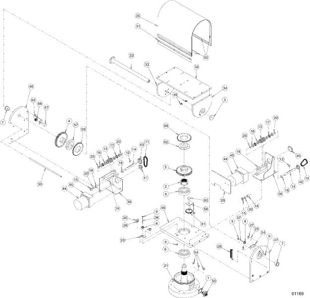
Figure 3. PT1250 Series Exploded Assembly Diagram (Mechanical Parts)
Pelco Manual C373SM-A (8/01) |
9 |
Table A. PT1250 Series Mechanical Parts List
Item |
Qty |
Description |
Part Number |
|
|
|
|
1 |
1 |
Gasket |
105010010 |
2 |
1 |
Pan spindle nut |
10504017COMP |
3 |
1 |
Thrust cap (except WT, RAD models) |
10504076COMP |
|
1 |
Thrust cap (WT and RAD only) |
10504076WCOMP |
4 |
1 |
Tilt gear |
10504084COMP |
5 |
1 |
Pan gear |
10504089COMP |
6 |
2 |
Bearing |
10506009 |
7 |
2 |
Bearing |
10506010 |
8 |
2 |
Grommet |
125010000 |
9 |
4 |
Retainer clip |
125010001 |
10 |
1 |
Pan chain assembly (except 220, FG, FGP models) |
12501010COMP |
|
1 |
Pan chain assembly (FG and FGP only) |
12501020COMP |
|
1 |
Pan chain assembly (220 only) |
12501221COMP |
11 |
1 |
Tilt chain assembly (except 220 , FG, FGP models) |
12501011COMP |
|
1 |
Tllt chain assembly (FG and FGP only) |
12501001COMP |
|
1 |
Tilt chain assembly (220 only) |
12501220COMP |
12 |
2 |
Key |
105010015 |
13 |
2 |
Worm gear |
105012010 |
14 |
2 |
Shaft (except 220 model) |
10504078COMP |
|
2 |
Shaft (220 only) |
20004110COMP |
15 |
2 |
Thrust collar |
10504085COMP |
16 |
8 |
Bearing washer |
10506005 |
17 |
4 |
Bearing cage |
10506006 |
18 |
4 |
Bearing |
10506007 |
19 |
2 |
Gear train bracket |
12504079COMP |
20 |
8 |
Arbor shim |
ZHSHIM.004 |
21 |
1 |
Spindle base assembly (except WT, RAD models) |
12501041ACOMP |
|
1 |
Spindle base assembly (WT and RAD only) |
12501041AWCOMP |
22 |
1 |
Tilt shaft assembly |
12501043COMP |
23 |
1 |
Pan limit bracket |
12504100COMP |
24 |
1 |
Tilt limit bracket |
1554052COMP |
25 |
4 |
Switch |
SWI1SM1 |
26 |
2 |
Pan switch actuator with insulation |
SWIJS221 |
27 |
2 |
Tilt switch actuator with insulation |
SWIJS138B |
28 |
1 |
9-pin terminal strip |
TRS2009 |
29 |
1 |
Heat sink (except 220, RAD models) |
12504010ACOMP |
30 |
2 |
Spacer rod |
12504110COMP |
31 |
1 |
Pull-up bar (except WT, RAD models) |
12504111COMP |
|
1 |
Pull-up bar (WT and RAD only) |
12504111WCOMP |
32 |
1 |
Tilt table top (except WT, RAD models) |
12504116COMP |
|
1 |
Tilt table top (WT and RAD only) |
12504116WCOMP |
33 |
1 |
Tilt table side (except WT, RAD models) |
12504117COMP |
|
1 |
Tilt table side (WT and RAD only) |
12504117WCOMP |
34 |
1 |
Tilt table side (limit stops) (except WT, RAD models) |
12504118COMP |
|
1 |
Tilt table side (limit stops) (WT and RAD only) |
12504118WCOMP |
35 |
1 |
Cover (except WT, RAD models) |
12504119BWA |
|
1 |
Cover (WT and RAD only) |
12504119WA |
36 |
1 |
Pan limit pin |
12504120ACOMP |
37 |
1 |
Tilt limit pin |
12504121ACOMP |
38 |
1 |
Pan motor plate (except 220 model) |
12504123COMP |
|
1 |
Pan motor plate (220 only) |
12504220COMP |
39 |
1 |
Tilt motor plate (except 220 model) |
12504123TCOMP |
|
1 |
Tilt motor plate (220 only) |
12504221COMP |
40 |
1 |
Pan motor sprocket (except 220, FG, FGP models) |
12504124COMP |
|
1 |
Pan motor sprocket (FG and FGP only) |
1504016 COMP |
|
1 |
Pan motor sprocket (220 only) |
12504226COMP |
41 |
1 |
Tilt motor sprocket (except 220, FG models) |
12504125COMP |
|
1 |
Tilt motor sprocket (220 only) |
28012011 |
|
1 |
Tilt motor sprocket (FG only) |
12504124COMP |
42 |
1 |
Pan sprocket |
12504126COMP |
|
|
|
|
Continued on next page
10 |
Pelco Manual C373SM-A (8/01) |
Table A. PT1250 Series Mechanical Parts List (Continued)
Item |
Qty |
Description |
Part Number |
|
|
|
|
43 |
1 |
Tilt sprocket (except 220, FG models) |
12504127COMP |
|
1 |
Tilt sprocket (220 only) |
12504227COMP |
|
1 |
Tilt sprocket (FG only) |
12504126COMP |
44 |
2 |
Motor, 120 VAC (except 220 model) |
12508110 |
|
2 |
Motor, 230 VAC (220 only) |
12508115 |
45 |
2 |
Gear head (except 220 model) |
12508111 |
|
2 |
Gear head (220 only) |
12508114 |
46 |
1 |
Bottom plate |
12504112ACOMP |
47 |
1 |
Side plate, tilt side (except WT, RAD models) |
12504115COMP |
|
1 |
Side plate, tilt side (WT and RAD only) |
12504115WCOMP |
48 |
1 |
Side plate, pan side (except WT, RAD models) |
12504114ACOMP |
|
1 |
Side plate, pan side (WT and RAD only) |
12504114AWCOMP |
49 |
2 |
Tilt limit stop |
1554055COMP |
50 |
1 |
7-pin male connector (RAD model) |
MS3102E16S1P |
|
1 |
9-pin male connector (P, 220, FG, FGP models) |
CON206705-1 |
|
1 |
16-pin male connector (PP, WT, HB models) |
CON206036-1 |
51 |
|
Not used |
|
52 |
7 |
Gasket, 1/8" x 1/2" x feet (except FG, FGP models) |
EH550010030 |
|
2 |
Gasket, 1/8" x 1/2" x feet (FG and FGP only) |
EH550010030 |
53 |
|
Not used |
|
54 |
3 |
Pan limit stop |
58010006 |
55 |
|
Not used |
|
56 |
|
Not used |
|
|
|
The following items are for the PP and WT models only: |
|
57 |
1 |
Collar, tilt AZL gear |
12504020COMP |
58 |
1 |
AZL potentiometer bracket |
12504003COMP |
59 |
1 |
Gear, AZL collar |
12504104 |
60 |
1 |
Potentiometer, 5K ohm |
POT005.0K10534 |
61 |
1 |
Gear potentiometer |
TV12000 |
62 |
1 |
Collar, pan AZL gear |
12504001COMP |
63 |
|
Not used |
|
64 |
|
Not used |
|
65 |
1 |
AZL potentiometer bracket |
12504003COMP |
66 |
1 |
Gear |
TV12000 |
67 |
1 |
Potentiometer, 5K ohm |
POT005.0K10534 |
68 |
1 |
Gear, AZL collar |
12504104 |
|
|
The following items are for the HB model only but are |
|
|
|
not shown: |
|
|
1 |
Cover heater blanket, 120 VAC |
105010000 |
|
2 |
Base heater blanket, 120 VAC |
EH110065A |
|
1 |
Thermostat |
EH5510049A |
|
|
|
|
Pelco Manual C373SM-A (8/01) |
11 |
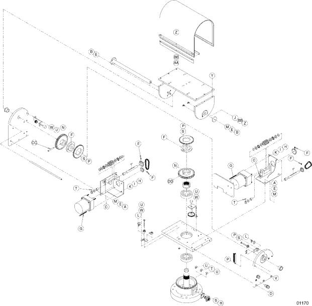
Figure 4. PT1250 Series Exploded Assembly Diagram (Hardware)
12 |
Pelco Manual C373SM-A (8/01) |
Table B. PT1250 Series Hardware List
Item |
Qty |
|
Description |
Part Number |
|
|
|
|
|
A |
4 |
Screw, 1/4-20 x 1/2" |
ZH1/420X.500CH |
|
B |
5 |
Allen bolt, 1/4-20 x 5/8" |
ZH1/420X.625CS |
|
C |
4 |
Bolt, 1/4-20 x 3/4" |
ZH1/420X.750CH |
|
D |
6 |
Screw 1/4-20 x 1", flat-head, Phillips |
ZH1/420X1.00SFS |
|
E |
9 |
Split lock washer, 1/4" |
ZH1/4LWSSL |
|
F |
4 |
Set screw, 10-32 x 3/16" (except PP, WT models) |
ZH10-32X.187S |
|
|
6 |
Set screw, 10-32 x 3/16" (PP and WT only) |
ZH10-32X.187S |
|
G |
8 |
Screw, 10-32 x 2 1/4", pan head, Phillips |
ZH10-32X2.25SPS |
|
H |
8 |
Nut, 10-32 |
|
ZH10-32NUTSH |
I |
8 |
Split lock washer, #10 |
ZH10LWSSL |
|
J |
2 |
Flat washer, #8 |
ZH188X435X60C |
|
K |
8 |
Flat washer, #10 |
ZH204X436X60C |
|
L |
8 |
Screw, 2-56 x 7/16", pan head, Phillips |
ZH2-56X.437SPP |
|
M |
5 |
Flat washer, 3/16" |
ZH260X562X65C |
|
N |
2 |
Set screw, 3/8-24 x 3/8" |
ZH3/8-24X.375S |
|
P |
4 |
Screw, 4-40 x 1/4", pan head, Phillips (except PP, WT) |
ZH4-40X.250SPP |
|
|
8 |
Screw, 4-40 x 1/4", pan head, Phillips (PP, WT only) |
ZH4-40X.250SPP |
|
R |
4 |
Screw, 4-40 x 3/8", pan head, Phillips |
ZH4-40X.375SPP |
|
S |
6 |
Internal tooth lock washer, #4 (except PP, WT) |
ZH4LWSIS |
|
|
10 |
Internal tooth lock washer, #4 (PP and WT only) |
ZH4LWSIS |
|
T |
3 |
Set screw, 6-32 x 3/16" |
ZH6-32X.187S |
|
U |
4 |
Screw, 6-32 x |
3/8", pan head, Phillips (except PP, WT) |
ZH6-32X.375SPP |
|
6 |
Screw, 6-32 x |
3/8", pan head, Phillips (PP, WT only) |
ZH6-32X.375SPP |
V |
4 |
Screw, 6-32 x 3/4" flat head, Phillips |
ZH6-32X.750SFS |
|
W |
2 |
Split lock washer, #6 (except PP, WT) |
ZH6LWSIS |
|
|
6 |
Split lock washer, #6 (PP and WT only) |
ZH6LWSIS |
|
X |
|
Not used |
|
|
Y |
6 |
Allen screw, 8-32 x 1/2" |
ZH8-32X.500CS |
|
Z |
5 |
Screw, 8-32 x 5/8", pan head, Phillips |
ZH8-32X.625SPP |
|
AA |
3 |
Nut, 8-32 |
|
ZH8-32NUTSH |
BB |
5 |
Internal star washer, #8 |
ZH8LWSIS |
|
CC |
1 |
Tapered pin, #5 x 2 1/2" |
105010017 |
|
DD |
1 |
Dowel pin, 3/16" x 5/8" |
ZHPIN3/16X5/8 |
|
|
|
|
|
|
Pelco Manual C373SM-A (8/01) |
13 |

Figure 5. PT1250DC Series Exploded Assembly Diagram
14 |
Pelco Manual C373SM-A (8/01) |
Table C. PT1250DC Series Parts List
Item |
Qty |
Description |
Part Number |
|
|
|
|
1 |
1 |
Gasket connector |
105010010 |
2 |
1 |
Pin tapper #5 x 2" |
105010017 |
3 |
1 |
Nut, pan spindle |
10504017COMP |
4 |
1 |
Thrust cap |
10504076COMP |
5 |
1 |
Gear tilt |
10504084COMP |
6 |
2 |
Thrust collar |
10504085COMP |
7 |
1 |
Gear, pan |
10504089COMP |
8 |
– |
(Not used) |
|
9 |
2 |
Bearing |
10506009 |
10 |
2 |
Bearing |
10506010 |
11 |
2 |
Mount limit pin |
125010000 |
12 |
4 |
Clip retainer |
125010001 |
13 |
1 |
Chain assembly, pan motor |
12501000COMP |
14 |
1 |
Chain assembly, tilt motor |
12501001COMP |
15 |
2 |
PC board assembly filter |
12501003COMP |
16 |
2 |
Key, Woodruff #3 |
105010015 |
17 |
2 |
Gear, worm pan/tilt |
105012010 |
18 |
8 |
Bearing, A016 washer only |
10506005 |
19 |
4 |
Bearing, A016C cage only |
10506006 |
20 |
6 |
Bearing |
10506007 |
21 |
2 |
Bracket, gear train |
12504079COMP |
22 |
2 |
Shaft, gear train |
20004110COMP |
23 |
1 |
Bearing, boss |
10504069COMP |
24 |
1 |
Bottom plate |
12504113ACOMP |
25 |
1 |
Pan side plate |
12504114ACOMP |
26 |
1 |
Tilt side plate |
12504115ACOMP |
27 |
1 |
Spindle |
10504074COMP |
28 |
1 |
Base |
12504112ACOMP |
29 |
1 |
Flange, tilt |
10504077COMP |
30 |
1 |
Shaft, tilt (less flange) |
12504122COMP |
31 |
1 |
Plate, pan motor |
12504006COMP |
32 |
1 |
Plate, tilt motor |
12504007COMP |
33 |
2 |
Bracket, circuit board |
12504009COMP |
34 |
2 |
Spacer, rod |
12504110COMP |
35 |
1 |
Pull-up bar |
12504111COMP |
36 |
1 |
Tilt table top |
12504116COMP |
37 |
1 |
Table, side tilt 4H |
12504117COMP |
38 |
1 |
Table, side tilt 1H |
12504118COMP |
39 |
1 |
Cover |
12504119BWA |
40 |
1 |
Pin limit, pan |
12504120ACOMP |
41 |
1 |
Pin limit, tilt |
12504121ACOMP |
42 |
2 |
Sprocket, pan gear train |
12504126ACOMP |
43 |
2 |
Sprocket, tilt gear train |
12504127ACOMP |
44 |
2 |
Motor |
MR02-0002-3104 |
45 |
2 |
Tilt limit stop |
1554050COMP |
46 |
2 |
Bracket, tilt limit |
1554052COMP |
47 |
3 |
Limit stop pan, univ pan/tilt |
58010006 |
48 |
4 |
Spacer, 1/4 O.D. x .375 ##6, clear |
SPA2101 |
49 |
4 |
Switch |
SWI1SM1 |
50 |
2 |
Pan switch actuator w/insulator |
SWIJS138B |
|
2 |
Tilt switch actuator w/insulator |
SWIJS221 |
51 |
4 |
Screw, 1/4-20 x 1/2" Hex CAD |
ZH1/4-20X.500CH |
52 |
5 |
Bolt, 1/4-20 x 5/8" SOC SS |
ZH1/420X.625CS |
53 |
4 |
Bolt, 1/4-20 x 3/4" Hex CAD |
ZH1/420X.750CH |
54 |
6 |
Screw, 1/4-20 x 1" Flat slot SS |
ZH1/420X1.00SFS |
|
|
|
|
Pelco Manual C373SM-A (8/01) |
15 |
 Loading...