


Installation and Assembly:
OneMount™
Models: ONE-TP, ONE-TP-S, RTONE, RTONES
R
This product is UL Listed. It must be installed by a qualified professional installer.
Max UL Load Capacity 250lb (113.5kg)
Features:
•Fits 23" to 84" flat panel screens
•Easily expandable adapter brackets and wall plate
•Adjustable tilt of +15°/-5° for viewing flexibility
•Intuitive design for easy installation
•Security hardware for theft resistance and safety
3215 W. North Ave. • Melrose Park, IL 60160 • (800) 729-0307 or (708) 865-8870 • Fax: (708) 865-2941 • www.peerlessmoun ts.com

Note: Read entire instruction sheet before you start installation and assembly.
 WARNING
•Do not begin to install your Peerless product until you have read and understood the instructions and warnings contained in this Installation Sheet. If you have any questions regarding any of the instructions or warnings, please call Peerless customer care at 1-800-729-0307.
•This product should only be installed by someone of good mechanical aptitude, has experience with basic building construction, and fully understands these instructions.
•Make sure that the supporting surface will safely support the combined load of the equipment and all attached hardware and components.
•Never exceed the Maximum UL Load Capacity. See page one.
•If mounting to wood wall studs, make sure that mounting screws are anchored into the center of the studs. Use of an "edge to edge" stud finder is highly recommended.
•Always use an assistant or mechanical lifting equipment to safely lift and position equipment.
•Tighten screws firmly, but do not overtighten. Overtightening can damage the items, greatly reducing their holding power.
Tools Needed for Assembly |
|
|
• |
stud finder ("edge to edge" stud finder is recommended) |
|
• |
phillips screwdriver |
|
• |
drill |
|
• |
1/4" bit for concrete and cinder block wall |
|
• |
5/32" bit for wood stud wall |
|
• |
level |
|
• |
7/16" socket or crescent wrench |
|
• |
tape measure |
|
Accessories: |
|
|
• ACC927, ACC927-S |
|
|
Table of Contents |
|
|
Parts List .............................................................................................................................................................................. |
3 |
|
Adjusting Tilt Brackets .......................................................................................................................................................... |
4 |
|
Attaching Tilt Brackets to Screen using Baffled Fastener Pack ............................................................................................ |
5 |
|
Installation to Double Wood Stud Wall .................................................................................................................................. |
8 |
|
Installation to Triple Wood Stud Wall .................................................................................................................................... |
9 |
|
Installation to Solid Concrete or Cinder Block ..................................................................................................................... |
10 |
|
Mounting and Removal of Flat Panel Screen ....................................................................................................................... |
11 |
|
For customer care call (800) 729-0307 or (708) 865-8870.
2 of 33 |
ISSUED: 09-20-06 SHEET #: 202-9167-3 01-26-07 |
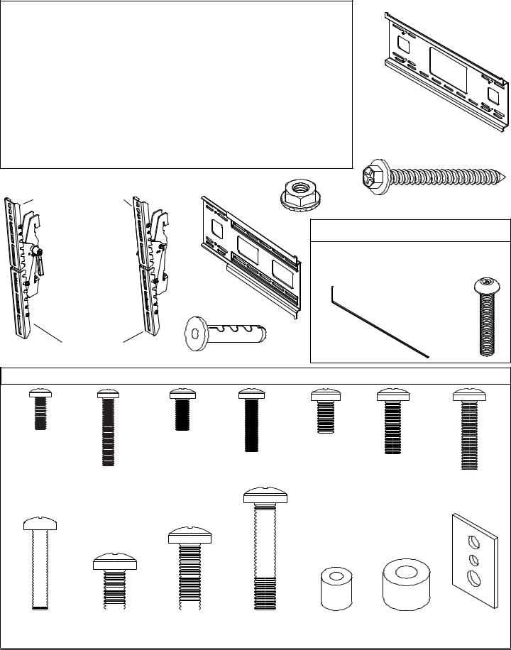
Before you begin, make sure all parts shown are included with your product.
Parts may appear slightly different than illustrated.
Parts List
|
|
|
Black |
Silver |
|
Description |
Qty. |
Part # |
Part# |
AA wall plate |
1 |
201-1210 |
201-4210 |
|
BB left tilt bracket |
1 |
201-0181 |
201-0192 |
|
CC right tilt bracket |
1 |
201-0177 |
201-0193 |
|
DD #14 x 2.5 wood screw |
6 |
5S1-015-C03 |
5S1-015-C03 |
|
EE Alligator® anchor |
6 |
590-0097 |
590-0097 |
|
F F 1/4" serrated flanged locknut |
4 |
530-1021 |
530-1021 |
|
GG wing bracket |
2 |
201-1134 |
201-4134 |
|
HH |
M5 x 30 mm security screw |
2 |
520-1112 |
520-1112 |
II |
wrench |
1 |
560-1146 |
560-1146 |
AA
DD
BB |
CC GG |
FF |
|
top extension bracket |
|
Security Option
NOTE: Replace safety screw in each tilt bracket with M5 x 30 security screw (HH) using wrench (II).
II |
HH |
EE |
|
bottom extension bracket
Adapter Bracket Fasteners
M4 x 12 mm (6) |
M5 x 12 mm (4) |
M6 x 12 mm (4) |
|
(504-9013) |
(520-1027) |
||
(520-1128) |
|||
|
M5 x 25 mm (4) |
||
|
M6 x 20 mm (4) |
||
M4 x 25 mm (4) |
(520-9543) |
(520-9402) M6 x 25 mm (4) |
|
|
|||
(504-1015) |
|
(520-1208) |
|
|
|
|
|
|
|
|
|
|
|
|
|
|
|
|
|
|
|
|
|
|
|
|
|
|
|
|
|
|
|
|
|
|
|
|
|
|
|
|
|
|
|
|
|
|
|
|
|
|
|
|
|
|
|
|
|
|
|
|
|
|
|
|
|
|
|
|
|
|
|
|
|
|
|
|
|
|
|
|
|
|
|
|
|
|
|
|
|
|
|
|
|
|
|
|
|
|
|
|
|
|
|
|
|
|
|
|
|
|
|
|
|
|
|
|
|
|
|
|
|
|
|
|
|
|
|
|
|
|
|
|
|
|
|
|
|
|
|
|
|
|
|
|
|
|
|
|
|
|
|
|
|
|
|
|
|
|
|
|
|
|
|
|
|
|
|
|
|
|
|
|
|
|
|
|
|
|
|
|
|
|
|
|
|
|
|
|
|
|
|
|
|
|
|
|
|
|
|
|
|
|
|
|
|
|
|
|
|
|
|
|
|
|
|
|
|
|
|
|
|
|
|
|
|
|
|
|
|
|
|
|
|
|
|
|
|
|
|
|
|
|
|
|
|
|
|
|
|
|
|
|
|
|
|
|
|
|
|
|
|
|
|
|
|
|
|
|
|
|
|
|
|
|
|
|
|
|
|
|
|
|
|
|
|
|
|
|
|
|
|
|
|
|
|
|
|
|
|
|
|
|
|
|
|
|
|
|
|
|
|
|
|
|
|
|
|
|
|
|
|
|
|
|
|
|
|
|
|
|
|
|
|
|
|
|
|
|
|
|
|
|
|
|
|
|
|
|
|
|
|
|
|
|
|
|
|
|
|
|
|
|
|
|
|
|
|
|
|
|
|
|
|
|
|
|
|
|
|
|
|
|
|
|
|
|
|
|
|
|
|
|
|
|
|
|
|
|
|
|
|
|
|
|
|
|
|
|
|
|
|
|
|
|
|
|
|
|
|
|
|
|
|
|
|
|
|
|
|
|
|
|
|
|
|
|
|
|
|
|
|
|
|
|
|
|
|
|
|
|
|
|
|
|
|
|
|
|
|
|
|
|
|
|
|
|
|
|
|
|
|
|
|
|
|
|
|
|
|
|
|
|
|
|
|
|
|
|
|
|
|
|
|
|
|
|
|
|
|
|
|
|
|
|
|
|
|
|
|
|
|
|
|
|
|
|
|
|
|
|
|
|
|
|
|
|
|
|
|
|
|
|
|
|
|
|
|
|
|
|
|
|
|
|
|
|
|
|
|
|
|
|
|
|
|
|
|
|
|
|
|
|
|
|
|
|
|
|
|
|
|
|
|
|
|
|
|
|
|
|
|
|
|
|
|
|
|
|
|
|
|
|
|
|
|
|
|
|
|
|
|
|
|
|
|
|
|
|
|
|
|
|
|
|
|
|
|
|
|
|
|
|
|
|
|
|
|
|
|
|
|
|
|
|
|
|
|
|
|
|
|
|
|
|
|
|
|
|
|
|
|
|
|
|
|
|
|
|
|
|
|
|
|
|
|
|
|
|
|
|
|
|
|
|
|
|
|
|
|
|
|
|
|
|
|
|
|
|
|
|
|
|
|
|
|
|
|
|
|
|
|
|
|
|
|
|
|
|
|
|
|
|
|
|
|
|
|
|
|
|
|
|
|
|
|
|
|
|
|
|
|
|
|
|
|
|
|
|
|
|
|
|
|
|
|
|
|
|
|
|
|
|
|
|
|
|
|
|
|
|
|
|
|
|
|
|
|
|
|
|
|
|
|
|
|
|
|
|
|
|
|
|
|
|
|
|
|
|
|
|
|
|
|
|
|
|
|
|
|
|
|
|
|
|
|
|
|
|
|
|
|
|
|
|
|
|
|
|
|
|
|
|
|
|
|
|
|
|
|
|
|
|
|
|
|
|
|
|
|
|
|
|
|
|
|
|
|
|
|
|
|
|
|
|
|
|
|
|
|
|
|
|
|
|
|
|
|
|
|
|
|
|
|
|
|
|
|
|
|
|
|
|
|
|
|
|
|
|
|
|
|
|
|
|
|
|
|
|
|
|
|
|
|
|
|
|
|
|
|
|
|
|
|
|
|
|
|
|
|
|
|
|
|
|
|
|
|
|
|
|
|
|
|
|
|
|
|
|
|
|
|
|
|
|
|
|
|
|
|
|
|
|
|
|
|
|
|
|
|
|
|
|
|
|
|
|
|
|
|
|
|
|
|
|
|
|
|
|
|
|
|
|
|
|
|
|
|
|
|
|
|
|
|
|
|
|
|
|
|
|
|
|
|
|
|
|
|
|
|
|
|
|
|
|
|
|
|
|
|
|
|
|
|
|
|
|
|
|
|
|
|
|
|
|
|
|
|
|
|
|
|
|
|
|
|
|
|
|
|
|
|
|
|
|
|
|
|
|
|
|
|
|
|
|
|
|
|
|
|
|
|
|
|
|
|
|
|
|
|
|
|
|
|
|
|
|
|
|
|
|
|
|
|
|
|
|
|
|
|
|
|
|
|
|
|
|
|
|
|
|
|
|
|
|
|
|
|
|
|
|
|
|
|
|
|
|
|
|
|
|
|
|
|
|
|
|
|
|
|
|
|
|
|
|
|
|
|
|
|
|
|
|
|
|
|
|
|
|
|
|
|
|
|
|
|
|
|
|
|
|
|
|
|
|
|
|
|
|
|
|
|
|
|
|
|
|
|
|
|
|
|
|
|
|
|
|
|
|
|
|
|
|
|
|
|
|
|
|
|
|
|
|
|
|
|
|
|
|
|
|
|
|
|
|
|
|
|
|
|
|
|
|
|
|
|
|
|
|
|
|
|
|
|
|
|
|
|
|
|
|
|
|
|
|
|
|
|
|
|
|
|
|
|
|
|
|
|
|
|
|
|
|
|
|
|
|
|
|
|
|
|
|
|
|
|
|
|
|
|
|
|
|
|
|
|
|
|
|
|
|
|
|
|
|
|
|
|
|
|
|
|
|
|
|
|
|
|
|
|
|
|
|
|
|
|
|
|
|
|
|
|
|
|
|
|
|
|
|
|
|
|
|
|
|
|
|
|
|
|
|
|
|
|
|
|
|
|
|
|
|
|
|
|
|
|
|
|
|
|
|
|
|
|
|
|
|
|
|
|
|
|
|
|
|
|
|
|
|
|
|
|
|
|
|
|
|
|
|
|
|
|
|
|
|
|
|
|
|
|
|
|
|
|
|
|
|
|
|
|
|
|
|
|
|
|
|
|
|
|
|
|
|
|
|
|
|
|
|
|
|
|
|
|
|
|
|
|
|
|
|
|
|
|
|
|
|
|
|
|
|
|
|
|
|
|
|
|
|
|
|
|
|
|
|
|
|
|
|
|
|
|
|
|
|
|
|
|
|
|
|
|
|
|
|
|
|
|
|
|
|
|
|
|
|
|
|
|
|
|
|
|
|
|
|
|
|
|
|
|
|
|
|
|
|
|
|
|
|
|
|
|
|
|
|
|
|
|
|
|
|
|
|
|
|
|
|
|
|
|
|
|
|
|
|
|
|
|
|
|
|
|
|
|
|
|
|
|
|
|
|
|
|
|
|
|
|
|
|
|
|
|
|
|
|
|
|
|
|
|
|
|
|
|
|
|
|
|
|
|
|
|
|
|
|
|
|
|
|
|
|
|
|
|
|
|
|
|
|
|
|
|
|
|
|
|
|
|
|
|
|
|
|
|
|
|
|
|
|
|
|
|
|
|
|
|
|
|
|
|
|
|
M8 x 40 mm (4) |
I.D. |
5.6 mm |
(4) |
|
|
|
|
|
|
||||
|
|
|
|
|
|
|
|
|
|
|
|
|
|
|
|
|
|
|
|
|
|
|
|
|
|
|
|
|
||||||||
|
|
|
|
|
|
|
|
|
|
|
|
|
|
|
|
|
|
|
|
|
|
|
|
|
|
|
|
|
||||||||
|
|
|
|
|
|
|
|
|
|
|
|
|
|
|
|
|
|
|
|
|
|
|
|
|
|
|
|
|
||||||||
|
|
|
|
|
|
|
|
|
|
|
|
|
|
|
|
|
|
|
|
|
|
|
|
|
|
|
|
|
||||||||
|
|
|
|
|
|
|
|
|
|
|
|
|
|
|
|
|
|
|
|
|
|
|
|
|
|
|
|
|
||||||||
|
|
|
|
|
|
|
|
|
|
|
|
|
|
|
|
|
|
|
|
|
|
|
|
|
|
|
|
|
||||||||
|
|
|
|
|
|
|
|
|
|
|
|
|
|
|
|
|
|
|
|
|
|
|
|
|
|
|
|
|
||||||||
|
|
|
|
|
|
|
|
|
|
|
|
|
|
|
|
|
|
|
|
|
|
|
|
|
|
|
|
|
||||||||
|
|
|
|
|
|
|
|
|
|
|
|
|
|
|
|
|
|
|
|
|
|
|
|
|
|
|
|
|
||||||||
|
|
|
|
|
|
|
|
|
|
|
|
|
|
|
|
|
|
|
|
|
|
|
|
|
|
|
|
|
||||||||
|
|
|
|
|
|
|
|
|
|
|
|
|
|
|
|
|
|
|
|
|
|
|
|
|
|
|
|
|
||||||||
|
|
|
|
|
|
|
|
|
|
|
|
|
|
|
|
|
|
|
|
|
|
|
|
|
|
|
|
|
||||||||
|
|
|
|
|
|
|
|
|
|
|
|
|
|
|
|
|
|
|
|
|
|
|
|
|
|
|
|
|
||||||||
|
|
|
|
|
|
|
|
|
|
|
|
|
|
|
|
|
|
|
|
|
|
|
|
|
|
|
|
|
||||||||
|
|
|
|
|
|
|
|
|
|
|
|
|
|
|
|
|
|
|
|
|
|
|
|
|
|
|
|
|
||||||||
|
|
|
|
|
|
|
|
|
|
|
|
|
|
|
|
|
|
|
|
|
|
|
|
|
|
|
|
|
||||||||
|
|
|
|
|
|
|
|
|
|
|
|
|
|
|
|
|
|
|
|
|
|
|
|
|
|
|
|
|
||||||||
|
|
|
|
|
|
|
|
|
|
|
|
|
|
|
|
|
|
|
|
|
|
|
|
|
|
|
|
|
||||||||
|
|
|
|
|
|
|
|
|
|
|
|
|
|
|
|
|
|
|
|
|
|
|
|
|
|
|
|
|
||||||||
|
|
|
|
|
|
|
|
|
|
|
|
|
|
|
|
|
|
|
|
|
|
|
|
|
|
|
|
|
||||||||
|
|
|
|
|
|
|
|
|
|
|
|
|
|
|
|
|
|
|
|
|
|
|
|
|
|
|
|
|
||||||||
|
|
|
|
|
|
|
|
|
|
|
|
|
|
|
|
|
|
|
|
|
|
|
|
|
|
|
|
|
||||||||
|
|
|
|
|
|
|
|
|
|
|
|
|
|
|
|
|
|
|
|
|
|
|
|
|
|
|
|
|
||||||||
|
|
|
|
|
|
|
|
|
|
|
|
|
|
|
|
|
|
|
|
|
|
|
|
|
|
|
|
|
||||||||
|
|
|
|
|
|
|
|
|
|
|
|
|
|
|
|
|
|
|
|
|
|
|
|
|
|
|
|
|
||||||||
M6 |
|
|
|
|
|
|
|
(4) |
|
|
|
|
|
|
|
|
|
|
|
|
|
|
I.D. 8.7 mm (4) |
multi-washer (6) |
||||||||||||
|
x 30 mm |
|||||||||||||||||||||||||||||||||||
|
M8 x 16 mm |
(6) |
|
|
|
|
|
|
|
|||||||||||||||||||||||||||
|
M8 x 25 mm |
(4) |
||||||||||||||||||||||||||||||||||
(510-9109) |
(520-9257) |
|
(520-1031) |
|
(520-1136) |
(540-1057) |
(540-1059) |
|
(580-1036) |
|
||||||||||||||||||||||||||
Parts may appear slightly different than illustrated.
3 of 33 |
ISSUED: 09-20-06 SHEET #: 202-9167-3 01-26-07 |
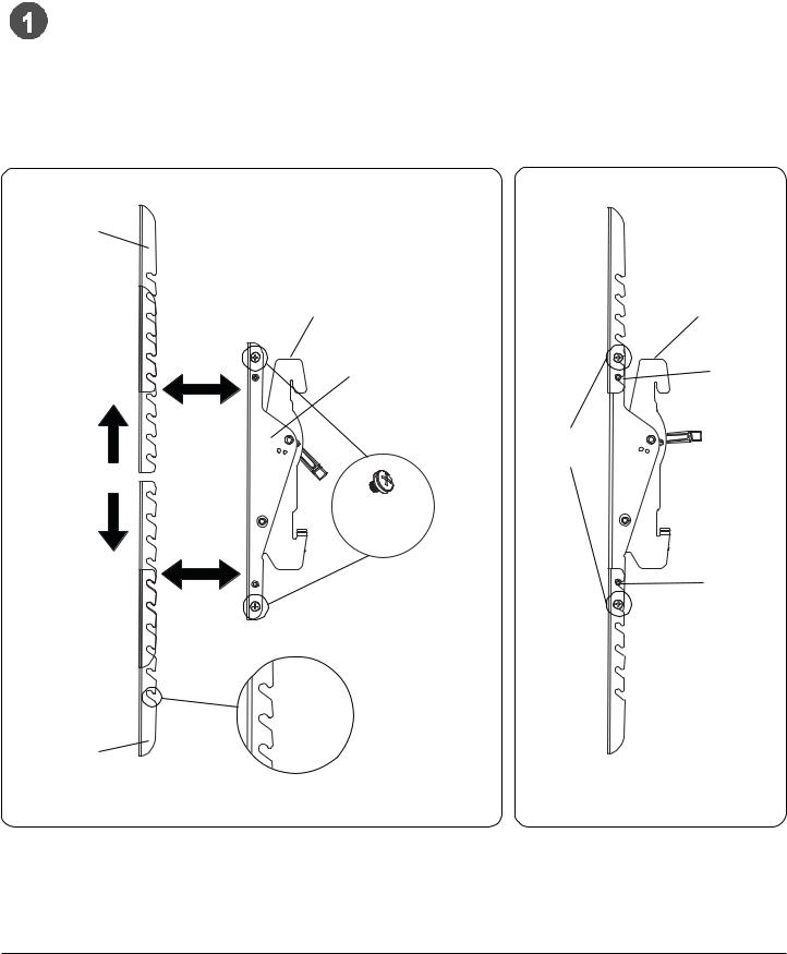
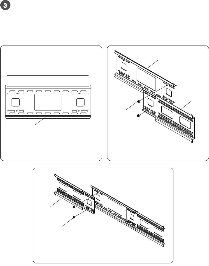
Adjustment of Extension Brackets
Loosen four 1/4-20 x 1/4" screws on each adapter bracket (BB,CC). Position extension brackets, with slots facing downward, onto adapter brackets (BB,CC) at the appropriate position to accommodate your screen as shown in Figure 1.1. Securely tighten all 1/4-20 x 1/4" screws as shown in figure 1.2.
NOTE: In all bracket extension positions, stops and 1/4-20 x 1/4" screws must be engaged in slots as shown in figure 1.2.
TOP EXTENSION BRACKET
BOTTOM EXTENSION BRACKET
BB,CC |
BB,CC |
ADAPTER |
STOP |
BRACKET |
|
|
TIGHTEN |
|
FASTENERS |
1/4-20 x 1/4" SCREWS
STOP
Make sure slots face downward.
fig 1.1 |
fig 1.2 |
4 of 33 |
ISSUED: 09-20-06 SHEET #: 202-9167-3 01-26-07 |
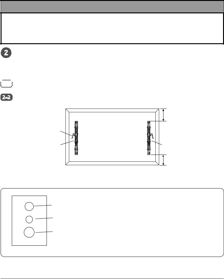
Attaching Tilt Brackets to Screen using Baffled Fastener Pack
 WARNING
•Tighten screws so adapter brackets are firmly attached. Do not tighten with excessive force. Overtightening can cause stress damage to screws, greatly reducing their holding power and possibly causing screw heads to become detached. Tighten to 40 in. • lb (4.5 N.M.) maximum torque.
•If screws don't get three complete turns in the screen inserts or if screws bottom out and bracket is still not tightly secured, damage may occur to screen or product may fail.
 NOTE: Refer to page 4 for adjustments of top extension bracket.
To prevent scratching the screen, set a cloth on a flat, level surface that will support the weight of the screen. Place screen face side down. Refer to screen manufacturers instructions or customer service, for removing any knobs, base, cover, or screw(s) on the back of the screen to prepare mounting. These need to be removed to allow the adapter brackets to be attached. Select the small, medium, large or extra large screws from the baffled fastener pack then attach tilt brackets to screen following figure 2.3 or 2.4.


 NOTE: Be sure to attach tilt brackets with knobs facing outward as in figure 2.1.


 NOTE: Top and bottom mounting holes must be used for attaching brackets. Middle holes should also be used where the


 fasteners and screens allow. Verify that all holes are properly aligned, and then tighten screws using a phillips screwdriver.
X
KNOBS FACE OUT |
CENTERBRACKETS |
|
VERTICALLY ON |
|
BACK OF SCREEN |
BB 
 CC
CC
X
Note: "X" dimensions should be equal. |
fig 2.1 |
MULTI-WASHER
MEDIUMHOLEFORM5SCREWS
SMALL HOLE FOR M4 SCREWS
LARGE HOLE FOR M6 SCREWS
NOTES:
•Always use multi-washers when attaching tilt brackets (BB and CC) to your screen when using small, medium or large screws. No multi-washer is required for extra large (M8) screws.
•Use the corresponding hole in the multi-washer that matches your screw size as shown in fig 2.2.
fig 2.2
NOTE: For flat back screens proceed to step 2-3. For bump-out or recessed back screen skip to step 2-4
5 of 33 |
ISSUED: 09-20-06 SHEET #: 202-9167-3 01-26-07 |
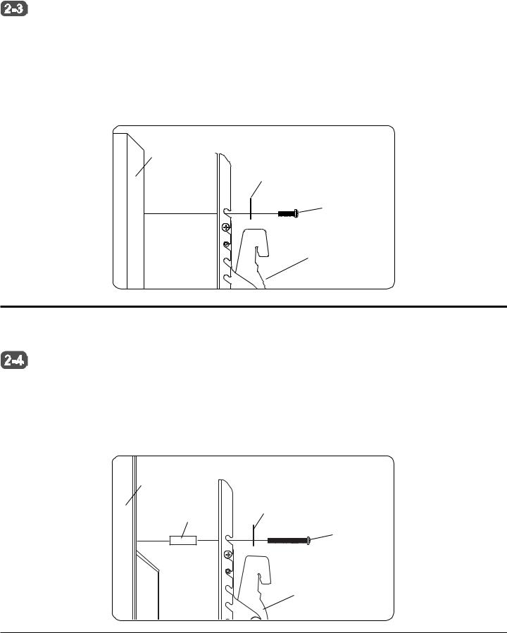
For Flat Back Screen


 Begin with the shortest length screw, hand thread through multi-washer and adapter bracket into screen as shown


 below. Screw must make at least three full turns into the mounting hole and fit snug into place. Do not over tighten. If screw cannot make three full turns into the screen, select a longer length screw from the baffled fastener pack. Repeat for remaining mounting holes, level brackets and tighten screws.
NOTE: Spacers may not be used, depending upon the type of screen.
If you have any questions, please call Peerless customer care at 1-800-729-0307 or visit our website at www.peerlessmounts.com/charts to locate your screen compatibility chart.
fig 2.3
SCREEN
MULTI-WASHER
SCREW
ADAPTER BRACKET (BB or CC)
For Bump-out or Recessed Back Screen


 Begin with longer length screw, hand thread through multi-washer, adapter bracket and spacer in that order into


 screen as shown below. Screw must make at least three full turns into the mounting hole and fit snug into place. Do not over tighten. If screw cannot make three full turns into the screen, select a longer length screw from the baffled fastener pack. Repeat for remaining mounting holes, level brackets and tighten screws.
If you have any questions, please call Peerless customer care at 1-800-729-0307 or visit our website at www.peerlessmounts.com/charts to locate your screen compatibility chart.
fig 2.4
SCREEN
SPACER |
MULTI-WASHER |
|
SCREW
ADAPTER BRACKET (BB or CC)
6 of 33 |
ISSUED: 09-20-06 SHEET #: 202-9167-3 01-26-07 |
With tape measure, measure the outside to outside of the brackets on the back of your screen. If width of the tilt brackets on back of the screen is over 18-1/2" shown in figure 3.1, using a 7/16" wrench, attach wing bracket (GG) to center bracket using two 1/4" serrated flanged locknuts (FF) as shown in figure 3.2. If width of the brackets on back of the screen is over 30-3/8", using a 7/16" wrench, attach second wing bracket (GG) to center bracket using two 1/4" serrated flanged locknut (FF) as shown in figure 3.3.
CAUTION: If mounting to two studs on 16" centers, and using the three plate configuration, A STUD MUST BE SKIPPED in the middle so distance between studs is 32".
AA
18.5"
GG
FF
AA
fig. 3.1 |
fig. 3.2 |
 AA
AA
GG
FF
fig. 3.3
7 of 33 |
ISSUED: 09-20-06 SHEET #: 202-9167-3 01-26-07 |
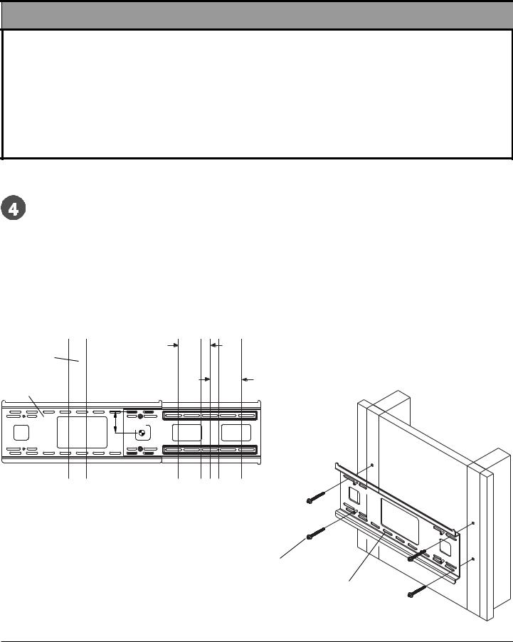
Installation to Double Wood Stud Wall
 WARNING
•Installer must verify that the supporting surface will safely support the combined load of the equipment and all attached hardware and components.
•Tighten wood screws so that wall plate is firmly attached, but do not overtighten. Overtightening can damage the screws, greatly reducing their holding power.
•Never tighten in excess of 80 in. • lb (9 N.M.).
•Make sure that mounting screws are anchored into the center of the stud. The use of an "edge to edge" stud finder is highly recommended.
•Hardware provided is for attachment of mount through standard thickness drywall or plaster into wood studs. Installers are responsible to provide hardware for other types of mounting situations.
NOTE: If mounting equipment weighing greater than 200 lbs, triple stud mounting is strongly recommended.
Skip to page 9
Wall plate (AA) can be mounted to two studs that are 16" apart. Use a stud finder to locate the edges of the studs.  Use of an edge-to-edge stud finder is highly recommended. Based on their edges, draw a vertical line down each
stud’s center. Place wall plate on wall as a template. The top mounting slots should be 2.5" above the desired screen center as shown in figure 4.1. Level plate, and mark the center of the four mounting holes. Make sure that the mounting holes are on the stud centerlines. Drill four 5/32" (4 mm) dia. holes 2-1/2" (65 mm) deep. Make sure that the wall plate is level, secure it using four #14 x 2.5" wood screws (DD) as shown in figure 4.2.
NOTE: Wall plate may be mounted up to 4" (102 mm) off center as shown in figure 4.1.
Skip to step 5.
|
4" |
|
STUD |
(102 mm) |
|
|
||
AA |
4" |
|
(102 mm) |
||
|
||
2.5" |
CS |
|
(64 mm) |
|
CS = center of screen |
fig. 4.1 |
DD
AA
fig. 4.2
8 of 33 |
ISSUED: 09-20-06 SHEET #: 202-9167-3 01-26-07 |
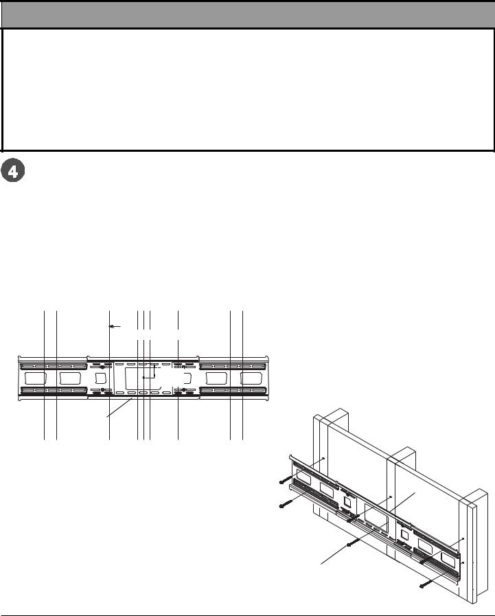
Installation to Triple Wood Stud Wall
 WARNING
•Installer must verify that the supporting surface will safely support the combined load of the equipment and all attached hardware and components.
•Tighten wood screws so that wall plate is firmly attached, but do not overtighten. Overtightening can damage the screws, greatly reducing their holding power.
•Never tighten in excess of 80 in. • lb (9 N.M.).
•Make sure that mounting screws are anchored into the center of the stud. The use of an "edge to edge" stud finder is highly recommended.
•Hardware provided is for attachment of mount through standard thickness drywall or plaster into wood studs. Installers are responsible to provide hardware for other types of mounting situations.
Wall plate (AA) can be mounted to three studs that are 16" apart. Use a stud finder to locate the edges of the studs.  Use of an edge-to-edge stud finder is highly recommended. Based on their edges, draw a vertical line down each
stud’s center. Place wall plate on wall as a template. The top mounting slots should be 2.5" above the desired screen center as shown in figure 4.3. Level plate, and mark the center of the six mounting holes. Make sure that the mounting holes are on the stud centerlines. Drill six 5/32" (4 mm) dia. holes 2-1/2" (65 mm) deep. Make sure that the wall plate is level, secure it using six #14 x 2.5" wood screws (DD) as shown in figure 4.4.
NOTE: When mounting equipment weighing greater than 200 lbs, triple stud mounting is strongly recommended. If mounting to two studs on 16" centers, leave an open stud in center. Wall plate may be mounted up to 4" (102 mm) off-center as shown in figure 4.3.
Skip to step 5.
STUD
4" 
 4"
4" 
(102 mm) (102 mm)
CS |
2.5" |
|
(64 mm) |
||
|
AA
CS = center of screen |
fig. 4.3 |
AA
DD
fig. 4.4
9 of 33 |
ISSUED: 09-20-06 SHEET #: 202-9167-3 01-26-07 |

Installation to Solid Concrete or Cinder Block
 WARNING
•When installing Peerless wall mounts on cinder block, verify that you have a minimum of 1-3/8" of actual concrete thickness in the hole to be used for the concrete anchors. Do not drill into mortar joints! Be sure to mount in a solid part of the block, generally 1" minimum from the side of the block. Cinder block must meet ASTM C-90 specifications. It is suggested that a standard electric drill on slow setting is used to drill the hole instead of a hammer drill to avoid breaking out the back of the hole when entering a void or cavity.
•Concrete must be 2000 psi density minimum. Lighter density concrete may not hold concrete anchor.
•Make sure that the supporting surface will safely support the combined load of the equipment and all attached hardware and components.
Make sure that wall plate (AA) is level, use it as a  template to mark four mounting holes. The top
mounting hole should be 2.5" above the desired screen center as shown in figure 4.1 on page 8. Drill four 1/4" (6 mm) dia. holes to a minimum depth of 2.5" (64 mm). Insert anchors (EE) in holes flush with wall as shown (right). Place wall plate over anchors and secure with #14 x 2.5" screws (DD). Level, then tighten all fasteners.
1 |
concrete |
|
|
|
surface |
EE
Drill holes and insert anchors (EE).
NOTE: Six holes and six sets of fasteners are required when mounting the wall plate for equipment weighing greater than 200 lbs.
 WARNING
•Tighten screws so that wall plate is firmly attached, but do not overtighten. Overtightening can damage screws, greatly reducing their holding power.
•Never tighten in excess of 80 in. • lb (9 N.M.).
2 |
AA |
|
|
|
DD EE |
Place plate (AA) over anchors (EE) and secure with screws (DD).
3
 WARNING
•Always attach concrete anchors directly to loadbearing concrete.
Tighten all fasteners.
•Never attach concrete anchors to concrete covered with plaster, drywall, or other finishing material. If mounting to concrete surfaces covered with a finishing surface is unavoidable, the finishing surface must be counterbored as shown below. Be sure concrete
anchors do not pull away from concrete when tighten- |
AA |
|
ing screws. If plaster/drywall is thicker than 5/8", |
||
|
||
custom fasteners must be supplied by installer. |
DD |
|
(Not evaluated by UL) |
||
|
|
INCORRECT |
|
|
CORRECT |
VIEW |
wall |
concrete |
wall plate |
concrete |
plate |
|
|
|
|
|
|
|
|
|
CUTAWAY |
plaster/ |
|
|
plaster/ |
dry wall |
|
|
drywall |
|
|
|
|
|
|
|
|
|
|
10 of 33 |
solid |
concrete |
|
|
|
|
|
|
|
EE |
cinder |
block |
|
|
|
ISSUED: 09-20-06 SHEET #: 202-9167-3 01-26-07
 Loading...