


DPC 1400X
OWNER’S MANUAL
DPC®1400X
2 x 700 Watt Professional Stereo Power Amplifier
®
2
Intended to alert the user to the presence of uninsulated “dangerous voltage” within the product’s
enclosure that may be of sufficient magnitude to constitute a risk of electric shock to persons.
Intended to alert the user of the presence of important operating and maintenance (servicing)
instructions in the literature accompanying the product.
CAUTION: Risk of electrical shock — DO NOT OPEN!
CAUTION: To reduce the risk of electric shock, do not remove cover. No user serviceable parts inside. Refer
servicing to qualified service personnel.
WARNING: To prevent electrical shock or fire hazard, do not expose this appliance to rain or moisture. Before
using this appliance, read the operating guide for further warnings.
Este símbolo tiene el propósito, de alertar al usuario de la presencia de “(voltaje) peligroso” que no tiene
aislamiento dentro de la caja del producto que puede tener una magnitud suficiente como para constituir
riesgo de corrientazo.
Este símbolo tiene el propósito de alertar al usario de la presencia de instruccones importantes sobre la
operación y mantenimiento en la literatura que viene con el producto.
PRECAUCION: Riesgo de corrientazo — No abra.
PRECAUCION: Para disminuír el riesgo de corrientazo, no abra la cubierta. No hay piezas adentro que el usario
pueda reparar. Deje todo mantenimiento a los técnicos calificados.
ADVERTENCIA: Para evitar corrientazos o peligro de incendio, no deje expuesto a la lluvia o humedad este
aparato Antes de usar este aparato, Iea más advertencias en la guía de operación.
Ce symbole est utilisé pur indiquer à l’utilisateur la présence à l’intérieur de ce produit de tension nonisolée dangereuse pouvant être d’intensité suffisante pour constituer un risque de choc électrique.
Ce symbole est utilisé pour indiquer à l’utilisateur qu’il ou qu’elle trouvera d’importantes instructions sur
l’utilisation et l’entretien (service) de l’appareil dans la littérature accompagnant le produit.
ATTENTION: Risques de choc électrique — NE PAS OUVRIR!
ATTENTION: Afin de réduire le risque de choc électrique, ne pas enlever le couvercle. Il ne se trouve à l’intérieur
aucune pièce pouvant être reparée par l’utilisateur. Confier I’entretien à un personnel qualifié.
AVERTISSEMENT: Afin de prévenir les risques de décharge électrique ou de feu, n’exposez pas cet appareil à la
pluie ou à l’humidité. Avant d’utiliser cet appareil, lisez les avertissements supplémentaires situés dans le guide.
Dieses Symbol soll den Anwender vor unisolierten gefährlichen Spannungen innerhalb des Gehäuses
warnen, die von Ausreichender Stärke sind, um einen elektrischen Schlag verursachen zu können.
Dieses Symbol soll den Benutzer auf wichtige Instruktionen in der Bedienungsanleitung aufmerksam
machen, die Handhabung und Wartung des Produkts betreffen.
VORSICHT: Risiko — Elektrischer Schlag! Nicht öffnen!
VORSICHT: Um das Risiko eines elektrischen Schlages zu vermeiden, nicht die Abdeckung enfernen. Es befinden
sich keine Teile darin, die vom Anwender repariert werden könnten. Reparaturen nur von qualifiziertem
Fachpersonal durchführen lassen.
ACHTUNG: Um einen elektrischen Schlag oder Feuergefahr zu vermeiden, sollte dieses Gerät nicht dem Regen
oder Feuchtigkeit ausgesetzt werden. Vor Inbetriebnahme unbedingt die Bedienungsanleitung lesen.
DPC® 1400X
Thank you for purchasing the DPC
®
1400X! The DPC®1400X represents years of digital power
amplifier research packed into a one rack space power-house. Delivering 1,400 watts into
4 ohms bridged, or 2 x 700 watts into 2 ohms in stereo, the DPC 1400X reaches new output
heights.
With all connections on the back panel and all the controls on the front panel, the DPC 1400X
is certain to make life a lot easier for the installers and in live performance applications. You’ll
also find Peavey’s patented DDT
™
compression circuitry and combo connector inputs two really
convenient and useful extras.
Please read all of this before using the DPC 1400X as it contains important precautions and safety
information.
FRONT P
ANEL FEATURES
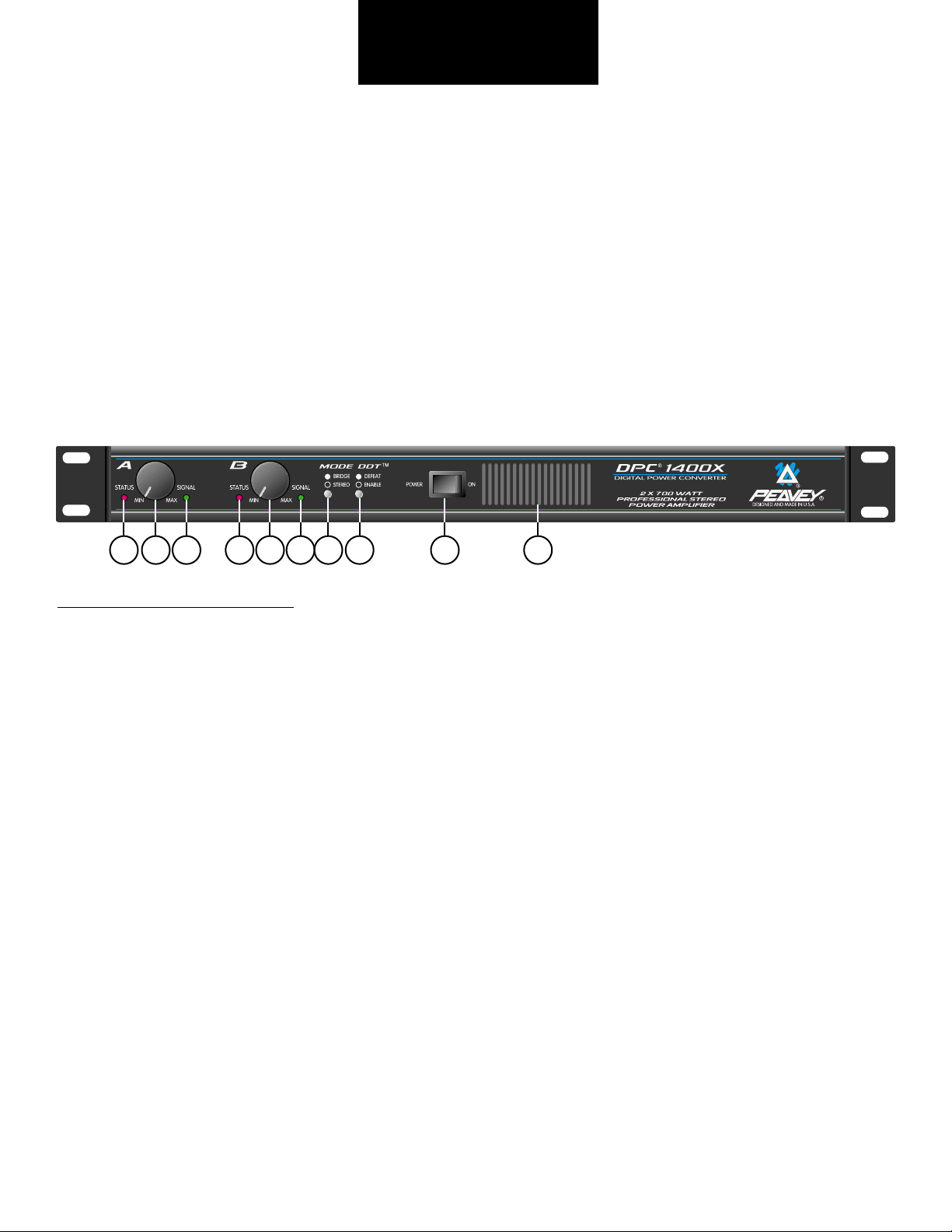
STATUS LEDs (1)
Bi-colored LED used to indicate the status of the channel. Channels A and B have separate Status
LEDs to monitor channel conditions. If both LEDs are not lit at power-up, follow the procedure to
check if the fuse needs replacing. If only one channel’s Status LED is lit check to see it the amp
is in bridge mode (4). If the LED is green, this indicates a normal operation. If the LED is red, then
the amplifier is overheated and will shut down for approximately 5 minutes or until cool enough to
operate safely. If the LED pulsates red, this indicates that there is a problem with the amplifier and it
should be serviced by a qualified technician.
INPUT SENSITIVITY (2)
These controls are used to adjust the input gain of each channel. Maximum gain is achieved with
the control turned fully clockwise. In this position the user will achieve maximum system headroom.
If set lower than full clockwise, lower system noise will occur at the expense of headroom.
SIGNAL LED (3)
Bi-colored LED used to indicate the signal status of a channel. If the LED is not lit, this indicates
no signal at the input. This could be caused by bad cables or the Input Sensitivity (2) being set to
zero. If this LED is green, then a signal is present at the input. If the LED is red, this indicates that
DDT compression is occurring. When DDT compression is disabled a red LED indicates signal clipping.
ENGLISH
1 2 3
1
2 3 4 5 6 7
3
MODE SWITCH (4)
This switch is used to change operational modes of the amplifier. When the switch is pressed in,
the unit is placed in bridge mode (bridge mode is explained later in this manual) and uses only the
Channel A input. When the switch is out, the amplifier operates in stereo mode utilizing both inputs.
Accidental selection of bridge mode from stereo mode while the unit is in operation could cause
severe damage to loudspeakers, particularly biamped systems.
DDT SWITCH (5)
This switch is used to enable or defeat the internal DDT
™
compression circuitry. Normally the DDT
function should be enabled to minimize the possibility of either or both channels going into clipping
or overload. With DDT defeated, a severe overload could cause the mains fuse to blow as a matter
of course. (DDT is covered in greater detail later in this manual.)
POWER SWITCH (6)
This switch is used to apply power to the unit, thus turning the unit on. Use the status indicators (1)
to verify the actual power condition of the amp.
COOLING VENTS (7)
These vents provide a path for airflow. Since the DPC 1400X is a fan cooled device, it is very
important not to cover these vents or obstruct the flow of air in any way.
BACK
PANEL FEA
TURES
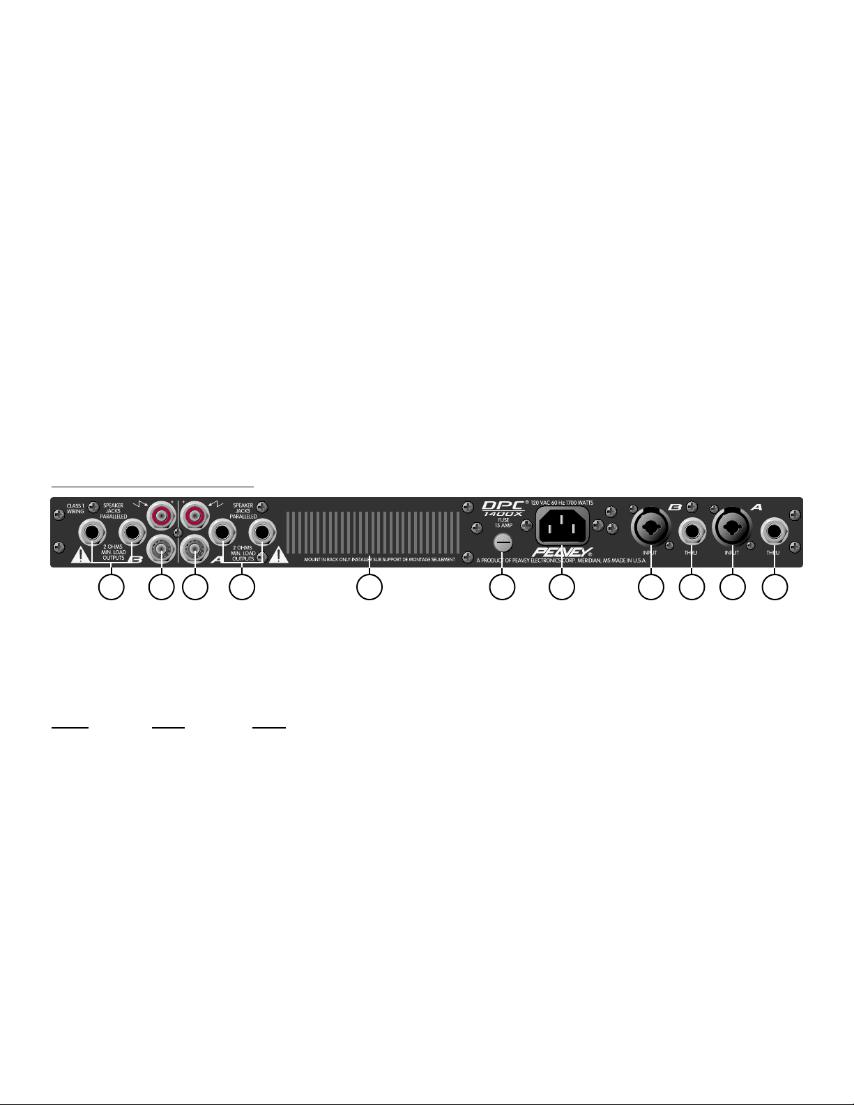
CHANNEL INPUT (8)
This input features a combo connector that will accept a standard three-pin male XLR, 1/4" TRS
(Tip-Ring-Sleeve), or 1/4" mono plug. An electronically balanced input is available via XLR and
1/4" TRS use. The unit is internally wired for the following:
Input
XLR TRS
(+) Pin 2 Tip
(-) Pin 3 Ring
GND Pin 1 Sleeve
Unbalanced input is achieved by use of a 1/4" mono plug (patch cable). It is best to keep the
cable from the output device to the input of the DPC 1400X as short as possible during unbalanced
operation.
INPUT THRU (9)
This TRS 1/4" jack is used to daisy chain the inputs of the DPC 1400X to the inputs of other power
amps or devices. Once again, short patch cables are highly recommended to minimize hum.
BINDING POST SPEAKER OUTPUTS (10)
Because of their high current handling capabilities, the binding post is recommended over the
standard 1/4" connector. For this reason, one set of binding posts is provided for each channel of the the
10 10 7 12 13 8 9 9811 11
4

DPC 1400X. The binding posts of each channel are wired in parallel with that channel’s 1/4"
outputs. This allows for parallel speaker systems. The minimum impedance in stereo mode is 2
ohms. Use of the amplifier below the minimum 2 ohm rating could result in overheating and thermal
shutdown. In bridge mode connect the banana plug of your speaker cable to the red binding posts
of channels A and B. The red binding post of channel A is the positive output terminal and the
minimum load impedance is increased to 4 ohms while in bridge mode. (Bridge mode is explained
in more detail later in this manual.)
PARALLEL 1/4" SPEAKER OUTPUTS (11)
Two parallel 1/4" speaker output jacks are provided for each channel of the DPC 1400X.
When adding speakers in parallel always keep in mind your total speaker impedance,
insuring that it does not drop below the minimum load impedance rating of the DPC 1400X.
FUSE (12)
The fuse is located in the cap of the fuse holder. If the fuse should fail, IT MUST BE
REPLACED WITH THE SAME TYPE AND VALUE IN ORDER TO AVOID DAMAGE TO TO
EQUIPMENT AND TO PREVENT VOIDING THE WARRANTY. If the amp repeatedly blows
fuses, it should be taken to a qualified service center for repair.
WARNING: THE FUSE SHOULD ONLY BE REPLACED WHEN THE POWER CORD HAS
BEEN DISCONNECTED FROM ITS POWER SOURCE.
AC LINE CORD SOCKET (13)
Provided to accept the removable (IEC) type AC line cord. Connect only to proper source (see back
panel markings.)
INSTALLATION AND CONNECTION
The DPC professional series of power amplifiers is designed for durability in commercial installations
and has the quality of performance required in studio. These units are a standard rack-mount configuration height, and each is cooled by a variable-speed internal fan. All input and output connections
are on the back panel. Additionally, the level controls and selector switches are on the front panel.
The front panel also contains LED indicators for power and DDT activation, and the mains power
switch.
INDUSTRIAL AND COMMERCIAL INSTALLATIONS
For commercial and other installations where sustained high power operation is required, the
amplifiers should be mounted in a standard 19" rack. It is not necessary to leave a rack space
between each amplifier in the stack since each fan pulls air in from the rear and exhausts the hot air
out the front. However, an adequate cool air supply must be provided for the amplifier when rackmounted. The internal fan must have a source of air that is not preheated by other equipment. If
cool, the amplifier will start up in low speed fan operation and will normally stay at low speed
operation unless sustained high power operating levels occur. Then, as the amplifier heat sinks heat
up, the automatic thermal sensing circuitry will increase the fan speed. Depending upon signal
conditions and amp loading, the fan speed may increase to a maximum value, or it may decrease to
a minimum value. This situation is quite normal. If cooling is inadequate due to preheated air or a
reduction of air flow occurs due to blockage of the amplifier inlet/outlet ports, or if the amplifier is
severely overloaded or short circuited, the amplifier thermal sensing system may cause temporary
shutdown of the unit. This is indicated by the status LEDs on the front panel illuminating red.
Depending upon the available cooling air, operation should be restored relatively quickly, and the
5

status LEDs will be illuminated green. In any event, corrective action should be taken to determine
the cause of the thermal shutdown. If the amplifier is not severely overloaded or shorted and air flow
is normal in and out of the amplifier, then steps should be taken to provide a cooler environment for
all the amplifiers. As a general rule, the cooler electronic equipment is operated, the longer its useful
service life.
STUDIO AND FACILITY INSTALLATION
In most low to medium power applications, the power amplifier can be mounted in any configuration.
It is desirable that, if at all possible, the power amplifier be located at the top of an equipment stack.
This will prevent possible overheating of sensitive equipment by the hot air rising from the power
amplifier. As a general rule, most studio requirements will never cause high speed fan operation.
However, if they do, this may indicate that you have not taken the necessary steps to provide
adequate cooling. Remember, closed up in a cabinet, a DPC Series power amplifier will have severe
cooling problems, even at low power levels. Again, inadvertent short circuit or sustained overload
usage could also cause temporary thermal shutdown and/or blowing of the fuse. Also, most home
wiring and electrical circuits are only 15 amps.
BRIDGE MODE
The bridge mode on stereo amplifiers is often misunderstood as to the actual operation and usage.
In basic terms, when a two-channel amplifier is operated in the bridge mode, it is converted into a
single-channel unit with a power rating equal to the sum of both channels’ power ratings at a Load
Rating of twice that of the single channel rating. For example, the DPC 1400X is rated at 700 watts
RMS per channel into 2 ohms. The bridge ratings are 1,400 watts RMS into 4 ohms (minimum load).
Bridge mode operation is accomplished by placing the mode switch in the “BRIDGE” position,
connecting the positive speaker lead to Channel A red binding post, negative speaker lead to
Channel B red binding post, and using Channel A as the input channel. All Channel B input functions
are defeated, and they serve no purpose now. Another common use for the bridge mode is in
subwoofer applications where very high power levels are required to reproduce extreme low
frequencies. Such enclosures usually contain 2 or 4 loudspeakers to handle the power levels
involved. For bridge mode usage, the enclosure impedance must be 4 or 8 ohms—never below
4 ohms!
DDT
™
Peavey’s patented DDT (Distortion Detection Technique) compression circuit enables the user to
maximize the performance of the amplifier/speaker combination by preventing the power amp from
running out of headroom (clipping). This compression system is activated by a very unique circuit
that senses signal conditions which might overload the amplifier and activates compression (reduces
the amp gain) when clipping is imminent. Threshold of compression, then, is clipping itself, and no
specific threshold control is used. This technique effectively utilizes every precious watt available for
the power amplifier to reproduce the signal, while at the same time minimizing clipping and distortion
and thus significantly reducing the potential of loudspeaker degradation and damage. The DDT
system is an automatic hands-off approach to the problem of power amplifier clipping. Since the
DPC Series power amplifiers use a fuse for “over current” protection, the DDT compression system
plays even a more important role in continuous performance by preventing each channel from
clipping and overload. Continuous operation at clipping can cause the fuse to blow, but with the DDT
activated, this problem is minimized. For this reason, you should always have the DDT compression
system enabled.
6

Output Power: (typical value, 120 V AC, 60 Hz):
Stereo mode, both channels driven
2 ohms, 1,000 W power channel peak music power
4 ohms, 700 W power channel peak music power
8 ohms, 500 W power channel peak music power
Bridge mode
4 ohms, 2,000 W power peak music power
8 ohms, 1,400 W power peak music power
Rated Output Power (120 V AC, 60 Hz):
Stereo mode, both channels driven
2 ohms, 1 kHz, 700 W RMS per channel
4 ohms, 1 kHz, 525 W RMS per channel
8 ohms, 1 kHz, 325 W RMS per channel
Bridge mode
4 ohms, 1 kHz, 1,400 W RMS
8 ohms, 1 kHz, 1,000 W RMS
Power Bandwidth:
Stereo mode, both channels driven
4 ohms, 10 Hz to 20 kHz
Total Harmonic Distortion:
Stereo mode, both channels driven
1 kHz, 4 ohms rated output, less than 0.1%
Hum and Noise:
Stereo mode, both channels driven
Below rated output power 4 ohms, greater than
95 dB (A-weighted)
Damping Factor:
Stereo mode, both channels driven
4 ohms, 100 Hz, greater than 500
Input Sensitivity:
Input attenuator set @ FCW @ rated output power,
4 ohms, 1.4 V RMS (+3 dBV)
Input Impedance:
10k ohms unbalanced
Channel Voltage Gain:
Input attenuator set @ FCW
Stereo mode, 4 ohms, 1 kHz, 30 dB
Bridge mode, 8 ohms, 1 kHz, 39 dB
Frequency Response:
Stereo mode, both channels driven
+0.5, -3 dB, 1 W RMS, 4 ohms, 3 Hz to 25 kHz
The frequency response is internally controlled to
optimize phase linearity and improve transient
response.
Slew Rate:
The slew rate is internally controlled by a Bessel
filter to optimize phase linearity and improve
transient response. Because of this circuitry,
the amplifier cannot slew rate limit.
Power Consumption:
Stereo mode, both channels driven @ rated output
power, 4 ohms 10 A @ 120 V AC
Cooling System:
Continuously variable speed DC blower
DDT™Compression System:
Automatic, switchable with LED indicator
Dimensions and Height:
• Height 1.75" (4.4 cm)
• Width 19" (48.3 cm)
• Depth 16.5" (41.9 cm)
• Weight 15 lbs. (6.8 kg)
Specifications subject to change without notice.
DPC®1400X SPECIFICATIONS
7
8
In
Out
215FX
™
EQ
Monitor Input
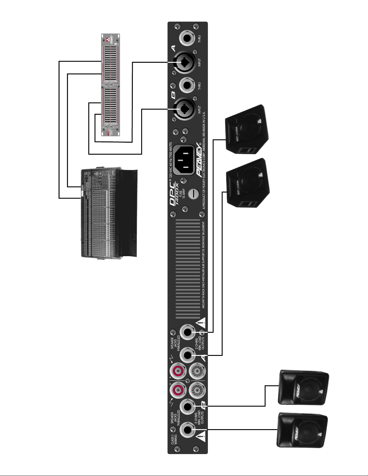
1400X Hookup Diagram
®
DPC
Main
Monitor
4034
™
SRC
Main Input
112M
™
SP
Monitor Output
200
™
Main
Output
Impulse

DPC® 1400X
Nous vous félicitons pour l’achat de ce DPC® 1400X! Le DPC®1400X renferme des années de
recherche dans le domaine les amplificateurs numériques dans une unité rack. Avec ses 1400 Watt
sous 4 Ohm en mode bridge ou 2 x 700 Watt sous 2 Ohm en stéréo, le DPC 1400X atteind de nouveaux sommets de puissance.
Toutes les connections sont situées à l’arrière et tous les contrôles sont en façade, de manière à
simplifier au maximum son installation et son utilisation en situation Live. Le DPC 1400X est en plus
équipé de la compression DDT
™
brevetée par Peavey et d’entrées de type combo.
Lisez attentivement ce manuel afin d’utiliser correctement votre DPC 1400X correctement et de
respectez les mesures de sécurité nécessaires.
Veuillez-vous référer au <front panel> art situé dans la
section en langue anglaise de ce manuel.
F
ACE AV
ANT
LEDS DE STATUT (1)
LEDs bicolores indiquant le statut du canal. Les canaux A et B possèdent chacun leur LED de
statut. Si les deux LEDs restent éteintes à la mise sous tension, suivez la procédure de remplacement des fusibles. Si seule une est allumée, vérifiez que l’amplificateur est en mode bridge (4). Une
LED verte indique une opération normale. Une LED rouge indique que l’amplificateur a surchauffé et
qu’il ne pourra être mis en route avant 5 minutes ou avant qu’il n’atteigne une température suffisament basse. Une LED clignotant en rouge signal qu’il y a un problème avec l’amplificateur et qu’il
doit être réparé par un technicien qualifié.
SENSIBILITES D’ENTREES (2)
Ces boutons de réglage permettent d’ajuster le gain d’entrée pour chaque canal, c’est-à-dire de
déterminer le volume sonore délivré par l’amplificateur de puissance pour un signal d’entrée donné.
Le gain d’entrée maximum (niveau de sensibilité minimale) est obtenu lorsque le bouton est tourné
à fond dans le sens horaire; cette position assure une dynamique maximale au système. Un réglage
inférieur permettra une réduction du niveau de bruit mais aura pour conséquence une réduction de
la dynamique du système.
LEDS SIGNAL (3)
LED bicolore indiquant le statut du canal. Si elle reste éteinte, aucun signal n’est présent en entrée.
Cela peut provenir de connexions défectueuses ou d’un réglage à zéro de la sensibilité d’entrée (4).
Si la LED est de couleur verte, un signal est présent en entrée. Le voyant s’illumine en rouge
lorsque la compression DDT entre en fonction sur le canal. Lorsque le commutateur (5) désactive la
compression DDT, la couleur rouge indique l’écrêtage du signal.
SELECTEUR DE MODE (4)
Ce commutateur permet de sélectionner le mode de fonctionnement stéréo ou bridge. En mode normal, l’amplificateur travaille en stéréo et les deux canaux d’entrée sont utilisés. Lorsqu’il est engagé,
l’amplificateur est en mode bridge et n’utilise que le canal d’entrée A. Il convient de faire preuve de
FRANÇAIS
9
 Loading...