


CA - A540B™/CA - A800B™
Cinema Power Amplifiers
Operating Guide

 ®
®
Intended to alert the user to the presence of uninsulated “dangerous voltage” within the product’s enclosure that may be of sufficient magnitude to constitute a risk of electric shock to persons.
Intended to alert the user of the presence of important operating and maintenance (servicing) instructions in the literature accompanying the product.
CAUTION: Risk of electrical shock — DO NOT OPEN!
CAUTION: To reduce the risk of electric shock, do not remove cover. No user serviceable parts inside. Refer servicing to qualified service personnel.
WARNING: To prevent electrical shock or fire hazard, do not expose this appliance to rain or moisture. Before using this appliance, read the operating guide for further warnings.
Este símbolo tiene el propósito, de alertar al usuario de la presencia de “(voltaje) peligroso” sin aislamiento dentro de la caja del producto y que puede tener una magnitud suficiente como para constituir riesgo de descarga eléctrica.
Este símbolo tiene el propósito de alertar al usario de la presencia de instruccones importantes sobre la operación y mantenimiento en la información que viene con el producto.
PRECAUCION: Riesgo de descarga eléctrica ¡NO ABRIR!
PRECAUCION: Para disminuír el riesgo de descarga eléctrica, no abra la cubierta. No hay piezas útiles dentro. Deje todo mantenimiento en manos del personal técnico cualificado.
ADVERTENCIA: Para evitar descargas eléctricas o peligro de incendio, no deje expuesto a la lluvia o humedad este aparato Antes de usar este aparato, Iea más advertencias en la guía de operación.
Ce symbole est utilisé dans ce manuel pour indiquer à l’utilisateur la présence d’une tension dangereuse pouvant être d’amplitude suffisante pour constituer un risque de choc électrique.
Ce symbole est utilisé dans ce manuel pour indiquer à l’utilisateur qu’il ou qu’elle trouvera d’importantes instructions concernant l’utilisation et l’entretien de l’appareil dans le paragraphe signalé.
ATTENTION: Risques de choc électrique — NE PAS OUVRIR!
ATTENTION: Afin de réduire le risque de choc électrique, ne pas enlever le couvercle. Il ne se trouve à l’intérieur aucune pièce pouvant être reparée par l’utilisateur. Confiez I’entretien et la réparation de l’appareil à un réparateur Peavey agréé.
AVERTISSEMENT: Afin de prévenir les risques de décharge électrique ou de feu, n’exposez pas cet appareil à la pluie ou à l’humidité. Avant d’utiliser cet appareil, lisez attentivement les avertissements supplémentaires de ce manuel.
Dieses Symbol soll den Anwender vor unisolierten gefährlichen Spannungen innerhalb des Gehäuses warnen, die von Ausreichender Stärke sind, um einen elektrischen Schlag verursachen zu können.
Dieses Symbol soll den Benutzer auf wichtige Instruktionen in der Bedienungsanleitung aufmerksam machen, die Handhabung und Wartung des Produkts betreffen.
VORSICHT: Risiko — Elektrischer Schlag! Nicht öffnen!
VORSICHT: Um das Risiko eines elektrischen Schlages zu vermeiden, nicht die Abdeckung enfernen. Es befinden sich keine Teile darin, die vom Anwender repariert werden könnten. Reparaturen nur von qualifiziertem Fachpersonal durchführen lassen.
ACHTUNG: Um einen elektrischen Schlag oder Feuergefahr zu vermeiden, sollte dieses Gerät nicht dem Regen oder Feuchtigkeit ausgesetzt werden. Vor Inbetriebnahme unbedingt die Bedienungsanleitung lesen.
2

ENGLISH
CA-A540B™ and CA-A800B™
Common Features
•SPS™ compression with LED indicators and defeat switch
•Slew Rate: 20 V/microsecond, stereo mode
•Frequency Response (each channel): 20 Hz to 20 kHz, ±0.2 dB, at rated power
•Total Harmonic Distortion: Less than 0.07%, at rated power
•Hum and Noise: 100 dB below rated power, unweighted
Congratulations! You are now the owner of a Peavey CinemAcoustics™ amplifier designed especially for the theater marketplace. The Peavey CinemAcoustics amplifiers, models CA-A540B™ and CAA800B™, are the result of the latest developments in technology, allowing Peavey to provide you with cost-effective amplifiers that do not sacrifice performance or reliability, while still continuing to meet the demanding needs of today’s digital theater.
In the development of the CinemAcoustics CA-A540B and CA-A800B amplifiers, Peavey’s engineers left no stone unturned. Right up front at the power source, CinemAcoustics’ amplifiers utilize massive power transformers, which are based on a new approach to power transformer design, optimizing both cost and performance. On the power delivery side, these amplifiers utilize the latest in semiconductor power device technology and implement a unique, two-speed fan-cooled heat sink arrangement, insuring quality and ruggedness. The features and performance found in these amplifiers place them in a class of their own — the CinemAcoustics line!
Each amplifier is attractively packaged with rugged rack-mountable construction. The front panel of each amplifier contains a rocker mains power switch, an LED power indicator, and dual LED SPS activation indicators. The back panel of each amplifier has a resetable circuit breaker, an input level control, a Euro input connector, and an output barrier strip. Additionally, the back panel contains switches for stereo/bridge select and SPS defeat.
This operating guide is intended to serve both the CA-A540B and CA-A800B CinemAcoustics series power amplifiers. Although each has different power ratings, the overall packaging and features are similar.
3
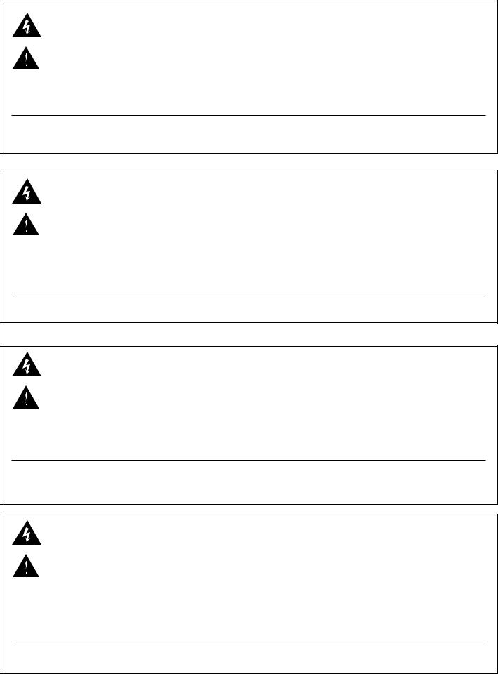
FRONT PANEL CA-A800B
1 |
2 |
1 |
POWER
Cinem coustics
CA - A800B
SPS ACTIVE A |
POWER ON |
SPS ACTIVE B |
CINEMA POWER AMPLIFIER
(1) SPS COMPRESSION ACTIVE LED
These indicators, one per channel, illuminate when SPS compression is taking place. This LED becomes a CLIP indicator when the rear panel SPS ENABLE/DEFEAT switch is in the DEFEAT position.
(2) POWER LED
This indicator illuminates when AC mains power is applied to the amplifier and both channels are operational. The power LED will go dark if AC mains power is disconnected, if either channel experiences a fault condition, or if the amplifier exceeds the safe operating temperature limits.
(3) MAINS POWER SWITCH
The mains power switch is a heavy-duty, rocker-type switch. Selecting the “O” position turns the power amplifier off. Selecting the “I” position turns the power amplifier on.
4
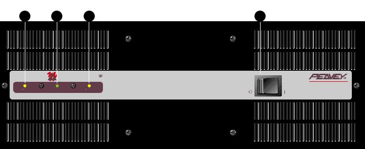
BACK PANEL CA-A800B |
|
|
|
|
6 |
7 |
|
|
|
BUILT UNDER U.S. PATENT NO. 4,318,053 |
|
coustics |
||
OUTPUT B |
OUTPUT A |
|
||
+ |
+ |
CINEMA POWER AMPLIFIER |
||
|
|
|||
|
|
|
10 |
|
400W/8 OHMS 56.6V RMS PER CHANNEL |
dBV INPUT SENSITIVITY |
dBV INPUT SENSITIVITY |
ENABLE |
|
700W/4 OHMS 52.9V RMS PER CHANNEL |
|
|||
5 |
2 OHM MINIMUM LOAD |
CLASS 2 WIRING |
|
RESET |
MOUNT IN RACK ONLY.
INSTALLER SUR SUPPORT DE MONTAGE SEULEMENT
120 VAC
60 Hz
1500 WATTS
|
11 |
|
|
|
|
|
|
|
8 |
||||||||
|
|
|
|
|
|
|
|
|
|
|
|
|
|
|
|
|
|
+21 |
+6 |
|
|
|
|
|
|
|
|
|
|
|
|
|
+21 |
+6 |
|
|
|
|
|
|
|
|
|
|
|
|
|
|
|
|
|
|
9 |
|
|
|
|
|
|
|
|
|
|
|
|
|
|
|
|
|
|
|
+3 |
|
|
|
|
|
|
|
|
|
|
+3 |
MODE |
||||
|
- + |
+ - |
|
|
|
|
|
|
STEREO |
||||||||
|
|
|
|
|
|
|
|
|
|
|
|
|
|
|
|
|
|
|
|
|
|
|
|
|
|
|
|
|
|
|
|
|
|
|
BRIDGE |
|
|
|
|
|
|
|
|
|
|
|
|
|
|
|
|
|
|
|
|
|
|
|
|
|
|||||||||||
|
|
|
|
CA - A800B |
|
||||||||||||
|
A DIVISION OF PEAVEY ELECTRONICS CORP |
|
|||||||||||||||
|
MERIDIAN, MS. |
MADE IN U.S.A. |
|
||||||||||||||
4
(4) MAINS POWER SOURCE
All CinemAcoustics Series power amplifiers are fitted with a single, heavy-duty, three-conductor line cord and a conventional, three-terminal AC plug with a ground pin for 120 V products. For 100 V and 220 V products, the line cord is fitted with the appropriate power connector. The power plug should be connected to an independent circuit capable of supporting at least 15 amps for 100 V and 120 V service, and 7.5 amps for 220 V service. This is particularly important for applications where the amplifiers will be continuously operated at, or near, their maximum power rating. The use of extension cords should be avoided, but when necessary, use a three-wire type with at least a 14 WG wire size.
Always allow a qualified electrician to install any new electrical service. The ground pin of the  power plug is provided for your safety and should not be defeated. To prevent the risk of shock
or fire hazard, always be sure that the amplifier is properly grounded.
NOTE: FOR UK ONLY
As the colors of the wires in the mains lead of this apparatus may not correspond with the colored markings identifying the terminals in your plug, proceed as follows: (1) The wire which is colored green and yellow must be connected to the terminal which is marked by the letter E, or by the earth symbol, or colored green or green and yellow. (2) The wire which is colored blue must be connected to the terminal which is marked with the letter N, or the color black. (3) The wire which is colored brown must be connected to the terminal which is marked with the letter L or the color red.
(5) CIRCUIT BREAKER
The power circuit breaker serves to protect the amplifier. The trip current value has been carefully chosen to allow continuous operation at the rated power while still offering adequate
protection. Under normal conditions, the breaker will not trip unless there is a fault condition that draws excessive mains current. Please note, however, that abnormal conditions such as a short circuit applied to an output or continuous operation at overload or clipping will also cause the breaker to trip. If you suspect that the breaker has tripped because of abnormal conditions, be sure to remedy the cause of the fault before resetting the breaker. When tripped, the breaker button extends outward nearly 1/2", and can be reset by pushing inward after a brief wait to allow the breaker to cool down. When not tripped, the breaker button extends outward about 1/4". If the
5

breaker trips instantly each time you attempt to reset it, the unit should be taken to a qualified service center for repair.
(6) OUTPUT MONITOR
This standard Quick-Connect™ RJ11 modular connector provides Channel A and B signals to Peavey’s booth monitor products such as the CA-M400. Refer to the diagram above the connector for proper polarity. (+ is equal to the channel’s positive output.) The channels are indicated below the connector.
(7) BARRIER STRIP SPEAKER OUTPUTS
The SPEAKER OUTPUTS for each channel are provided by means of a heavy-duty, four screw barrier strip. The screw terminals marked “+” are the power amplifier outputs for each channel.
The remaining screw terminals are ground (chassis). The minimum recommended speaker load impedance is 4 ohms per channel, or 8 ohms in BRIDGE mode. Operation into loads below the recommended load impedance can result in temporary amplifier shutdown due to internal fault sensing.
(8) SPS SWITCH
This switch is used to either ENABLE or DEFEAT the SPS safety compressor. Normally, the SPS switch should be in the ENABLE position to minimize the possibility of a channel going into clipping or overload. With SPS defeated, a severe overload could cause the unit’s circuit breaker to trip.
(9) MODE SWITCH
This switch is used to select either STEREO or BRIDGE mode for the amplifier operation. Care should be exercised whenever the BRIDGE mode is selected. Accidental selection of this mode could cause damage to loudspeakers, particularly in BIAMPED systems. NOTE: Peavey does not recommend the use of BRIDGE mode for normal theater applications.
(10) INPUT LEVEL
The INPUT controls are labeled in approximately 3 dB increments for ease of gain adjustment. Maximum input gain is achieved at the full clockwise setting. When used with CinemAcoustics signal processors, these controls should be left in the full clockwise position.
6
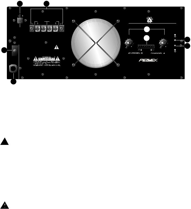
(11) EURO CONNECTOR INPUTS
The popular plugable Euro connector is provided for the inputs for each channel. These inputs are balanced electronically, with the terminals marked “+” as the positive amplifier inputs, and the
terminals marked “-” as the negative amplifier inputs. The remaining terminals are ground (chassis). If possible, always use two-conductor, shielded cables when interconnecting to the amplifier; connecting the twisted pair to the respective “+” and “ - ” terminals of each amplifier channel, and the shields to the amplifier ground. When connecting to a CinemAcoustics Cinema Processor, or
to any signal processor with a balanced output, connect the “+”, “ - ”, and ground inputs of the power amplifier to the respective “+”, “-”, and ground outputs of the processor. When connecting the amplifier to a Cinema Processor with a single-ended output, again, use a two-conductor, shielded cable and wire the cable to the amplifier as outlined above. At the processor end, wire the “+” amplifier input to the Cinema Processor “+” output, and wire the “-” amplifier input together with
the amplifier shield to the Cinema Processor ground. The amplifier can be wired in an unbalanced configuration using single-conductor, shielded cables by connecting the single conductor to the “+” input of each channel, and connecting the shield to both the “-” input and ground of each channel. A similar connection must be made at the Processor as well. See figure below.
 INPUT B INPUT A
|
- + + - |
Shield |
Shield |
Balanced output |
Single-ended output |
from processor |
from processor |
-+ +
Input A is wired in an unbalanced configuration.
Input A is wired in an unbalanced configuration.
Input B is wired in a balanced configuration
Input B is wired in a balanced configuration.
INSTALLATION AND SETUP
The CinemAcoustics Series of power amplifiers is engineered for durability and high performance in theater installations. Each amplifier is internally cooled by an automatic two-speed fan, and is designed to be installed in a standard 19 inch EIA equipment rack. All input and output connections, as well as level controls, selector switches, and the mains circuit breaker are located on the rear panel. The mains power switch, and the LED indicators for power and SPS activation are located on the front panel. The internal cooling fans pull air in from the rear of the unit and exhaust hot air out the front. When the unit is mounted in an equipment rack, an adequate supply of cool air must be available. Due to the internal fan, it is not necessary to leave a rack space between each amplifier in the stack. Upon power-up, the fan will operate at its low speed and will continue to operate at low speed until sustained, high power operating levels occur. Depending upon signal conditions and amp loading, high-speed fan operation may continue or it may cycle between high and low. The cycling of fan speed during active use is normal. The amplifier thermal sensing circuitry may temporarily shut down the amplifier for a variety of reasons. These reasons include an inadequate supply of cool air, a reduction of air flow due to blockage of the amplifier’s inlet or outlet ports, and severe overloading or short circuit of an output. A temporary shutdown will cause the front panel POWER LED to go dark. Depending upon the fault condition, operation could be restored relatively
7

quickly. In all circumstances, an investigation should be undertaken to determine the cause of the thermal shut down. If the amplifier is not severely overloaded or its outputs shorted, and air flow is normal in and out of the amplifier, steps should be taken to provide a cooler environment for the amplifier, along with any other amplifiers in the same equipment cabinet. As a general rule, the cooler electronic equipment is operated, the longer its useful service life.
BRIDGE MODE
BRIDGE MODE is not recommended in installations where the amplifier is located at a distance from the speaker system. The CA-A540 and CA-A800 amplifiers are equipped with switching to
enable BRIDGE operation, should the installation require it. BRIDGE MODE operation is accomplished by placing the mode switch in the “BRIDGE” position, connecting the load across “+” terminal of Channel “A” for the positive and the “+” terminal of Channel “B” for the negative. Use Channel “A” as the input channel. The Channel “B” input is defeated in this mode. In BRIDGE MODE, the minimum recommended load impedance is 8 ohms.
SPS OPERATION
Peavey’s patented SPS compression system maximizes the performance of the amplifier by preventing the power amplifier from clipping under maximum power delivery conditions. This compression system is activated by a very unique circuit that senses signal conditions which might overload the amplifier, reducing the amp gain when clipping is imminent. The threshold of compression is near the clip point, so no active compression occurs within the normal dynamic range of the audio signal. By preventing clipping, this feature reduces the possibility of system distortion and possible damage to the loudspeaker. In normal theater applications, it is recommended that the SPS compression feature is placed in ENABLE.
8
CA-A540B™ and CA-A800B™ SPECIFICATIONS
Characteristics: |
CA-A540B |
CA-A800B |
Output Power 1, 2, 3: |
|
|
2 Channel Mode, Stereo |
|
|
4 ohms, 1 kHz at 1% THD |
450 W RMS per channel |
700 W RMS per channel |
8 ohms, 1 kHz at 1% THD |
270 W RMS per channel |
400 W RMS per channel |
Bridge Mode, Mono |
|
|
8 ohms, 1 kHz at 1% THD |
900 W RMS |
1400 W RMS |
Rated Output Power 1, 2: |
|
|
4 ohms, 20 Hz to 20 kHz, 0.15% THD |
400 W RMS per chan |
625 W RMS per chan |
8 ohms, 20 Hz to 20 kHz, 0.1% THD |
240 W RMS per chan |
370 W RMS per chan |
Slew Rate 3: |
|
|
Stereo Mode, each channel |
20 volts per uSec. |
20 volts per uSec. |
Bridge Mode, mono |
40 volts per uSec. |
40 volts per uSec. |
Total Harmonic Distortion 2, 3: |
|
|
20 Hz to 20 kHz at rated output, 8 ohms |
Less than 0.07% |
Less than 0.07% |
Input Sensitivity and Impedance 4: |
|
|
At rated output power, 8 ohms |
1.0 V RMS, 0 dBV |
1.4 V RMS, +3 dBV |
Balanced inputs |
6.8k ohms per leg |
6.8k ohms per leg |
Overall system gain per channel |
32.5 dB |
32.5 dB |
Frequency Response 2, 3: |
|
|
±1dB, 1 W RMS, 8 ohms |
10 Hz to 40 kHz |
10 Hz to 40 kHz |
±0.2 dB, at rated output, 8 ohms |
20 Hz to 20 kHz |
20 Hz to 20 kHz |
Damping Factor 2, 3: |
|
|
8 ohms, 1 kHz |
Greater than 300 |
Greater than 300 |
Hum and Noise 1, 2: |
|
|
Below rated output power, 8 ohms |
100 dB, unweighted |
100 dB, unweighted |
Power Consumption 2: |
|
|
At rated output power, 8 ohms |
10.3 A at 100 VAC |
15.2 A at 100 VAC |
|
8.6 A at 120 VAC |
12.7 A at 120 VAC |
|
4.3 A at 220 VAC |
6.4 A at 220 VAC |
Cooling System: |
Two-speed fan |
Two-speed fan |
SPS Compression System: |
Switchable with LED |
Switchable with LED |
Dimensions and Weight: |
|
|
Height: |
5.25" (13.3 cm) |
7" (17.8 cm) |
Width: |
19" (48.3 cm) |
19" (48.3 cm) |
Depth: |
15" (38.1 cm) |
15" (38.1 cm) |
Weight: |
45 lbs. (20.5 kg) |
55 lbs. (25.0 kg) |
Notes:
(1) @ 120 VAC, 60 Hz (2) Stereo mode, both channels driven (3) Typical value (4) Input attenuator set FCW
9
IMPORTANT SAFETY INSTRUCTIONS
WARNING: When using electric products, basic cautions should always be followed, including the following:
1.Read these instructions.
2.Keep these instructions.
3.Heed all warnings.
4.Follow all instructions.
5.Do not use this apparatus near water. For example, near or in a bathtub, swimming pool, sink, wet basement, etc.
6.Clean only with a damp cloth.
7.Do not block any of the ventilation openings. Install in accordance with manufacturer’s instructions. It should not be placed flat against a wall or placed in a built-in enclosure that will impede the flow of cooling air.
8.Do not install near any heat sources such as radiators, heat registers, stoves or other apparatus (including amplifiers) that produce heat.
9.Do not defeat the safety purpose of the polarized or grounding-type plug. A polarized plug has two blades with one wider than the other. A grounding type plug has two blades and a third grounding plug. The wide blade or third prong is provided for your safety. When the provided plug does not fit into your inlet, consult an electrician for replacement of the obsolete outlet. Never break off the grounding. Write for our free booklet “Shock Hazard and Grounding”. Connect only to a power supply of the type marked on the unit adjacent to the power supply cord.
10.Protect the power cord from being walked on or pinched, particularly at plugs, convenience receptacles, and the point they exit from the apparatus.
11.Only use attachments/accessories provided by the manufacturer.
12.Use only with a cart, stand, tripod, bracket, or table specified by the manufacturer, or sold with the apparatus. When a cart is used, use caution when moving the cart/apparatus combination to avoid injury from tip-over.
13.Unplug this apparatus during lightning storms or when unused for long periods of time.
14.Refer all servicing to qualified service personnel. Servicing is required when the apparatus has been damaged in any way, such as power-supply cord or plug is damaged, liquid has been spilled or objects have fallen into the apparatus, the apparatus has been exposed to rain or moisture, does not operate normally, or has been dropped.
15.If this product is to be mounted in an equipment rack, rear support should be provided.
16.Exposure to extremely high noise levels may cause a permanent hearing loss. Individuals vary considerably in susceptibility to noise-induced hearing loss, but nearly everyone will lose some hearing if exposed to sufficiently intense noise for a sufficient time. The U.S. Government’s Occupational and Health Administration (OSHA) has specified the following permissible noise level exposures:
Duration Per Day In Hours |
Sound Level dBA, Slow Response |
8 |
90 |
6 |
92 |
4 |
95 |
3 |
97 |
2 |
100 |
1 1/2 |
102 |
1 |
105 |
1/2 |
110 |
1/4 or less |
115 |
According to OSHA, any exposure in excess of the above permissible limits could result in some hearing loss. Ear plugs or protectors to the ear canals or over the ears must be worn when operating this amplification system in order to prevent a permanent hearing loss, if exposure is in excess of the limits as set forth above. To ensure against potentially dangerous exposure to high sound pressure levels, it is recommended that all persons exposed to equipment capable of producing high sound pressure levels such as this amplification system be protected by hearing protectors while this unit is in operation.
SAVE THESE INSTRUCTIONS!
10
ESPAÑOL
CA-A540B™ y CA-A800B™
Características comunes
•Compresión SPS™ con LED indicadores e interruptor de anulación
•Velocidad de transición: 20 V/µs, modo estereofónico
•Respuesta de frecuencia (cada canal): 20 Hz a 20 kHz, ± 0,2 dB a la potencia nominal
•Distorsión armónica total: < 0,07 % a la potencia nominal
•Zumbido y ruido: 100 dB por debajo de la potencia nominal, sin ponderación
¡Felicitaciones! Usted acaba de comprar un amplificador Peavey CinemAcoustics™, diseñado especialmente para el mercado de las salas de cine y teatro. Los amplificadores CinemAcoustics modelos CA-A540B™ y CA-A800B™ son el resultado de los más recientes desarrollos tecnológicos. Peavey ofrece estas unidades de costo económico que no comprometen ni el rendimiento ni la confiabilidad, y que continúan satisfaciendo las exigentes necesidades digitales de las modernas salas de cine y teatro de la actualidad.
En el desarrollo de los amplificadores CinemAcoustics CA-A540B y CA-A800B, los ingenieros de Peavey realizaron todo tipo de modificaciones. En la fuente de alimentación, un componente vital, los amplificadores CinemAcoustics utilizan masivos transformadores de potencia. Su diseño, basado en un nuevo enfoque, optimiza tanto el costo como el rendimiento. Para entregar toda su capacidad, estos amplificadores utilizan la última palabra en tecnología de semiconductores de potencia. Cuentan con un singular sistema de disipadores de calor enfriados por ventiladores de dos velocidades, lo que asegura su calidad y solidez. Las características y prestaciones de estos amplificadores los colocan en una categoría aparte: ¡la línea CinemAcoustics!
El exterior de los amplificadores ofrece un aspecto atractivo y resistente que permite el montaje en bastidores. El panel frontal de cada unidad contiene un interruptor de alimentación de línea de tipo basculante, un LED indicador de encendido, y dos LED indicadores de activación de SPS. El panel posterior cuenta con un disyuntor reiniciable, un control de nivel de entrada, un conector de entrada de norma europea y una tira de barrera con terminales de salida. Además, el panel posterior incluye conmutadores para selección de modo estereofónico/puente y anulación de SPS.
Esta guía de operación corresponde a dos modelos de amplificadores de potencia CinemAcoustics: CA-A540B y CA-A800B. Si estos modelos bien difieren en sus especificaciones de potencia nominal, las características externas y las funciones disponibles son similares.
11
 Loading...