


 Loading...
HOTWIRE 8610 DSLAM
INSTALLATION INSTRUCTIONS
Document No. 8610-A2-GN10-10
Copyright E 1999 Paradyne Corporation.
All rights reserved.
Printed in U.S.A.
Notice
This publication is protected by federal copyright law. No part of this publication may be copied or distributed, transmitted, transcribed, stored in a retrieval system, or translated into any human or computer language in any form or by any means, electronic, mechanical, magnetic, manual or otherwise, or disclosed to third parties without the express written permission of Paradyne Corporation, 8545 126th Ave. N., Largo,
FL 33773.
Paradyne Corporation makes no representation or warranties with respect to the contents hereof and specifically disclaims any implied warranties of merchantability or fitness for a particular purpose. Further, Paradyne Corporation reserves the right to revise this publication and to make changes from time to time in the contents hereof without obligation of Paradyne Corporation to notify any person of such revision or changes.
Changes and enhancements to the product and to the information herein will be documented and issued as a new release to this manual.
Warranty, Sales, Service, and Training Information
Contact your local sales representative, service representative, or distributor directly for any help needed. For additional information concerning warranty, sales, service, repair, installation, documentation, training, distributor locations, or Paradyne worldwide office locations, use one of the following methods:
HInternet: Visit the Paradyne World Wide Web site at www.paradyne.com. (Be sure to register your warranty there. Select Service & Support → Warranty Registration.)
HTelephone: Call our automated system to receive current information by fax or to speak with a company representative.
ÐWithin the U.S.A., call 1-800-870-2221
ÐOutside the U.S.A, call 1-727-530-2340
Document Feedback
We welcome your comments and suggestions about this document. Please mail them to Technical Publications, Paradyne Corporation, 8545 126th Ave. N., Largo, FL 33773, or send e-mail to userdoc@paradyne.com. Include the number and title of this document in your correspondence. Please include your name and phone number if you are willing to provide additional clarification.
Trademarks
All products and services mentioned herein are the trademarks, service marks, registered trademarks or registered service marks of their respective owners.

TM
Hotwirer 8610 DSLAM
Installation Instructions
Document Number 8610-A2-GN10-10
May 1999
Product Documentation on the World Wide Web
We provide complete product documentation online. This lets you search the documentation for specific topics and print only what you need, reducing the waste of surplus printing. It also helps us maintain competitive prices for our products.
Complete documentation for this product is available at www.paradyne.com. Select Library → Technical Manuals → Hotwire DSL and MVL Systems.
Select one of the following documents:
8000-A2-GB22
Hotwire Management Communications Controller (MCC) Card, IP Conservative,
User's Guide
8000-A2-GB29
Hotwire Management Communications Controller (MCC) Card User's Guide
Refer to the MCC User's Guide for a list of the appropriate DSL card documents.
To request a paper copy of a Paradyne document:
HWithin the U.S.A., call 1-800-PARADYNE (1-800-727-2396)
HOutside the U.S.A., call 1-727-530-8623
Before installing the Hotwirer 8610 DSLAM, read the Important Safety Instructions beginning on page 33.
1
About This Document
This guide is written for administrators and technicians who install devices at the central office (CO) or at a Network Service Provider (NSP) location adjacent to the CO. It should be used in conjunction with the appropriate Hotwire DSL card User's Guide or Network Configuration Guide, which describes how to plan the data networks surrounding the DSLAM and specific DSL cards.
To install the customer premises (CP) portion of the Hotwire 8610 DSLAM, refer to the appropriate Hotwire Remote Termination Unit (RTU) Customer Premises Installation Instructions and Hotwire POTS Splitter Customer Premises Installation Instructions.
What is the Hotwire 8610 DSLAM?
The Hotwire 8610 Digital Subscriber Line Access Multiplexer (DSLAM), which can be installed in the CO or at a customer location adjacent to the CO, is a low-startup-cost alternative to the Hotwire 8810 DSLAM chassis. It provides high-speed Internet or intranet access.
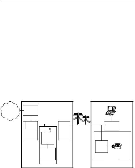
The following illustration shows a high-level view of an example Hotwire configuration.
Central Office (CO) |
Customer Premises (CP) |
Network |
Hotwire |
|
|
Data |
Service |
IPC |
|
|
Interface |
Provider |
Ethernet |
|
|
|
|
|
|
||
|
DSL |
|
|
SN |
|
CARD |
|
POTS/DSL |
|
|
|
|
||
|
DSLAM |
CO |
MDF |
|
|
|
POTS |
||
|
|
|
||
|
|
POTS |
|
Voice |
|
|
Splitter |
|
Interface |
|
|
|
|
CP |
|
|
|
|
POTS |
|
|
Switched |
|
Splitter |
|
|
|
|
|
|
|
Network |
|
|
|
|
Optional |
|
Optional |
|
|
|
|
|
Legend: DSL – Digital Subscriber Line |
IPC – Interworking Packet Concentrator |
MDF – Main Distribution Frame |
POTS – Plain Old Telephone Service |
SN – Service Node |
99-15674-03 |
|
2

The 8610 DSLAM accepts the following types of cards:
HManagement Control Processor (MCP). This is a processor card that administers and provides diagnostic connectivity to the DSL cards. It acts as a mid-level manager and works in conjunction with an SNMP network management system, such as HP OpenView, via its LAN port. It gathers operational status for each of the DSL cards and responds to the SNMP requests. It also has a serial port for local terminal access.
HMVL, RADSL and DSL cards. These cards provide a processor and an Ethernet interface to the NSP. The processor controls the modems and forwards the packet traffic to and from the Ethernet and DSL interfaces. Models include:
Ð8310 4-port and 8312 12-port Multiple Virtual Lines (MVL) cards that interoperate with the Hotwire 6310 modem.
Ð8510 Rate Adaptive Digital Subscriber Line (RADSL) card that interoperates with the 5620 Remote Termination Unit (RTU).
Ð8540 Digital Subscriber Line (DSL) card that interoperates with either the 5216 or 5246 Remote Termination Unit (RTU).
Ð8546 DSL card that interoperates with the 5446 RTU.
HMultirate High-bit-rate Digital Subscriber Line (M/HDSL) card.
HMultirate Symmetric Digital Subscriber Line (M/SDSL) card.
NOTE:
RADSL, MVL, M/HDSL and M/SDSL cards are generically referred to as DSL cards in this document.
Hotwire 8610 DSLAM Features
The Hotwire 8610 DSLAM chassis has the following features:
HPower Redundancy
Two versions of the Hotwire 8610 DSLAM chassis are available:
Ðac power
Ðdc power
The ac version can also be connected to a dc source to provide power redundancy. When using the dc version, two separate dc sources may be employed to provide power redundancy. If one power source fails, the other source provides all of the power needed by the system. This is done automatically without system disruption.
The dc version requires a source of ±48 Vdc, while the ac version will operate from 100 to 250 volts ac, 50 to 60 Hz.
3

HStackable Chassis for DSL Access Growth
Each chassis is an independent, standalone system. The 8610 and 8600 chassis are interoperable in a stack. The stackable design provides for six systems to share management access through a single MCP card (for 8610) or MCC card (for 8600) which, in turn, allows an additional slot for a DSL card in each of up to five additional systems. In a stacked configuration, the first or base chassis is equipped with an MCP/MCC card in Slot 1 leaving Slots 2 and 3 available for up to two DSL cards.
Each additional system will accept up to three DSL cards.
A Hotwire 8610 or 8600 DSLAM chassis can be added or removed from the stack without disrupting data service to the other items in the stack. However, management service will be disrupted.
The base system is connected to additional systems by connecting the 8-pin modular expansion cable provided from the OUT port of the base chassis to the IN port of the next chassis in the stack.
HHot Swappable Cards
The MCP and DSL cards can be installed and removed from the Hotwire 8610 DSLAM chassis without service disruption. You can replace a card without powering down the chassis and disrupting service to the other cards.
HPrimary Network Management Support via SNMP
SNMP management of the DSL cards is accomplished over a single Ethernet connection to the MCP card from a Network Management System (NMS) (such as Paradyne's DCE Manager for HP OpenView). The MCP card gathers all management information for each of the DSL cards and responds to the SNMP requests on behalf of the cards.
For a list of specific management information bases (MIBs) supported, see the appropriate Hotwire DSLAM Network Configuration Guide.
4
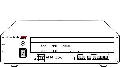
Hotwire 8610 DSLAM Components
TM
TM
8610
ESD 
MCP/
DSL
48VDC CLASS 2 OR LIMITED PWR SOURCE
AC
INPUT
SYSTEM |
OK |
Alrm |
Test |
|
ETHERNET |
TX |
RX |
Col |
|
DSL |
PORT 1 |
2 |
3 |
4 |
|
|
|
|
|
RADSL |
8546 |
|
|
|
|
|
ETHERNET |
|
|
|
|
|
|
|
|
|
|
|
|
|
|
||||
SYSTEM |
|
OK |
Alrm |
Test |
|
TX |
RX |
Coll |
|
|
|
|
|
|
|
|
|
|
|
MCP |
8000 |
|
|
|
|
|
|
|
|
|
|
|
|
|
|
|
|
|
|
|
|
|
|
||
|
|
|
|
|
DC FUSES |
|
|
|
|
|
|
|
|
|
|
MANAGEMENT |
|
10 BASE T |
|
|
||
|
|
|
|
|
T4A, MIN. 48V |
|
|
FAN |
|
PWR |
|
|
|
|
|
|
|
|
|
|
||
|
|
|
|
|
|
|
|
|
|
|
|
|
|
|
4 5 6 |
|
|
|
|
|
|
|
|
|
|
|
|
|
|
|
|
|
|
|
|
|
|
3 |
|
|
|
|
|
|
|
|
|
|
|
|
|
|
|
|
|
|
|
|
|
|
2 |
|
|
|
|
|
|
|
|
|
|
|
|
|
|
|
|
ALM |
A |
|
B |
|
|
1 |
|
|
|
|
|
|
|
A B |
A B |
|
|
A |
B |
|
|
|
|
|
STACK |
IN |
OUT |
SERIAL |
ALM INTF MCP/1 |
2 |
3 |
|
||||
|
|
|
|
|
|
|
|
|
|
|
||||||||||||
48V |
RTN |
|
|
|
|
|
|
|
|
|
|
|
|
POSITION |
|
|
|
|
|
|
|
|
3
2
1
99-16311
The Hotwire 8610 DSLAM consists of the following components:
HHotwire 8610 DSLAM base chassis
Hotwire 8610 DSLAM is a 3-slot chassis designed to house one MCP card in the first slot and up to two DSL cards in the remaining slots. Since the MCP card in the 8610 system can provide management connectivity for up to five other 8610 DSLAMs, these other systems can use the first slot for a DSL card, thus housing up to three DSL cards.
HOne Management Control Processor (MCP) card
The Hotwire 8610 DSLAM requires one MCP card mounted in Slot 1 of the base, or first, chassis in a stack. The MCP card is a processor card that administers and provides diagnostic connectivity to DSL cards in from one to six 8610 DSLAMs. It acts as a mid-level manager and works in conjunction with an SNMP network management system, such as HP OpenView, via its LAN port. It gathers operational status for each of the DSL cards and responds to the SNMP requests. It also supports a serial port for local terminal access.
HAt least one Digital Subscriber Line (DSL) card
The 8610 DSLAM requires at least one DSL card. Each DSL card contains a number of DSL ports (depending on model), Ethernet interface circuitry, and a processor. The processor controls the modems and forwards the packet traffic to and from the Ethernet and DSL interfaces.
NOTE:
You must order the MCP and DSL cards separately. They are not provided with the chassis.
5

Preinstallation Considerations
Consider the following before performing installation of the 8610 chassis:
HInstallation Site
Your installation site should be well ventilated, clean, and free of environmental extremes. If you are installing the Hotwire 8610 DSLAM chassis in a central office rack, make sure there is 2 to 3 feet of clearance at the front of the rack in which the 8610 chassis is to be installed to allow access for the installation of the chassis, circuit cards, and cables. Also allow for proper clearance at the rear of the chassis for cabling, if using the rear cable connectors.
HPower
The ac power version requires a power source of 100±250 Vac @ 50±60 Hz; maximum current draw is 3 amps @ 110 Vac.
The dc power version requires a ±48 Vdc power source (±40.0 to ±60.0 Vdc; maximum current draw is 2 amps). The size of power source wires must be between 14 AWG and 18 AWG, and can be either solid or stranded. However, 16 AWG stranded wire is recommended.
HGrounding
A ground lug is located at the lower right of the cover at the rear. It accepts 14 AWG wire.
A noninsulated banana jack is located at the left front side of the unit to provide a ground for the ESD wrist strap plug.
HStacking
Up to three 8610 chassis may be physically stacked safely on top of each other. However, for stacks of more than three, start a second stack or mount in a 19or 23-inch rack. Contact your sales representative for ordering information.
HCabling
Use only CAT3 or better twisted-pair network connection cables for DSL Termination Unit connections and interface patch cabling. Untwisted analog cables of any length anywhere in the loop substantially contribute to crosstalk and reduced loop reach.
The following customer-provided cables and cable adapters are required with this product:
ÐPlug-ended Telco 50-pin cable for connection from the Hotwire 8610 DSLAM Line ports to the CO POTS splitter shelf or MDF, one cable per DSL card.
Ð8-pin UTP (Unshielded Twisted Pair) CAT5 modular cable for connection to
the DSL 10BaseT Ethernet ports. You will need this cable for accessing the LAN/WAN circuits of each DSL card.
Ð8-pin UTP CAT5 modular cable for connection from the Hotwire 8610 DSLAM MANAGEMENT MCP port to a 10BaseT hub connector (connected to an SNMP management system network) for Slot 1 in the base chassis. For other chassis in a stack, use this cable for daisy chaining the chassis together. For M/HDSL and M/SDSL cards, refer to the appropriate card Installation Instructions for the correct cable needed.
6

Ð14-foot serial cable and DB25 and DB9 adapters are shipped with the MCP card. For connection to a modem, you will need a NULL modem adapter.
If there is adequate maintenance space at the rear of the rack, mount the chassis on the rack before installing cables. If there is inadequate space to do this, install the rear-mounted network connectors on the chassis before mounting the chassis on the rack.
CAUTION:
Use of any nontwisted pair wiring arrangements, such as jumpers, can cause reduction in overall DSL reach performance, even over short distances.
NOTE:
Each Hotwire 8610 DSLAM chassis weighs approximately nine pounds (with circuit cards) and can be easily installed by one installer.
Unpacking the Hardware
When shipped, the Hotwire 8610 DSLAM chassis is packed in a cardboard shipping container. Carefully remove the 8610 chassis from its shipping container and check for physical damage. If the 8610 chassis shows signs of shipping damage, report this immediately to your shipping and sales representatives.
Package Contents
The Hotwire 8610 DSLAM chassis, as shipped, consists of the following:
HThree filler plates installed in Slots 1, 2, and 3.
Hac power cord (if your chassis has the ac power option)
HTwo reversible mounting brackets (for 19and 23-inch rack mounting)
HAssociated hardware bundled in a plastic bag:
ÐFour #10-32 mounting screws
ÐFour #12-24 mounting screws and four #12-24 Speed Nuts (for use with racks without threaded mounting holes)
ÐFour #8-32 Phillips pan-head screws for center mounting
ÐThree #4-40 Phillips pan-head screws (to replace longer Telco captive screws when using the rear-mounted connectors)
NOTE:
The Hotwire 8610 DSLAM chassis requires an MCP card and at least one DSL card for proper functionality. These cards are not provided as part of the 8610 chassis and must be ordered separately.
7

Be sure to register your warranty at www.paradyne.com. Select Service & Support → Warranty Registration.
Mounting Configurations
The Hotwire 8610 DSLAM chassis can be mounted in any commercial Electronic Industries Association (EIA) standard 19or 23-inch rack. Both 19and 23-inch rack-mounting hardware is provided with the unit. In a typical mounting configuration, up to 14 Hotwire 8610 DSLAM chassis can be mounted in a 7-foot rack. This illustration shows the Hotwire 8610 DSLAM chassis installed in a rack.
8610
ESD 
MCP/
DSL
AC
INPUT |
48V |
RTN |
|
A B |
A B |
8610
ESD 
MCP/
DSL
AC
INPUT |
48V |
RTN |
|
A B |
A B |
8610
ESD 
MCP/
DSL
AC
INPUT |
48V |
RTN |
|
A B |
A B |
|
|
|
|
|
|
RADSL |
8546 |
3 |
|
|
|
|
|
|
RADSL |
8546 |
2 |
|
|
|
|
|
|
MCP |
8000 |
1 |
|
MANAGEMENT |
|
|
10 BASE T |
|
|
|
|
IN |
OUT |
SERIAL |
ALM INTF |
MCP/1 |
2 |
3 |
|
|
|
|
|
|
|
|
RADSL |
8546 |
3 |
|
|
|
|
|
|
RADSL |
8546 |
2 |
|
|
|
|
|
|
MCP |
8000 |
1 |
|
MANAGEMENT |
|
|
10 BASE T |
|
|
|
|
IN |
OUT |
SERIAL |
ALM INTF |
MCP/1 |
2 |
3 |
|
|
|
|
|
|
|
|
RADSL |
8546 |
3 |
|
|
|
|
|
|
RADSL |
8546 |
2 |
|
|
|
|
|
|
MCP |
8000 |
1 |
|
MANAGEMENT |
|
|
10 BASE T |
|
|
|
|
IN |
OUT |
SERIAL |
ALM INTF |
MCP/1 |
2 |
3 |
|
|
99-16309
In addition, the Hotwire 8610 DSLAM chassis can be placed on a desk or table, and stacked on top of each other. For stability, do not set more than three Hotwire 8610 chassis on top of each other in a single stack on a desk or tabletop. Two physical stacks of three chassis can be interconnected to provide shared management access for six
Hotwire 8610 chassis.
8610
AC
INPUT
8610
AC
INPUT
8610
AC
INPUT
3
2
1
3
2
1
3
2
1
99-16310
NOTE:
In this guide, the term rack refers to a CO rack, cabinet, frame, or bay.
8
Hotwire 8610 DSLAM Chassis Installation
The Hotwire 8610 DSLAM chassis is designed to be stacked one on top of the other on a desktop or table, or mounted in a 19-or 23-inch rack (front or center mount). Up to three 8610 chassis can be stacked on a table or desktop. Mounting brackets are provided for mounting in 19or 23-inch racks.
You will need a large, flat-blade screwdriver and a Phillips screwdriver to install the 8610 chassis in a commercial EIA-standard 19or 23-inch rack. You will need a small phillips screwdriver to change the STACK POSITION switch.
Stacking the 8610 Chassis
" Procedure
To stack the 8610 chassis on a desktop or table, select the stack position, and interconnect the stack:
1.Place the first Hotwire 8610 DSLAM chassis on a desktop or table.
2.Place the second Hotwire 8610 DSLAM chassis directly on top of the first chassis.
3.Place the third Hotwire 8610 DSLAM chassis directly on top of the second chassis.
4.Change the setting of the rotary STACK POSITION switch to the appropriate position of the chassis using a small Phillips screwdriver. Examine the switch closely to be sure the switch is set so that the notch points to the position number.
ÐThe base chassis containing the MCP card must be set to Stack Position 1.
ÐThe chassis directly on top of the base chassis must be set to Stack Position 2.
ÐThe chassis directly on top of the second chassis must be set to Stack Position 3.
ÐStart a second stack for chassis four through six with the Stack Position switch set appropriately.
Stack
Position 3
Stack |
3 |
4 5 6 . |
Position 2 |
2 |
1 . .. |
|
STACK
POSITION
3 |
4 5 6 . |
2 |
1 . .. |
|
STACK |
POSITION
Base Unit
Stack Position 1
8610
AC
INPUT
8610
AC
INPUT
8610
AC
INPUT
3 |
4 5 6 . |
2 |
1 . .. |
|
STACK |
POSITION
3
2
1
3
2
1
3
2
1
99-16312
9

Interconnecting 8610 Systems
" Procedure
To interconnect multiple 8610 systems:
1.Connect the end of an 8-pin modular cable into the Management OUT port of the base chassis.
2.Dress the 8-pin modular cable to the left and under the chassis, behind the foot, and up the side of the unit.
3.Plug the other end of the 8-pin modular cable into the Management IN port of the 8610 chassis above, dressing the cable as in the previous step.
4.Repeat for the next 8610 chassis, connecting the Management OUT port of Chassis 2 to the Management IN port of Chassis 3.
NOTE:
Bus cables must use Unshielded Twisted Pair (UTP) CAT5 cable. The total bus cabling should not exceed 25 feet.
10
Loading...