


6381-A3

6381-A3 Router
User’s Guide
Document No. 6381-A2-GB23-10
January 2005

Copyright © 2005 Paradyne Corporation.
All rights reserved.
Printed in U.S.A.
Notice
This publication is protected by federal copyright law. No part of this publication may be copied or distributed,
transmitted, transcribed, stored in a retrieval system, or translated into any human or computer language in any form or
by any means, electronic, mechanical, magnetic, manual or otherwise, or disclosed to third parties without the express
written permission of Paradyne Corporation, 8545 126th Ave. N., Largo, FL 33773.
Paradyne Corporation makes no representation or warranties with respect to the contents hereof and specifically
disclaims any implied warranties of merchantability or fitness for a particular purpose. Further, Paradyne Corporation
reserves the right to revise this publication and to make changes from time to time in the contents hereof without
obligation of Paradyne Corporation to notify any person of such revision or changes.
Changes and enhancements to the product and to the information herein will be documented and issued as a new
release to this manual.
Warranty, Sales, Service, and Training Information
Contact your local sales representative, service representative, or distributor directly for any help needed. For additional
information concerning warranty, sales, service, repair, installation, documentation, training, distributor locations, or
Paradyne worldwide office locations, use one of the following methods:
Internet: Visit the Paradyne World Wide Web site at www.paradyne.com. (Be sure to register your warranty at
www.paradyne.com/warranty.)
Telephone: Call our automated system to receive current information by fax or to speak with a company
representative.
— Within the U.S.A., call 1-800-870-2221
— Outside the U.S.A., call 1-727-530-2340
Document Feedback
We welcome your comments and suggestions about this document. Please mail them to Technical Publications,
Paradyne Corporation, 8545 126th Ave. N., Largo, FL 33773, or send e-mail to userdoc@paradyne.com. Include the
number and title of this document in your correspondence. Please include your name and phone number if you are
willing to provide additional clarification.
Trademarks
Acculink, Bitstorm, Comsphere, DSL the Easy Way, ETC, Etherloop, FrameSaver, GranDSLAM, GrandVIEW, Hotwire,
the Hotwire logo, iMarc, Jetstream, MVL, NextEDGE, Net to Net Technologies, OpenLane, Paradyne, the Paradyne
logo, Paradyne Credit Corp., the Paradyne Credit Corp. logo, Performance Wizard, ReachDSL, StormPort, TruePut are
registered trademarks of Paradyne Corporation.
ADSL/R, Connect to Success, Hotwire Connected, JetFusion, JetVision, MicroBurst, PacketSurfer, Quick Channel,
Reverse Gateway, Spectrum Manager, and StormTracker are trademarks of Paradyne Corporation.
All other products or services mentioned herein are the trademarks, service marks, registered trademarks, or
registered service marks of their respective owners.
A January 2005 6381-A2-GB23-10

!
Important Safety Instructions
1. Read and follow all warning notices and instructions marked on the product or included in the manual.
2. Slots and openings in the cabinet are provided for ventilation. To ensure reliable operation of the product and to
protect it from overheating, these slots and openings must not be blocked or covered.
3. Do not allow anything to rest on the power cord and do not locate the product where persons will walk on the power
cord.
4. Do not attempt to service this product yourself, as opening or removing covers may expose you to dangerous high
voltage points or other risks. Refer all servicing to qualified service personnel.
5. General purpose cables are used with this product for connection to the network. Special cables, which may be
required by the regulatory inspection authority for the installation site, are the responsibility of the customer. Use a
UL Listed, CSA certified, minimum No. 24 AWG line cord for connection to the Digital Subscriber Line (DSL)
network.
6. When installed in the final configuration, the product must comply with the applicable Safety Standards and
regulatory requirements of the country in which it is installed. If necessary, consult with the appropriate regulatory
agencies and inspection authorities to ensure compliance.
7. A rare phenomenon can create a voltage potential between the earth grounds of two or more buildings. If products
installed in separate buildings are interconnected, the voltage potential may cause a hazardous condition. Consult
a qualified electrical consultant to determine whether or not this phenomenon exists and, if necessary, implement
corrective action prior to interconnecting the products.
8. Input power to this product must be provided by one of the following: (1) a UL Listed/CSA certified power source
with a Class 2 or Limited Power Source (LPS) output for use in North America, or (2) a certified transformer, with a
Safety Extra Low Voltage (SELV) output having a maximum of 240 VA available, for use in the country of
installation.
9. In addition, since the equipment is to be used with telecommunications circuits, take the following precautions:
— Never install telephone wiring during a lightning storm.
— Never install telephone jacks in wet locations unless the jack is specifically designed for wet locations.
— Never touch uninsulated telephone wires or terminals unless the telephone line has been disconnected at the
network interface.
— Use caution when installing or modifying telephone lines.
— Avoid using a telephone (other than a cordless type) during an electrical storm. There may be a remote risk of
electric shock from lightning.
— Do not use the telephone to report a gas leak in the vicinity of the leak.
CE Marking
When the product is marked with the CE mark on the equipment label, a supporting Declaration of Conformity may be
downloaded from the Paradyne World Wide Web site at www.paradyne.com. Select Library → Technical Manuals →
CE Declarations of Conformity.
FCC Part 15 Declaration
An FCC Declaration of Conformity may be downloaded from the Paradyne World Wide Web site at www.paradyne.com.
Select Support -> Technical Manuals -> Declarations of Conformity.
This device complies with Part 15 of the FCC Rules. Operation is subject to the following two conditions: (1) this device
may not cause harmful interference, and (2) this device must accept any interference received, including interference
that may cause undesired operation.
The authority to operate this equipment is conditioned by the requirement that no modifications will be made to the
equipment unless the changes or modifications are expressly approved by the responsible party.
6381-A2-GB23-10 January 2005 B

This equipment has been tested and found to comply with the limits for a Class B digital device, pursuant to Part 15 of
the FCC Rules. These limits are designed to provide reasonable protection against harmful interference in a residential
installation. This equipment generates, uses, and can radiate radio frequency energy and, if not installed and used in
accordance with the instructions, may cause harmful interference to radio communications. However, there is no
guarantee that interference will not occur in a particular installation. If this equipment does cause harmful interference
to radio or television reception, which can be determined by turning the equipment off and on, the user is encouraged to
try to correct the interference by one or more of the following measures:
Reorient or relocate the receiving antenna.
Increase the separation between the equipment and receiver.
Connect the equipment into an outlet on a circuit different from that to which the receiver is connected.
Consult the dealer or an experienced radio/TV technician for help.
Notice to Users of the United States Telephone Network
The following notice applies to versions of the modem that have been FCC Part 68 approved.
This equipment complies with Part 68 of the FCC rules and the requirements adopted by the Administrative Council for
Terminal Attachment (ACTA). On the bottom side of this equipment is a label that contains, among other information, a
product identifier in the format US:AAAEQ##TXXXX. If requested, this number must be provided to the Telephone
Company.
This equipment is intended to connect to the Public Switched Telephone Network through a Universal Service Order
Code (USOC) type RJ11C jack. A plug and jack used to connect this equipment to the premises wiring and telephone
network must comply with the applicable FCC Part 68 rules and requirements adopted by the ACTA. A compliant
telephone cord and modular plug is provided with this product. It has been designed to be connected to a compatible
modular jack that is also compliant.
The Ringer Equivalence Number (or REN) is used to determine the number of devices that may be connected to a
telephone line. Excessive RENs on a telephone line may result in the devices not ringing in response to an incoming
call. In most but not all areas, the sum of RENs should not exceed five (5.0). To be certain of the number of devices that
may be connected to a line, as determined by the total RENs, contact the local Telephone Company. The REN for this
product is part of the product identifier that has the format US:AAAEQ##TXXXX. The digits represented by ## are the
REN without a decimal point. For example, 03 represents a REN of 0.3.
If the modem causes harm to the telephone network, the Telephone Company will notify you in advance that temporary
discontinuance of service may be required. But if advance notice is not practical, the Telephone Company will notify the
customer as soon as possible. Also, you will be advised of your right to file a complaint with the FCC if you believe it is
necessary.
The Telephone Company may make changes in its facilities, equipment, operations or procedures that could affect the
operation of the equipment. If this happens, the Telephone Company will provide advance notice in order for you to
make necessary modifications to maintain uninterrupted service. If trouble is experienced with the modem, refer to the
repair and warranty information in this document.
If the equipment is causing harm to the telephone network, the Telephone Company may request that you disconnect
the equipment until the problem is resolved.
The user may make no repairs to the equipment.
Connection to party line service is subject to state tariffs. Contact the state public utility commission, public service
commission or corporation commission for information.
If the site has specially wired alarm equipment connected to the telephone line, ensure the installation of the modem
does not disable the alarm equipment. If you have questions about what will disable alarm equipment, consult your
Telephone Company or a qualified installer.
C January 2005 6381-A2-GB23-10

Supplier's Declaration of Conformity
Place of Issue:
Paradyne Corporation
8545 126th Avenue North
Largo, FL 33773-1502
USA
Date of Issue: 4/2/2004
Paradyne Corporation, located at the above address, hereby certifies that Model Number 6381-A2-210, bearing
labeling identification number US:AW2DL03B6381-AX, complies with: the Federal Communications Commission's
("FCC") Rules and Regulations 47 CFR Part 68, the Administrative Council on Terminal Attachments ("ACTA")-adopted
technical criteria TIA-968-A, "Telecommunications - Telephone Terminal Equipment -Technical Requirements for
Connection of Terminal Equipment To the Telephone Network, October 2002."
Patrick Mur phy
Senior Vice President, Chief Financial Officer
Notice to Users of the Canadian Telephone Network
NOTICE: This equipment meets the applicable Industry Canada Terminal Equipment Technical Specifications. This is
confirmed by the registration number. The abbreviation IC before the registration number signifies that registration was
performed based on a Declaration of Conformity indicating that Industry Canada technical specifications were met. It
does not imply that Industry Canada approved the equipment.
NOTICE: The Ringer Equivalence Number (REN) for this terminal equipment is labeled on the equipment. The REN
assigned to each terminal equipment provides an indication of the maximum number of terminals allowed to be
connected to a telephone interface. The termination on an interface may consist of any combination of devices subject
only to the requirement that the sum of the Ringer Equivalence Numbers of all the devices does not exceed five.
If your equipment is in need of repair, contact your local sales representative, service representative, or distributor
directly.
!
CANADA - EMI NOTICE:
This Class B digital apparatus meets all requirements of the Canadian interference-causing equipment regulations.
Cet appareil numérique de la classe B respecte toutes les exigences du règlement sur le matérial brouilleur du
Canada.
6381-A2-GB23-10 January 2005 D

Japan Notices
This is a Class B product based on the standard of the Voluntary Control Council for
Interference from Information Technology Equipment (VCCI). If this is used near a radio or
television receiver in a domestic environment, it may cause radio interference. Install and use
the equipment according to the instruction manual.
E January 2005 6381-A2-GB23-10

Contents
About This Guide
1 Introduction
Document Purpose and Intended Audience . . . . . . . . . . . . . . . . . . . . v
Document Summary . . . . . . . . . . . . . . . . . . . . . . . . . . . . . . . . . . . . . . v
Product-Related Documents . . . . . . . . . . . . . . . . . . . . . . . . . . . . . . . . vi
Definitions . . . . . . . . . . . . . . . . . . . . . . . . . . . . . . . . . . . . . . . . . . . . . . 1-1
Features of the 6381 Router . . . . . . . . . . . . . . . . . . . . . . . . . . . . . . . . 1-1
System Requirements . . . . . . . . . . . . . . . . . . . . . . . . . . . . . . . . . . . . . 1-2
Ports and Buttons (Back Panel) . . . . . . . . . . . . . . . . . . . . . . . . . . . . . . 1-2
LED Description (Front Panel) . . . . . . . . . . . . . . . . . . . . . . . . . . . . . . . 1-3
Packing List . . . . . . . . . . . . . . . . . . . . . . . . . . . . . . . . . . . . . . . . . . . . . 1-4
2 Hardware Installation and PC Setup
Overview . . . . . . . . . . . . . . . . . . . . . . . . . . . . . . . . . . . . . . . . . . . . . . . 2-1
Connecting the Hardware . . . . . . . . . . . . . . . . . . . . . . . . . . . . . . . . . . 2-1
Configuring Your PC . . . . . . . . . . . . . . . . . . . . . . . . . . . . . . . . . . . . . . 2-3
Windows USB Driver Installation . . . . . . . . . . . . . . . . . . . . . . . . . . . . . 2-3
Configuring Your PC’s IP Address . . . . . . . . . . . . . . . . . . . . . . . . . . . . 2-6
Assigning an IP Address to your PC Automatically by DHCP . . . . 2-6
Windows XP . . . . . . . . . . . . . . . . . . . . . . . . . . . . . . . . . . . . . . . . . 2-6
Windows 2000 . . . . . . . . . . . . . . . . . . . . . . . . . . . . . . . . . . . . . . . . 2-8
Windows ME . . . . . . . . . . . . . . . . . . . . . . . . . . . . . . . . . . . . . . . . . 2-9
Windows 95, 98 . . . . . . . . . . . . . . . . . . . . . . . . . . . . . . . . . . . . . . . 2-10
Windows NT 4.0 . . . . . . . . . . . . . . . . . . . . . . . . . . . . . . . . . . . . . . 2-11
3 Using the Web Interface
Logging Into Your Router . . . . . . . . . . . . . . . . . . . . . . . . . . . . . . . . . . . 3-1
Home Page . . . . . . . . . . . . . . . . . . . . . . . . . . . . . . . . . . . . . . . . . . . . . 3-2
Quick Start . . . . . . . . . . . . . . . . . . . . . . . . . . . . . . . . . . . . . . . . . . . . . . 3-2
6381-A2-GB23-10 January 2005 i

Contents
Setup . . . . . . . . . . . . . . . . . . . . . . . . . . . . . . . . . . . . . . . . . . . . . . . . . . 3-5
Wide Area Network Connection. . . . . . . . . . . . . . . . . . . . . . . . . . . 3-5
Local Area Network Connection . . . . . . . . . . . . . . . . . . . . . . . . . . 3-5
Saving Changes . . . . . . . . . . . . . . . . . . . . . . . . . . . . . . . . . . . . . . 3-5
Configuring the WAN . . . . . . . . . . . . . . . . . . . . . . . . . . . . . . . . . . . . . . 3-6
New Connection . . . . . . . . . . . . . . . . . . . . . . . . . . . . . . . . . . . . . . . . . . 3-7
PPPoE Connection Setup . . . . . . . . . . . . . . . . . . . . . . . . . . . . . . . 3-7
PPPoA Connection Setup . . . . . . . . . . . . . . . . . . . . . . . . . . . . . . . 3-9
Static Connection Setup . . . . . . . . . . . . . . . . . . . . . . . . . . . . . . . . 3-11
DHCP Connection Setup . . . . . . . . . . . . . . . . . . . . . . . . . . . . . . . . 3-12
Bridged Connection . . . . . . . . . . . . . . . . . . . . . . . . . . . . . . . . . . . . 3-13
CLIP Connection . . . . . . . . . . . . . . . . . . . . . . . . . . . . . . . . . . . . . . 3-15
Modify an Existing Connection . . . . . . . . . . . . . . . . . . . . . . . . . . . . . . . 3-16
Modem Setup . . . . . . . . . . . . . . . . . . . . . . . . . . . . . . . . . . . . . . . . . . . . 3-17
TSML . . . . . . . . . . . . . . . . . . . . . . . . . . . . . . . . . . . . . . . . . . . . . . . . . . 3-17
Configuring the LAN . . . . . . . . . . . . . . . . . . . . . . . . . . . . . . . . . . . . . . . 3-18
Enable/Disable DHCP . . . . . . . . . . . . . . . . . . . . . . . . . . . . . . . . . . 3-19
Changing the Router's IP address . . . . . . . . . . . . . . . . . . . . . . . . . . . . 3-20
Firewall/NAT Services . . . . . . . . . . . . . . . . . . . . . . . . . . . . . . . . . . . . . 3-21
Advanced . . . . . . . . . . . . . . . . . . . . . . . . . . . . . . . . . . . . . . . . . . . . . . . 3-22
UPnP . . . . . . . . . . . . . . . . . . . . . . . . . . . . . . . . . . . . . . . . . . . . . . . 3-22
SNTP . . . . . . . . . . . . . . . . . . . . . . . . . . . . . . . . . . . . . . . . . . . . . . . 3-23
SNMP . . . . . . . . . . . . . . . . . . . . . . . . . . . . . . . . . . . . . . . . . . . . . . 3-24
IP QoS . . . . . . . . . . . . . . . . . . . . . . . . . . . . . . . . . . . . . . . . . . . . . . 3-25
Port Forwarding . . . . . . . . . . . . . . . . . . . . . . . . . . . . . . . . . . . . . . . 3-25
IP Filters. . . . . . . . . . . . . . . . . . . . . . . . . . . . . . . . . . . . . . . . . . . . . 3-27
LAN Clients . . . . . . . . . . . . . . . . . . . . . . . . . . . . . . . . . . . . . . . . . . 3-28
LAN Isolation . . . . . . . . . . . . . . . . . . . . . . . . . . . . . . . . . . . . . . . . . 3-28
Bridge Filters . . . . . . . . . . . . . . . . . . . . . . . . . . . . . . . . . . . . . . . . . 3-29
Multicast. . . . . . . . . . . . . . . . . . . . . . . . . . . . . . . . . . . . . . . . . . . . . 3-31
IGMP Snooping . . . . . . . . . . . . . . . . . . . . . . . . . . . . . . . . . . . . . . . 3-32
Static Routing . . . . . . . . . . . . . . . . . . . . . . . . . . . . . . . . . . . . . . . . 3-32
Dynamic Routing . . . . . . . . . . . . . . . . . . . . . . . . . . . . . . . . . . . . . . 3-33
Access Control. . . . . . . . . . . . . . . . . . . . . . . . . . . . . . . . . . . . . . . . 3-35
Log Out . . . . . . . . . . . . . . . . . . . . . . . . . . . . . . . . . . . . . . . . . . . . . . . . 3-35
ii January 2005 6381-A2-GB23-10

Tools . . . . . . . . . . . . . . . . . . . . . . . . . . . . . . . . . . . . . . . . . . . . . . . . . . 3-36
Status . . . . . . . . . . . . . . . . . . . . . . . . . . . . . . . . . . . . . . . . . . . . . . . . . . 3-41
4 Troubleshooting
The Router Is Not Functional . . . . . . . . . . . . . . . . . . . . . . . . . . . . . . . . 4-1
You Cannot Connect to the Router . . . . . . . . . . . . . . . . . . . . . . . . . . . 4-1
LEDs Blink in a Sequential Pattern . . . . . . . . . . . . . . . . . . . . . . . . . . . 4-2
The Status LED Continues to Blink . . . . . . . . . . . . . . . . . . . . . . . . . . . 4-2
The Status LED is Always Off . . . . . . . . . . . . . . . . . . . . . . . . . . . . . . . 4-2
Contents
System Commands . . . . . . . . . . . . . . . . . . . . . . . . . . . . . . . . . . . . 3-36
Remote Log . . . . . . . . . . . . . . . . . . . . . . . . . . . . . . . . . . . . . . . . . . 3-36
User Management . . . . . . . . . . . . . . . . . . . . . . . . . . . . . . . . . . . . . 3-37
Update Gateway . . . . . . . . . . . . . . . . . . . . . . . . . . . . . . . . . . . . . . 3-38
Analyzer. . . . . . . . . . . . . . . . . . . . . . . . . . . . . . . . . . . . . . . . . . . . . 3-39
Ping Test . . . . . . . . . . . . . . . . . . . . . . . . . . . . . . . . . . . . . . . . . . . . 3-39
Modem Test. . . . . . . . . . . . . . . . . . . . . . . . . . . . . . . . . . . . . . . . . . 3-40
A Terminology
Index
What is a Firewall? . . . . . . . . . . . . . . . . . . . . . . . . . . . . . . . . . . . . . . . . A-1
What is NAT? . . . . . . . . . . . . . . . . . . . . . . . . . . . . . . . . . . . . . . . . . . . . A-1
What is a DMZ? . . . . . . . . . . . . . . . . . . . . . . . . . . . . . . . . . . . . . . . . . . A-1
What is a Router? . . . . . . . . . . . . . . . . . . . . . . . . . . . . . . . . . . . . . . . . A-2
6381-A2-GB23-10 January 2005
iii

Contents
iv January 2005 6381-A2-GB23-10

About This Guide
Document Purpose and Intended Audience
This guide contains detailed information about the 6381-A3 router. It is intended
for all users of the router.
Document Summary
Section Description
Chapter 1, Introduction Describes the features of the router.
Chapter 2, Hardware
Installation and PC Setup
Chapter 3, Using the Web
Interface
Chapter 4, Troubleshooting Contains tips on troubleshooting common problems.
Appendix A, Terminology Explains some major internetworking concepts.
Index Lists key terms, concepts, and sections in alphabetical
A master glossary of terms and acronyms used in Paradyne documents is
available online at www.paradyne.com. Select Support → Technical Manuals →
Technical Glossary.
Shows how to connect the router and set up your PC to
manage the router.
Explains how to use the web interface to configure and
monitor the router.
order.
6381-A2-GB23-10 January 2005 v

About This Guide
Product-Related Documents
Complete documentation for Paradyne products is available online at
www.paradyne.com. Select Support → Technical Manuals.
To order a paper copy of a Paradyne document, or to speak with a sales
representative, please call 1-727-530-2000.
vi January 2005 6381-A2-GB23-10

Introduction
Definitions
1
Before you install or use your new router, you may find it helpful to understand the
following terms:
A bridge is a device that forwards any message from one part of a network to
another.
A router is a device that forwards messages according to their network
addresses.
ADSL is Asymmetric Digital Subscriber Line, a version of DSL that allows a
higher speed for information coming from the Internet to your PC
(“downstream”) than it does for information going to the Internet from your PC
(“upstream”).
ReachDSL is a version of DSL that works on lines too long or too noisy for
ADSL.
ADSL/R is technology that combines ADSL and ReachDSL in one device.
The Model 6381 is a Digital Subscriber Line (DSL) modem that may be set by you
to run in bridge or router mode. Because it is most frequently used as a router, that
is how it is referred to in this manual. It supports ADSL/R.
Features of the 6381 Router
Your router has the following features:
Support for ADSL2+ and ReachDSL (ADSL/R)
10/100BaseT Ethernet port
USB port
The ability to connect multiple PCs to the Internet with just one WAN IP
Address (when configured in router mode with NAT enabled)
A user-friendly web interface for configuration and monitoring
Single-session IPSec and PPTP passthrough for Virtual Private Network
(VPN)
6381-A2-GB23-10 January 2005 1-1

1. Introduction
Preconfigured port settings for many popular games
Ability to act as a DHCP Server on your network
Compatibility with virtually all standard Internet applications
Address filtering and DMZ hosting
Downloadable flash software upgrades
Support for up to eight Permanent Virtual Circuits (PVCs)
Support for up to two PPPoE sessions
System Requirements
In order to use your modem for Internet access, you must have the following:
ADSL service subscription from your ISP.
One computer with an Ethernet 10/100BaseT network interface card (NIC) or
a free USB port.
(Optional) An Ethernet hub or switch, if you are connecting the device to
several computers on an Ethernet network.
For system monitoring or configuration using the supplied web interface, a
web browser such as Internet Explorer Version 5.5 or later.
Ports and Buttons (Back Panel)
POWER is where you connect the power supply.
RESET Button: The RESET button is used to reset the router to the factory
default settings selected by your service provider. Do not use the RESET
button unless advised to by your service representative.
LAN (Local Area Network) port: This is used to connect to Ethernet network
devices, such as a PC, hub, switch, or router.
USB (Universal Serial Bus port): Connects to a PC's serial port. The router
supports Windows-based PCs using an RNDIS driver (included on the CD).
PHONE port: This allows a phone to directly connect to the router. You do not
need to add splitter to the phone you connect here, since the router has an
internal splitter.
LINE port: This is the DSL interface which connects directly to your phone line.
1-2 January 2005 6381-A2-GB23-10
LED Description (Front Panel)
Power LED: On indicates that the power is supplied to the router.
Status LED: The Status LED serves two purposes. If the LED is continuously
lit, the DSL interface is successfully connected to a device through the LINE
port. If the LED is flickering, it is an indication that the router is training
(negotiating the connection to its partner modem).
Activity LED: The Activity LED shows the state of the PPPoA or PPPoE
connection. Off: no PPP connection is established or the connection is not
used. Blinking: a PPP connection is being attempted. Solid green: a PPP
connection is established.
LAN LED: The LAN LED serves two purposes. If the LED is continuously lit,
the Ethernet interface is successfully connected to a device through the LAN
port. If the LED is flickering, it is an indication of network activity.
USB LED: The USB LED serves two purposes. If the LED is continuously lit,
the USB interface is successfully connected to a device through the LAN port.
If the LED is flickering, it is an indication of network activity.
1. Introduction
POWER
STATUS
ACTIVITY
LAN
USB
05-17610
6381-A2-GB23-10 January 2005
1-3

1. Introduction
Packing List
Your router is shipped with the following:
Power adapter
Ethernet cable (RJ45, straight-through wiring)
Phone cable (RJ11)
USB cable
CD-ROM containing this manual and USB drivers
USB
LAN
ACTIVITY
STATUS
ER
POW
04-17511
1-4 January 2005 6381-A2-GB23-10

Hardware Installation and PC Setup
Overview
This chapter provides basic instructions for connecting the router to a computer or
a LAN and to the Internet using DSL. The first part provides instructions to set up
the hardware, and the second part describes how to prepare your PC for use with
the router. Refer to Chapter 3, Using the Web Interface for router configuration
instructions.
It is assumed that you have already subscribed to DSL service with your telephone
company or other Internet service provider (ISP).
2
Connecting the Hardware
Shut down your PC before connecting the router. To connect your router:
Procedure
1. Connect the supplied modular phone cable to the LINE port, and connect the
other end of the cable to your phone jack.
2. If you would like to use a phone in the vicinity of the router, connect it to the
PHONE jack of the router using the cord that came with your telephone. The
router has an internal POTS filter, so you do not need to install one here.
3. Connect the USB port, the LAN port, or both.
— If you are connecting the router directly to a PC (rather than to a LAN), you
can use either the USB port or the LAN port. (Do not connect both the
USB port and the LAN port to the same PC.)
To use the USB port, connect the supplied USB cable to the USB port of
the router, then connect the other end of the cable to a free USB port on
your PC.
When you start your PC (in a later step), Windows will detect the new
hardware and initiate the Found New Hardware Wizard. Follow the
instructions under Windows USB Driver Installation on page 2-3.
— Alternatively, you can use the included Ethernet cable to connect your
computer directly to the router. Attach one end of the supplied Ethernet
6381-A2-GB23-10 January 2005 2-1

2. Hardware Installation and PC Setup
cable to the LAN port and connect the other end to the 10/100BaseT port
on the network interface card in your PC.
— If your LAN has more than one computer, you can attach one end of an
Ethernet cable to a hub or a switch and the other to the port labeled LAN
on the router. This probably will require an Ethernet crossover cable. See
the documentation for your hub or switch to be sure.
4. Connect the cylindrical power plug into the POWER connector on the back of
the device. Next:
— If you have a wall-mount adapter, plug the AC adapter into a wall outlet or
a power strip.
— If you have a table-top adapter, use the AC power cord to connect the
adapter to a wall outlet or power strip.
The supplied power adapter may look different than the one illustrated here.
5. Turn on your PC any other LAN devices, such as hubs or switches.
LINE LAN POWERPHONE USB
1
2
Figure 2-1. Hardware Installation
RESET
DEFAULT
4
3
OR
04-17510
2-2 January 2005 6381-A2-GB23-10
Configuring Your PC
Before you start to access the router via Ethernet, you must configure your PC's
TCP/IP address to be 192.168.1.x, where x is any number between 2 and 254.
The subnet mask must be 255.255.255.0. Your router's default IP address is
192.168.1.1.
If you used the Ethernet cable to connect your router and PC, you do not need any
specific driver installation and you can skip Windows USB Driver Installation,
below. If you used the USB cable on a PC running a Windows operation system,
install the provided USB driver.
Windows 95 and Windows NT 4.0 do not support USB without additional software
(not included with your router). If USB driver installation fails under those operating
systems, contact your service provider.
Windows USB Driver Installation
As soon as you connect the USB cable between your PC and the router, Windows
will detect new hardware and the Found New Hardware Wizard will pop up. To
install the USB driver:
2. Hardware Installation and PC Setup
Procedure
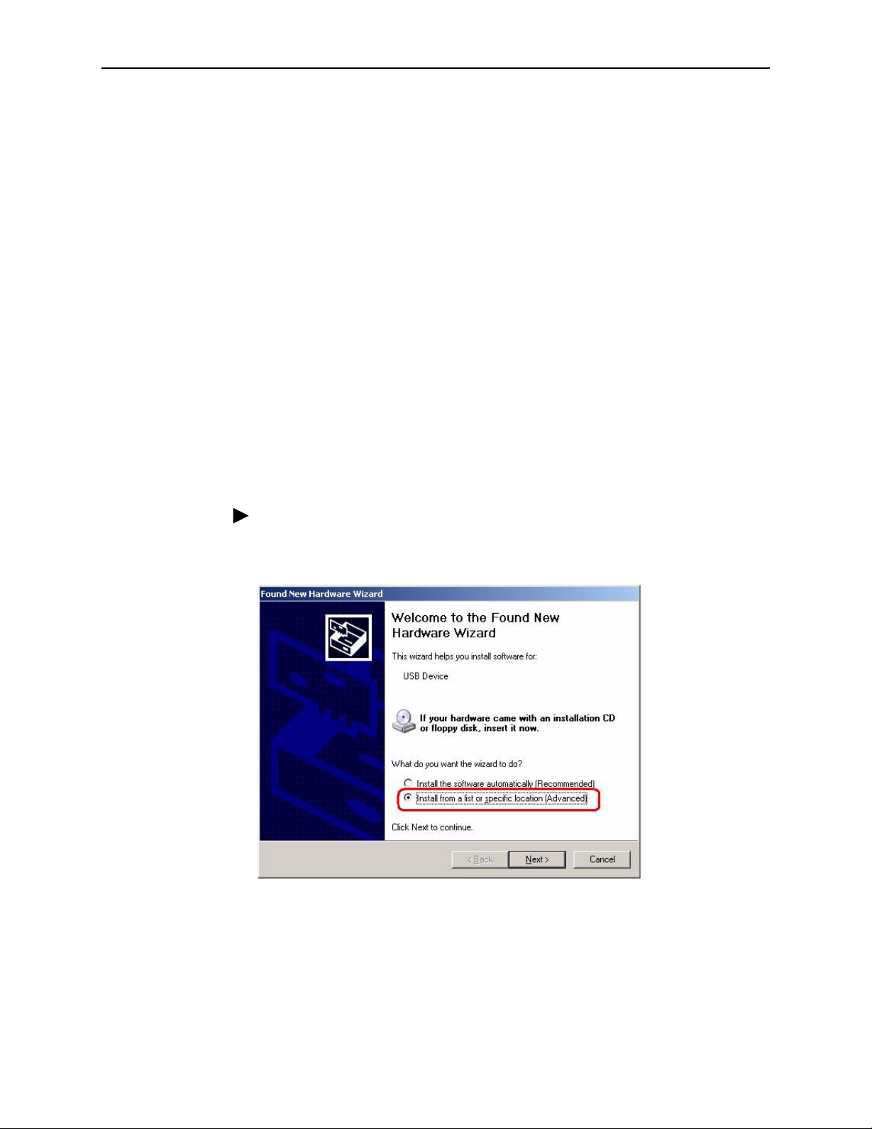
1. Choose "Install from a list or specific location" and click on Next (Figure 2-2).
Figure 2-2. Found New Hardware Wizard
6381-A2-GB23-10 January 2005
2-3
2. Hardware Installation and PC Setup
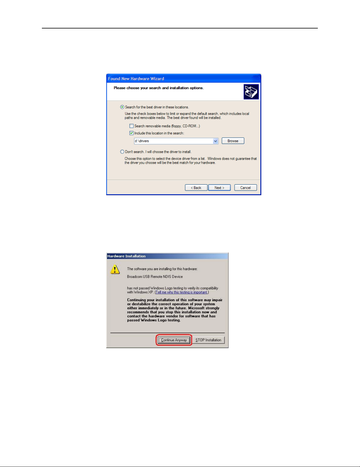
2. Insert the supplied CD and use Browse to include the location D:\drivers in the
search, where D: is the letter you use for your CD drive (Figure 2-3).
Figure 2-3. New Hardware Installation Options
3. The Wizard will ask you to confirm the hardware installation. Choose Continue
Anyway. Windows will then install the supplied USB driver on your PC
(Figure 2-4 and Figure 2-5).
Figure 2-4. Hardware Installation Confirmation
2-4 January 2005 6381-A2-GB23-10
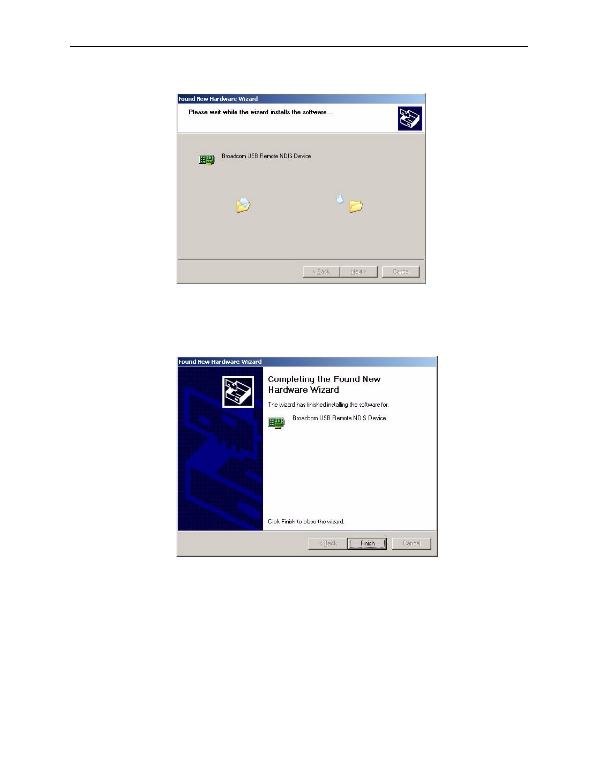
Figure 2-5. Hardware Installation
2. Hardware Installation and PC Setup
4. Click on Finish to close the Wizard at the completion page (Figure 2-6).
Figure 2-6. Completing the Found New Hardware Wizard
6381-A2-GB23-10 January 2005
2-5

2. Hardware Installation and PC Setup
Configuring Your PC’s IP Address
Before you start to access the router using the Ethernet or USB connection, you
must configure your PC's TCP/IP address to be 192.168.1.x, where x is any
number between 2 and 254. The subnet mask is 255.255.255.0.
Your router's default IP address is 192.168.1.1.
Assigning an IP Address to your PC Automatically by DHCP
To use the router's DHCP feature, click in the radio button labeled “Obtain an IP
address automatically” instead of “Use the following IP address” in the following
procedures.
By default, the LAN port IP address of the router is 192.168.1.1. (You can change
this address, or another address can be assigned by your ISP.)
Windows XP
To configure the IP address under Windows XP:
Procedure
1. In the Windows task bar, click on the Start button, and then click on Control
Panel.
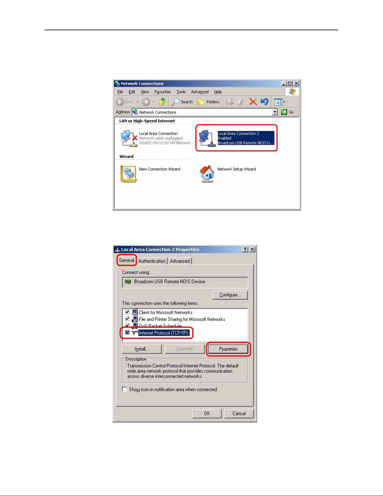
2. Double-click on the Network Connections icon.
3. In the LAN or High-Speed Internet window, right-click on the icon
corresponding to your network interface card (NIC) and select Properties.
(Often this icon is labeled Local Area Connection). The Local Area Connection
dialog box is displayed with a list of currently installed network items.
2-6 January 2005 6381-A2-GB23-10
2. Hardware Installation and PC Setup
4. Ensure that the check box to the left of the item labeled Internet Protocol
(TCP/IP) is checked, and click on Properties.
Figure 2-7. Network Connections in Windows XP
Figure 2-8. Local Area Connection Properties in Windows XP
6381-A2-GB23-10 January 2005
2-7
2. Hardware Installation and PC Setup
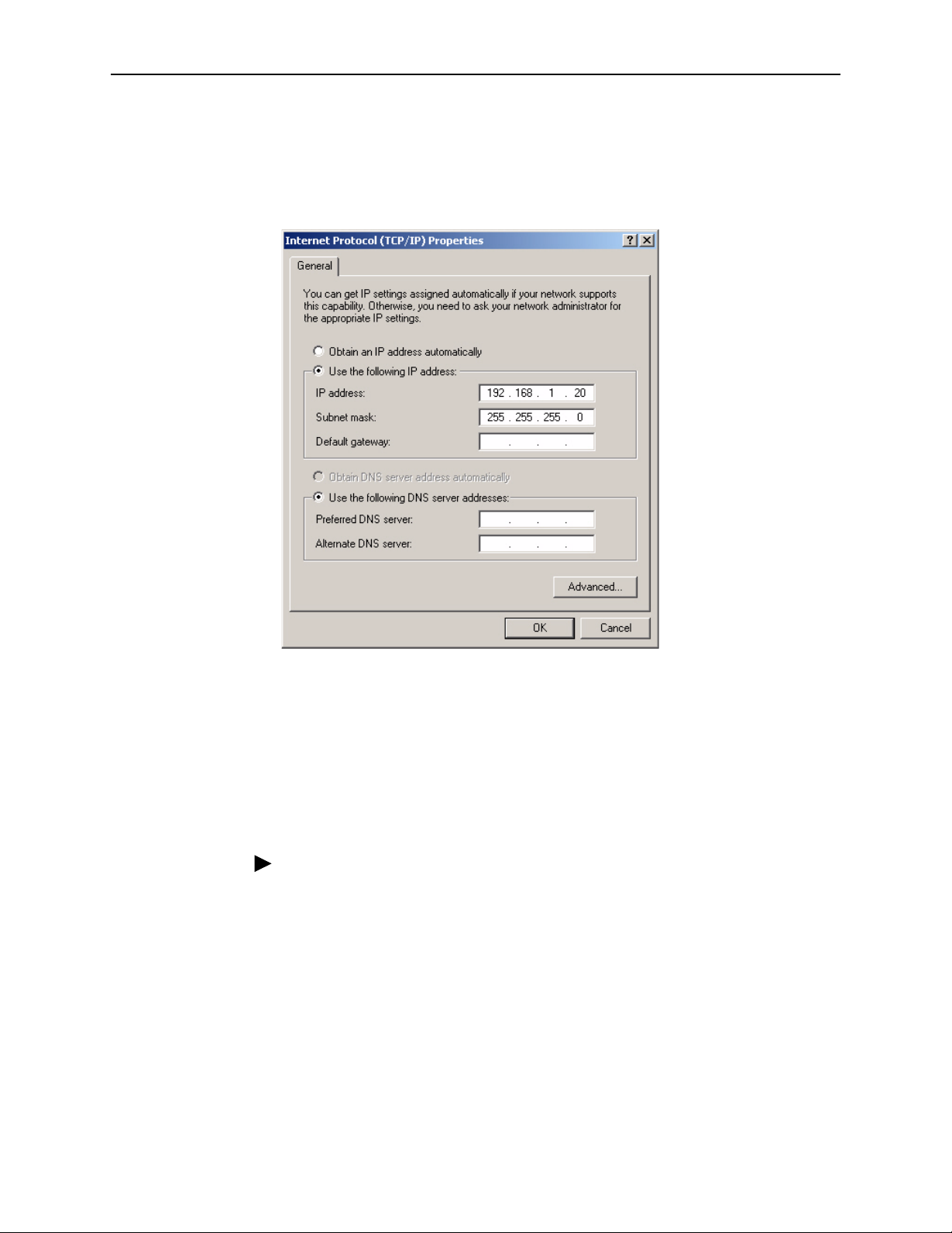
5. In the Internet Protocol (TCP/IP) Properties dialog box, click in the radio button
labeled “Use the following IP address” and type 192.168.1.x (where x is any
number between 2 and 254) in the IP Address field. Type 255.255.255.0 in the
Subnet Mask field.
Windows 2000
Figure 2-9. TCP/IP Properties in Windows XP
6. Click on OK twice to confirm your changes, and close the Control Panel.
To configure the IP address under Windows 2000:
Procedure
1. In the Windows task bar, click on the Start button, point to Settings, and then
select Control Panel.
2. Double-click on the Network and Dial-up Connections icon.
3. In the Network and Dial-up Connections window, right-click on the Local Area
Connection icon, and then select Properties.
The Local Area Connection Properties dialog box is displayed with a list of
currently installed network components. If the list includes Internet Protocol
(TCP/IP), the protocol has already been enabled, in which case you can skip
to Step 10.
2-8 January 2005 6381-A2-GB23-10
 Loading...