


 Loading...
6212-I1 4-Port Router
User’s Guide
Document No. 6212-A2-GB23-00
September 2005

Copyright 2005 Paradyne Corporation.
All rights reserved.
Printed in U.S.A.
Notice
This publication is protected by federal copyright law. No part of this publication may be copied or distributed, transmitted, transcribed, stored in a retrieval system, or translated into any human or computer language in any form or by any means, electronic, mechanical, magnetic, manual or otherwise, or disclosed to third parties without the express written permission of Paradyne Corporation, 8545 126th Ave. N., Largo, FL 33773.
Paradyne Corporation makes no representation or warranties with respect to the contents hereof and specifically disclaims any implied warranties of merchantability or fitness for a particular purpose. Further, Paradyne Corporation reserves the right to revise this publication and to make changes from time to time in the contents hereof without obligation of Paradyne Corporation to notify any person of such revision or changes.
Changes and enhancements to the product and to the information herein will be documented and issued as a new release to this manual.
Warranty, Sales, Service, and Training Information
Contact your local sales representative, service representative, or distributor directly for any help needed. For additional information concerning warranty, sales, service, repair, installation, documentation, training, distributor locations, or Paradyne worldwide office locations, use one of the following methods:
Internet: Visit the Paradyne World Wide Web site at www.paradyne.com. (Be sure to register your warranty at www.paradyne.com/warranty.)
Telephone: Call our automated system to receive current information by fax or to speak with a company representative.
—Within the U.S.A., call 1-800-795-8004
—Outside the U.S.A., call 1-727-530-2340
Document Feedback
We welcome your comments and suggestions about this document. Please mail them to Technical Publications, Paradyne Corporation, 8545 126th Ave. N., Largo, FL 33773, or send e-mail to userdoc@paradyne.com. Include the number and title of this document in your correspondence. Please include your name and phone number if you are willing to provide additional clarification.
Trademarks
Acculink, ADSL/R, Bitstorm, Comsphere, DSL the Easy Way, ETC, Etherloop, FrameSaver, GranDSLAM, GrandVIEW, Hotwire, the Hotwire logo, iMarc, Jetstream, MVL, NextEDGE, Net to Net Technologies, OpenLane, Paradyne, the Paradyne logo, Paradyne Credit Corp., the Paradyne Credit Corp. logo, Performance Wizard, ReachDSL, StormPort, TruePut are registered trademarks of Paradyne Corporation.
Connect to Success, Hotwire Connected, JetFusion, JetVision, MicroBurst, PacketSurfer, Quick Channel, Reverse Gateway, Spectrum Manager, and StormTracker are trademarks of Paradyne Corporation.
All other products or services mentioned herein are the trademarks, service marks, registered trademarks, or registered service marks of their respective owners.
A |
September 2005 |
6212-A2-GB23-00 |

! Important Safety Instructions
1.Read and follow all warning notices and instructions marked on the product or included in the manual.
2.Slots and openings in the cabinet are provided for ventilation. To ensure reliable operation of the product and to protect it from overheating, these slots and openings must not be blocked or covered.
3.Do not allow anything to rest on the power cord and do not locate the product where persons will walk on the power cord.
4.Do not attempt to service this product yourself, as opening or removing covers may expose you to dangerous high voltage points or other risks. Refer all servicing to qualified service personnel.
5.General purpose cables are used with this product for connection to the network. Special cables, which may be required by the regulatory inspection authority for the installation site, are the responsibility of the customer. Use a UL Listed, CSA certified, minimum No. 24 AWG line cord for connection to the Digital Subscriber Line (DSL) network.
6.When installed in the final configuration, the product must comply with the applicable Safety Standards and regulatory requirements of the country in which it is installed. If necessary, consult with the appropriate regulatory agencies and inspection authorities to ensure compliance.
7.A rare phenomenon can create a voltage potential between the earth grounds of two or more buildings. If products installed in separate buildings are interconnected, the voltage potential may cause a hazardous condition. Consult a qualified electrical consultant to determine whether or not this phenomenon exists and, if necessary, implement corrective action prior to interconnecting the products.
8.Input power to this product must be provided by one of the following: (1) a UL Listed/CSA certified power source with a Class 2 or Limited Power Source (LPS) output for use in North America, or (2) a certified transformer, with a Safety Extra Low Voltage (SELV) output having a maximum of 240 VA available, for use in the country of installation.
9.In addition, since the equipment is to be used with telecommunications circuits, take the following precautions:
—Never install telephone wiring during a lightning storm.
—Never install telephone jacks in wet locations unless the jack is specifically designed for wet locations.
—Never touch uninsulated telephone wires or terminals unless the telephone line has been disconnected at the network interface.
—Use caution when installing or modifying telephone lines.
—Avoid using a telephone (other than a cordless type) during an electrical storm. There may be a remote risk of electric shock from lightning.
—Do not use the telephone to report a gas leak in the vicinity of the leak.
CE Marking
When the product is marked with the CE mark on the equipment label, a supporting Declaration of Conformity may be downloaded from the Paradyne World Wide Web site at www.paradyne.com. Select Library → Technical Manuals → CE Declarations of Conformity.
FCC Part 15 Declaration
An FCC Declaration of Conformity may be downloaded from the Paradyne World Wide Web site at www.paradyne.com. Select Support -> Technical Manuals -> Declarations of Conformity.
This device complies with Part 15 of the FCC Rules. Operation is subject to the following two conditions: (1) this device may not cause harmful interference, and (2) this device must accept any interference received, including interference that may cause undesired operation.
The authority to operate this equipment is conditioned by the requirement that no modifications will be made to the equipment unless the changes or modifications are expressly approved by the responsible party.
6212-A2-GB23-00 |
September 2005 |
B |

This equipment has been tested and found to comply with the limits for a Class B digital device, pursuant to Part 15 of the FCC Rules. These limits are designed to provide reasonable protection against harmful interference in a residential installation. This equipment generates, uses, and can radiate radio frequency energy and, if not installed and used in accordance with the instructions, may cause harmful interference to radio communications. However, there is no guarantee that interference will not occur in a particular installation. If this equipment does cause harmful interference to radio or television reception, which can be determined by turning the equipment off and on, the user is encouraged to try to correct the interference by one or more of the following measures:
Reorient or relocate the receiving antenna.
Increase the separation between the equipment and receiver.
Connect the equipment into an outlet on a circuit different from that to which the receiver is connected.
Consult the dealer or an experienced radio/TV technician for help.
Notice to Users of the United States Telephone Network
The following notice applies to versions of the modem that have been FCC Part 68 approved.
This equipment complies with Part 68 of the FCC rules and the requirements adopted by the Administrative Council for Terminal Attachment (ACTA). On the bottom side of this equipment is a label that contains, among other information, a product identifier in the format US:AAAEQ##TXXXX. If requested, this number must be provided to the Telephone Company.
This equipment is intended to connect to the Public Switched Telephone Network through a Universal Service Order Code (USOC) type RJ11C jack. A plug and jack used to connect this equipment to the premises wiring and telephone network must comply with the applicable FCC Part 68 rules and requirements adopted by the ACTA. A compliant telephone cord and modular plug is provided with this product. It has been designed to be connected to a compatible modular jack that is also compliant.
The Ringer Equivalence Number (or REN) is used to determine the number of devices that may be connected to a telephone line. Excessive RENs on a telephone line may result in the devices not ringing in response to an incoming call. In most but not all areas, the sum of RENs should not exceed five (5.0). To be certain of the number of devices that may be connected to a line, as determined by the total RENs, contact the local Telephone Company. The REN for this product is part of the product identifier that has the format US:AAAEQ##TXXXX. The digits represented by ## are the REN without a decimal point. For example, 03 represents a REN of 0.3.
If the modem causes harm to the telephone network, the Telephone Company will notify you in advance that temporary discontinuance of service may be required. But if advance notice is not practical, the Telephone Company will notify the customer as soon as possible. Also, you will be advised of your right to file a complaint with the FCC if you believe it is necessary.
The Telephone Company may make changes in its facilities, equipment, operations or procedures that could affect the operation of the equipment. If this happens, the Telephone Company will provide advance notice in order for you to make necessary modifications to maintain uninterrupted service. If trouble is experienced with the modem, refer to the repair and warranty information in this document.
If the equipment is causing harm to the telephone network, the Telephone Company may request that you disconnect the equipment until the problem is resolved.
The user may make no repairs to the equipment.
Connection to party line service is subject to state tariffs. Contact the state public utility commission, public service commission or corporation commission for information.
If the site has specially wired alarm equipment connected to the telephone line, ensure the installation of the modem does not disable the alarm equipment. If you have questions about what will disable alarm equipment, consult your Telephone Company or a qualified installer.
C |
September 2005 |
6212-A2-GB23-00 |

Notice to Users of the Canadian Telephone Network
NOTICE: This equipment meets the applicable Industry Canada Terminal Equipment Technical Specifications. This is confirmed by the registration number. The abbreviation IC before the registration number signifies that registration was performed based on a Declaration of Conformity indicating that Industry Canada technical specifications were met. It does not imply that Industry Canada approved the equipment.
NOTICE: The Ringer Equivalence Number (REN) for this terminal equipment is labeled on the equipment. The REN assigned to each terminal equipment provides an indication of the maximum number of terminals allowed to be connected to a telephone interface. The termination on an interface may consist of any combination of devices subject only to the requirement that the sum of the Ringer Equivalence Numbers of all the devices does not exceed five.
If your equipment is in need of repair, contact your local sales representative, service representative, or distributor directly.
! CANADA - EMI NOTICE:
This Class B digital apparatus meets all requirements of the Canadian interference-causing equipment regulations.
Cet appareil numérique de la classe B respecte toutes les exigences du règlement sur le matérial brouilleur du Canada.
Japan Notices
This is a Class B product based on the standard of the Voluntary Control Council for Interference from Information Technology Equipment (VCCI). If this is used near a radio or television receiver in a domestic environment, it may cause radio interference. Install and use the equipment according to the instruction manual.
6212-A2-GB23-00 |
September 2005 |
D |

E |
September 2005 |
6212-A2-GB23-00 |

Contents
About This Guide
Document Purpose and Intended Audience . . . . . . . . . . . . . . . . . . . . |
v |
|
|
Document Summary . . . . . . . . . . . . . . . . . . . . . . . . . . . . . . . . . . . . . . |
v |
|
Product-Related Documents . . . . . . . . . . . . . . . . . . . . . . . . . . . . . . . . |
vi |
1 Introduction
|
Introduction . . . . . . . . . . . . . . . . . . . . . . . . . . . . . . . . . . . . . . . . . . . . . |
1-1 |
|
Features . . . . . . . . . . . . . . . . . . . . . . . . . . . . . . . . . . . . . . . . . . . . . . . . |
1-1 |
|
System Requirements . . . . . . . . . . . . . . . . . . . . . . . . . . . . . . . . . . . . . |
1-1 |
|
Parts List . . . . . . . . . . . . . . . . . . . . . . . . . . . . . . . . . . . . . . . . . . . . . . . |
1-2 |
|
Front Panel. . . . . . . . . . . . . . . . . . . . . . . . . . . . . . . . . . . . . . . . . . . . . . |
1-3 |
|
Rear Panel . . . . . . . . . . . . . . . . . . . . . . . . . . . . . . . . . . . . . . . . . . . . . . |
1-4 |
2 Hardware Installation and PC Setup
|
Overview . . . . . . . . . . . . . . . . . . . . . . . . . . . . . . . . . . . . . . . . . . . . . . . |
2-1 |
|
Connecting the Hardware . . . . . . . . . . . . . . . . . . . . . . . . . . . . . . . . . . |
2-2 |
|
Configuring Your Computer . . . . . . . . . . . . . . . . . . . . . . . . . . . . . . . . . |
2-4 |
|
Windows XP . . . . . . . . . . . . . . . . . . . . . . . . . . . . . . . . . . . . . . . . . |
2-5 |
|
Windows 2000 . . . . . . . . . . . . . . . . . . . . . . . . . . . . . . . . . . . . . . . . |
2-7 |
|
Windows ME . . . . . . . . . . . . . . . . . . . . . . . . . . . . . . . . . . . . . . . . . |
2-7 |
|
Windows 95 and Windows 98 . . . . . . . . . . . . . . . . . . . . . . . . . . . . |
2-8 |
|
Windows NT 4.0 . . . . . . . . . . . . . . . . . . . . . . . . . . . . . . . . . . . . . . |
2-9 |
Logging in to Your Router . . . . . . . . . . . . . . . . . . . . . . . . . . . . . . . . . . |
2-10 |
|
3 Device Information
|
Status Summary. . . . . . . . . . . . . . . . . . . . . . . . . . . . . . . . . . . . . . . . . . |
3-1 |
|
WAN. . . . . . . . . . . . . . . . . . . . . . . . . . . . . . . . . . . . . . . . . . . . . . . . . . . |
3-2 |
|
LAN Statistics. . . . . . . . . . . . . . . . . . . . . . . . . . . . . . . . . . . . . . . . . . . . |
3-3 |
|
WAN Statistics . . . . . . . . . . . . . . . . . . . . . . . . . . . . . . . . . . . . . . . . . . . |
3-3 |
|
ATM Statistics . . . . . . . . . . . . . . . . . . . . . . . . . . . . . . . . . . . . . . . . . . . |
3-4 |
|
ADSL Statistics . . . . . . . . . . . . . . . . . . . . . . . . . . . . . . . . . . . . . . . . . . |
3-4 |
|
ADSL BER Test . . . . . . . . . . . . . . . . . . . . . . . . . . . . . . . . . . . . . . . . . . |
3-5 |
|
Route . . . . . . . . . . . . . . . . . . . . . . . . . . . . . . . . . . . . . . . . . . . . . . . . . . |
3-6 |
6212-A2-GB23-00 |
September 2005 |
i |

Contents
|
|
ARP . . . . . . . . . . . . . . . . . . . . . . . . . . . . . . . . . . . . . . . . . . . . . . . . . . . |
3-6 |
4 |
Quick Setup |
|
|
|
Quick Setup with Auto-Connect Enabled . . . . . . . . . . . . . . . . . . . . . . . |
4-1 |
|
|
Quick Setup with Auto-Connect Disabled . . . . . . . . . . . . . . . . . . . . . . |
4-3 |
|
5 |
Advanced Setup |
|
|
|
|
WAN. . . . . . . . . . . . . . . . . . . . . . . . . . . . . . . . . . . . . . . . . . . . . . . . . . . |
5-1 |
|
|
Add Function – ATM PVC Configuration . . . . . . . . . . . . . . . . . . . . |
5-2 |
|
|
Connection Type Screen . . . . . . . . . . . . . . . . . . . . . . . . . . . . . . . . |
5-3 |
|
|
WAN Setup - Summary . . . . . . . . . . . . . . . . . . . . . . . . . . . . . . . . . |
5-4 |
|
|
Remove Function. . . . . . . . . . . . . . . . . . . . . . . . . . . . . . . . . . . . . . |
5-4 |
|
|
Finish Function . . . . . . . . . . . . . . . . . . . . . . . . . . . . . . . . . . . . . . . |
5-5 |
|
Local Area Network (LAN) Setup . . . . . . . . . . . . . . . . . . . . . . . . . . . . . |
5-5 |
|
|
|
NAT . . . . . . . . . . . . . . . . . . . . . . . . . . . . . . . . . . . . . . . . . . . . . . . . . . . |
5-6 |
|
|
Virtual Servers . . . . . . . . . . . . . . . . . . . . . . . . . . . . . . . . . . . . . . . . |
5-6 |
|
|
Port Triggering . . . . . . . . . . . . . . . . . . . . . . . . . . . . . . . . . . . . . . . . . . . |
5-7 |
|
|
DMZ Host . . . . . . . . . . . . . . . . . . . . . . . . . . . . . . . . . . . . . . . . . . . . . . . |
5-9 |
|
|
Firewall. . . . . . . . . . . . . . . . . . . . . . . . . . . . . . . . . . . . . . . . . . . . . . . . . |
5-9 |
|
|
IP Filtering – Outgoing . . . . . . . . . . . . . . . . . . . . . . . . . . . . . . . . . . |
5-9 |
|
|
IP Filtering – Incoming . . . . . . . . . . . . . . . . . . . . . . . . . . . . . . . . . . |
5-11 |
|
|
Firewall – MAC Filtering. . . . . . . . . . . . . . . . . . . . . . . . . . . . . . . . . |
5-12 |
|
|
Parental Control. . . . . . . . . . . . . . . . . . . . . . . . . . . . . . . . . . . . . . . |
5-14 |
|
|
Port Mapping . . . . . . . . . . . . . . . . . . . . . . . . . . . . . . . . . . . . . . . . . . . . |
5-15 |
|
|
Quality of Service . . . . . . . . . . . . . . . . . . . . . . . . . . . . . . . . . . . . . . . . . |
5-16 |
|
Routing – Default Gateway . . . . . . . . . . . . . . . . . . . . . . . . . . . . . . . . . |
5-17 |
|
|
Routing – Static Route . . . . . . . . . . . . . . . . . . . . . . . . . . . . . . . . . . . . . |
5-18 |
|
|
|
Routing – RIP. . . . . . . . . . . . . . . . . . . . . . . . . . . . . . . . . . . . . . . . . . . . |
5-19 |
|
|
DNS Server . . . . . . . . . . . . . . . . . . . . . . . . . . . . . . . . . . . . . . . . . . . . . |
5-20 |
|
|
Dynamic DNS. . . . . . . . . . . . . . . . . . . . . . . . . . . . . . . . . . . . . . . . . . . . |
5-20 |
|
|
ADSL . . . . . . . . . . . . . . . . . . . . . . . . . . . . . . . . . . . . . . . . . . . . . . . . . . |
5-21 |
|
|
Modulation Methods . . . . . . . . . . . . . . . . . . . . . . . . . . . . . . . . . . . |
5-22 |
|
|
Phone Line Pair . . . . . . . . . . . . . . . . . . . . . . . . . . . . . . . . . . . . . . . |
5-22 |
|
|
Capability . . . . . . . . . . . . . . . . . . . . . . . . . . . . . . . . . . . . . . . . . . . . |
5-22 |
|
|
DSL Advanced Settings . . . . . . . . . . . . . . . . . . . . . . . . . . . . . . . . . . . . |
5-23 |
|
|
Tone Selection . . . . . . . . . . . . . . . . . . . . . . . . . . . . . . . . . . . . . . . . . . . |
5-24 |
ii |
September 2005 |
6212-A2-GB23-00 |

Contents
6 Diagnostics
Testing the DSL Connection . . . . . . . . . . . . . . . . . . . . . . . . . . . . . . . . |
6-1 |
7 Management
Saving and Restoring the Configuration . . . . . . . . . . . . . . . . . . . . . . . 7-1
Backing Up Configuration Settings . . . . . . . . . . . . . . . . . . . . . . . . . . . 7-1
Restoring Configuration Settings . . . . . . . . . . . . . . . . . . . . . . . . . . . . . 7-3
Restoring Default Settings . . . . . . . . . . . . . . . . . . . . . . . . . . . . . . . . . . 7-5
System Log . . . . . . . . . . . . . . . . . . . . . . . . . . . . . . . . . . . . . . . . . . . . . 7-6
View System Log . . . . . . . . . . . . . . . . . . . . . . . . . . . . . . . . . . . . . . 7-7
Configure System Log . . . . . . . . . . . . . . . . . . . . . . . . . . . . . . . . . . 7-8
SNMP. . . . . . . . . . . . . . . . . . . . . . . . . . . . . . . . . . . . . . . . . . . . . . . . . . 7-9
Internet Time . . . . . . . . . . . . . . . . . . . . . . . . . . . . . . . . . . . . . . . . . . . . 7-10
Access Control – Services . . . . . . . . . . . . . . . . . . . . . . . . . . . . . . . . . . 7-11
Access Control – IP Addresses . . . . . . . . . . . . . . . . . . . . . . . . . . . . . . 7-11
Access Control – Passwords . . . . . . . . . . . . . . . . . . . . . . . . . . . . . . . . 7-12
Update Software . . . . . . . . . . . . . . . . . . . . . . . . . . . . . . . . . . . . . . . . . 7-13
Reboot Router . . . . . . . . . . . . . . . . . . . . . . . . . . . . . . . . . . . . . . . . . . . 7-14
ASpecifications Index
6212-A2-GB23-00 |
September 2005 |
iii |

Contents
iv |
September 2005 |
6212-A2-GB23-00 |
About This Guide
Document Purpose and Intended Audience
This guide contains detailed information about the 6212-I1 router. It is intended for all users of the router.
Document Summary
Section |
Description |
|
|
Chapter 1, Introduction |
Describes the features of the router. |
|
|
Chapter 2, Hardware |
Shows how to connect the router and set up your PC to |
Installation and PC Setup |
manage the router. |
|
|
Chapter 3, Device Information |
Explains how to use the web interface to obtain |
|
statistics and other information about the router. |
|
|
Chapter 4, Quick Setup |
Describes the Quick Setup configuration process. |
|
|
Chapter 5, Advanced Setup |
Describes configuration of the advanced router |
|
features. |
|
|
Chapter 6, Diagnostics |
Describes the test screen. |
|
|
Chapter 7, Management |
Describes the management functions of the router, |
|
including backing up and restoring configuration |
|
settings, viewing the system log, configuraing access |
|
control, and upgrading software. |
|
|
Appendix A, Specifications |
Lists the specifications of the router. |
|
|
Index |
Lists key terms, concepts, and sections in alphabetical |
|
order. |
|
|
A master glossary of terms and acronyms used in Paradyne documents is available online at www.paradyne.com. Select Support → Technical Manuals → Technical Glossary.
6212-A2-GB23-00 |
September 2005 |
v |

About This Guide
Product-Related Documents
Complete documentation for Paradyne products is available online at
www.paradyne.com. Select Support → Technical Manuals.
To order a paper copy of a Paradyne document, or to speak with a sales representative, please call 1-727-530-2000.
vi |
September 2005 |
6212-A2-GB23-00 |

Introduction
1
Introduction
Congratulations on becoming the owner of a 6212 ADSL router.
This User’s Guide will show you how to set up the router, and how to customize its configuration to get the most out of this product.
Features
The 6212 router has the following features:
Built-in ADSL modem which offers G.Dmt, G.lite, T1.413, ADSL2, Annex L, and ADSL2+ to meet different linking speeds from your ISP.
Four 10/100BaseT Ethernet ports to provide Internet connectivity to all computers on your LAN.
Easy-to-use configuration program accessible through a standard web browser.
System Requirements
In order to use the 6212 ADSL router for Internet access, you must have the following:
ADSL service subscription from your ISP
A PC with:
—An Ethernet 10/100BaseT network interface card
—A processor equivalent to or faster than a Pentium II 133 MHz
—32 MB RAM or greater
—Windows 95b, 98, 98SE, 2000, ME, NT, or XP (Note: Windows 95 requires the installation of the Winsock program, not included.)
—(Optional) An Ethernet hub or switch, if you wish to connect the router to several computers on an Ethernet network.
6212-A2-GB23-00 |
September 2005 |
1-1 |

1. Introduction
—For system configuration using the supplied web-based program: a web browser such as Internet Explorer Version 6.0 or later. Netscape is not supported.
Parts List
In addition to this document, your 6212 ADSL router should come with the following:
6212 ADSL router
Power adapter
Ethernet cable (RJ45, straight-through type)
Phone cable (RJ11)
1-2 |
September 2005 |
6212-A2-GB23-00 |

1. Introduction
Front Panel
The front panel contains LED indicators that show the status of the unit.
xDSL LINK xDSL ACT |
|
|
ALARM POWER |
LAN 4 |
3 |
2 |
1 |
05-17710
Figure 1-1. Front Panel LEDs
Table 1-1. |
Front Panel Label and LEDs |
|
|
|
|
|
|
Label |
|
Color |
Function |
|
|
|
|
xDSL LNK |
|
Green |
On: ADSL link is |
|
|
|
established. |
|
|
|
|
|
|
|
Flashing: ADSL link is |
|
|
|
established and active. |
|
|
|
|
|
|
|
Off: No ADSL link. |
|
|
|
|
xDSL ACT |
|
Green |
Off: No PPP connection is |
|
|
|
established or the |
|
|
|
connection is not used. |
|
|
|
|
|
|
|
Blinking: a PPP connection |
|
|
|
is being attempted. |
|
|
|
|
|
|
|
Solid: A PPP connection is |
|
|
|
established. |
|
|
|
|
|
|
|
Flickering: There is activity |
|
|
|
over the link. |
|
|
|
|
LAN 1–4 |
|
Green |
On: The Ethernet interface |
|
|
|
is successfully connected to |
|
|
|
a device through the LAN |
|
|
|
port. |
|
|
|
|
|
|
|
Flashing: Data transfer at |
|
|
|
LAN connection |
|
|
|
|
|
|
|
Off: No LAN link |
|
|
|
|
ALARM |
|
Red |
On: ADSL is not connected. |
|
|
|
|
|
|
|
Off: ADSL is connected. |
|
|
|
|
POWER |
|
Green |
On: Unit is powered on. |
|
|
|
|
|
|
|
Off: Unit is powered off. |
|
|
|
|
6212-A2-GB23-00 |
September 2005 |
1-3 |
1. Introduction
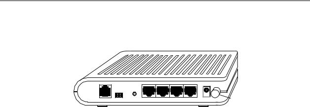
Rear Panel
RESET |
|
|
LINE CONSOLE DEFAULT LAN 1 LAN 2 LAN 3 LAN 4 |
POWER |
Power |
Switch |
05-17711
Figure 1-2. Back Panel
The rear panel contains the ports for the router's data and power connections.
Table 1-2. Rear Panel Labels and Connectors
Label |
Function |
|
|
LINE |
Connects to your ADSL line |
|
|
LAN 1–4 |
Connects the router to Ethernet devices on your LAN, |
|
such as your PC's Ethernet port, or the uplink port on a |
|
hub or switch |
|
|
RESET/DEFAULT |
To reset the router to its default settings |
|
|
POWER |
Connects to the supplied power adapter |
|
|
1-4 |
September 2005 |
6212-A2-GB23-00 |

Hardware Installation and
PC Setup
2
Overview
This chapter provides basic instructions for connecting the router to a computer or a LAN and to the Internet using DSL. The first part provides instructions to set up the hardware, and the second part describes how to prepare your PC for use with the router.
It is assumed that you have already subscribed to DSL service with your Internet service provider (ISP).
6212-A2-GB23-00 |
September 2005 |
2-1 |

2. Hardware Installation and PC Setup
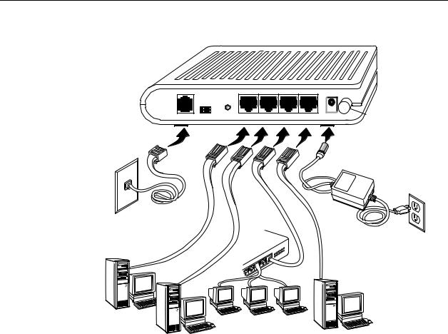
Connecting the Hardware
Shut down your PC and any other equipment before connecting it to the router. To connect your router:
 Procedure
1.Verify that the router’s power switch is in the Off (outward) position. Verify that any PCs and other LAN devices you will attach (such as hubs or switches) are turned off.
2.Use the provided modular phone cable to connect the LINE jack of the router to your RJ11 wall jack.
3.Use the provided Ethernet cable to connect your computer to the router. Attach one end of the Ethernet cable to one of the LAN ports on the back of the router and connect the other end to the Ethernet port or Network Interface Card (NIC) in your PC.
Connect any other PCs, hubs, and switches to the remaining LAN ports. Either a crossover or a straight-through Ethernet cable can be used: the router determines the type of signal required.
4.Connect the cylindrical power plug into the POWER connector on the back of the device. Next:
—If you have a wall-mount adapter, plug the AC adapter into a wall outlet or a power strip.
—If you have a table-top adapter, use the AC power cord to connect the adapter to a wall outlet or power strip.
The supplied power adapter may look different than the one illustrated here.
2-2 |
September 2005 |
6212-A2-GB23-00 |
2. Hardware Installation and PC Setup
RESET |
|
|
LINE CONSOLE DEFAULT LAN 1 LAN 2 LAN 3 LAN 4 |
POWER |
Power |
Switch |
05-17712
Figure 2-1. Hardware Installation
5.Turn on your PC and any other LAN devices, such as hubs or switches.
6.Turn on the router using its power switch.
7.Verify that the router's LEDs are illuminated as shown in Table 2-1.
Table 2-1. LED Indicators
This LED . . . |
Should be: |
|
|
POWER |
Solid green to indicate that the device is turned on. If this light is not |
|
on, check if the power adapter is attached to the router and plugged |
|
into an AC power source. |
|
|
STATUS |
Solid green to indicate that the router can communicate with your ISP |
|
via ADSL, or flashing when the router is trying to connect to your ISP. |
|
|
ACTIVITY |
Flashing when the device is sending or receiving data over the ADSL |
|
connection. |
|
|
LAN |
Solid green to indicate that the device can communicate with your PC |
|
via Ethernet, or flashing when the router is sending or receiving data |
|
over Ethernet. |
|
|
If the LEDs are illuminated as expected, the router is working properly.
6212-A2-GB23-00 |
September 2005 |
2-3 |
2. Hardware Installation and PC Setup
Configuring Your Computer
Before you can access the router over the LAN you have to configure your PC's TCP/IP address to be 192.168.1.x (where x is any number between 3 and 254), with a subnet mask of 255.255.255.0. Your router's default IP address is 192.168.1.1.
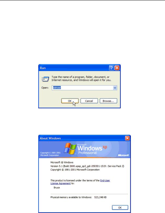
If you know the version of Windows that you use, go to the appropriate section below to learn how to set the IP address of your PC. To determine the version of Windows running on your PC, click on the Windows Start button, then click on Run... in the Start menu. Type winver in the Open selection box and click on OK.
Figure 2-2. Windows Run Dialog
The Windows version is displayed.
Figure 2-3. Windows Version
2-4 |
September 2005 |
6212-A2-GB23-00 |
2. Hardware Installation and PC Setup
Windows XP
1.In the Windows task bar, click on the Start button, and then click on Control Panel.
2.Double-click on the Network Connections icon.
3.In the LAN or High-Speed Internet window, right-click on the icon corresponding to your network interface card (NIC), and select Properties. (Often this icon is labeled Local Area Connection). The Local Area Connection dialog box displays with a list of currently installed network items.
4.Ensure that the check box to the left of the item labeled Internet Protocol (TCP/IP) is checked, and click on Properties.
Figure 2-4. Network Connections (Windows XP)
6212-A2-GB23-00 |
September 2005 |
2-5 |

2. Hardware Installation and PC Setup
Figure 2-5. Local Area Connection Properties (Windows XP)
5.In the Internet Protocol (TCP/IP) Properties dialog box, click on the radio button labeled Use the following IP address. Type an address between 192.168.1.3 and 192.168.1.254 in the IP Address field (192.168.1.20 is shown here as an example) and 255.255.255.0 in the Subnet Mask field.
Figure 2-6. TCP/IP Properties (Windows XP)
6. Click on OK twice to confirm your changes, and close the Control Panel.
2-6 |
September 2005 |
6212-A2-GB23-00 |

2. Hardware Installation and PC Setup
Windows 2000
1.In the Windows task bar, click on the Start button, point to Settings, and then click on Control Panel.
2.Double-click on the Network and Dial-up Connections icon.
3.In the Network and Dial-up Connections window, right-click on the Local Area Connection icon, and then select Properties.
The Local Area Connection Properties dialog box display a list of currently installed network components. If the list includes Internet Protocol (TCP/IP), the protocol has already been enabled; skip to Step 10.
4.If Internet Protocol (TCP/IP) does not appear as an installed component, click on Install.
5.In the Select Network Component Type dialog box, select Protocol, and then click on Add.
6.Select Internet Protocol (TCP/IP) in the Network Protocols list, and then click on OK.
You may be prompted to install files from your Windows 2000 installation CD or other medium. Follow the instructions to install the files.
7.If prompted, click on OK to restart your computer with the new settings.
8.After restarting your PC, double-click on the Network and Dial-up Connections icon in the Control Panel.
9.In Network and Dial-up Connections window, right-click on the Local Area Connection icon, and then select Properties.
10.In the Local Area Connection Properties dialog box, select Internet Protocol (TCP/IP), and then click on Properties.
11.In the Internet Protocol (TCP/IP) Properties dialog box, click on the radio button labeled Use the following IP address. Type an address between 192.168.1.3 and 192.168.1.254 in the IP Address field and 255.255.255.0 in the Subnet Mask field.
12.Click on OK twice to confirm and save your changes, and then close the Control Panel.
Windows ME
1.In the Windows task bar, click on the Start button, point to Settings, and then click on Control Panel.
2.Double-click on the Network and Dial-up Connections icon.
3.In the Network and Dial-up Connections window, right-click on the Network icon, and then select Properties.
The Network Properties dialog box displays a list of currently installed network components. If the list includes Internet Protocol (TCP/IP), the protocol has already been enabled; skip to Step 11.
6212-A2-GB23-00 |
September 2005 |
2-7 |

2.Hardware Installation and PC Setup
4.If Internet Protocol (TCP/IP) does not appear as an installed component, click on Add.
5.In the Select Network Component Type dialog box, select Protocol, and then click on Add.
6.Select Microsoft in the Manufacturers box.
7.Select Internet Protocol (TCP/IP) in the Network Protocols list, and then click on OK.
You may be prompted to install files from your Windows Me installation CD or other media. Follow the instructions to install the files.
8.If prompted, click on OK to restart your computer with the new settings.
9.After restarting your PC, double-click on the Network and Dial-up Connections icon in the Control Panel.
10.In Network and Dial-up Connections window, right-click on the Network icon, and then select Properties.
11.In the Network Properties dialog box, select TCP/IP, and then click on Properties.
12.In the TCP/IP Settings dialog box, click on the radio button labeled Use the following IP address. Type an address between 192.168.1.3 and 192.168.1.254 in the IP Address field and 255.255.255.0 in the Subnet Mask field.
13.Click on OK twice to confirm and save your changes, and then close the Control Panel.
Windows 95 and Windows 98
1.In the Windows task bar, click on the Start button, point to Settings, and then click on Control Panel.
2.Double-click on the Network icon.
The Network dialog box displays a list of currently installed network components. If the list includes TCP/IP, the protocol has already been enabled. Skip to step 9.
3.If TCP/IP does not appear as an installed component, click on Add. The Select Network Component Type dialog box appears.
4.Select Protocol, and then click on Add.
The Select Network Protocol dialog box appears.
5.Click on Microsoft in the Manufacturers list box, and then click on TCP/IP in the Network Protocols list box.
6.Click on OK to return to the Network dialog box, and then click on OK again.
You may be prompted to install files from your Windows 95/98 installation CD. Follow the instructions to install the files.
7.Click on OK to restart the PC and complete the TCP/IP installation.
2-8 |
September 2005 |
6212-A2-GB23-00 |

2. Hardware Installation and PC Setup
8.After restarting your PC, open the Control Panel window, and then click on the Network icon.
9.Select the network component labeled TCP/IP, and then click on Properties.
If you have multiple TCP/IP listings, select the listing associated with your network card or adapter.
10.In the TCP/IP Properties dialog box, click on the IP Address tab.
11.Click in the radio button labeled Use the following IP address. Type an address between 192.168.1.3 and 192.168.1.254 in the IP Address field and 255.255.255.0 in the Subnet Mask field.
12.Click on OK twice to confirm and save your changes. You will be prompted to restart Windows. Click on Yes.
Windows NT 4.0
1.In the Windows NT task bar, click on the Start button, point to Settings, and then click on Control Panel.
2.In the Control Panel window, double click on the Network icon.
3.In the Network dialog box, click on the Protocols tab.
The Protocols tab displays a list of currently installed network protocols. If the list includes TCP/IP, the protocol has already been enabled. Skip to Step 9.
4.If TCP/IP does not appear as an installed component, click on Add.
5.In the Select Network Protocol dialog box, select TCP/IP, and then click on OK.
You may be prompted to install files from your Windows NT installation CD or other medium. Follow the instructions to install the files.
After all files are installed, a window appears to inform you that a TCP/IP service called DHCP can be set up to dynamically assign IP information.
6.Click on Yes to continue, and then click on OK, if prompted, to restart your computer.
7.After restarting your PC, open the Control Panel window, and then double-click on the Network icon.
8.In the Network dialog box, click on the Protocols tab.
9.In the Protocols tab, select TCP/IP, and then click on Properties.
10.In the Microsoft TCP/IP Properties dialog box, click on the radio button labeled Use the following IP address. Type an address between 192.168.1.3 and 192.168.1.254 in the IP Address field and 255.255.255.0 in the Subnet Mask field.
11.Click on OK twice to confirm and save your changes, and then close the Control Panel.
6212-A2-GB23-00 |
September 2005 |
2-9 |
2. Hardware Installation and PC Setup
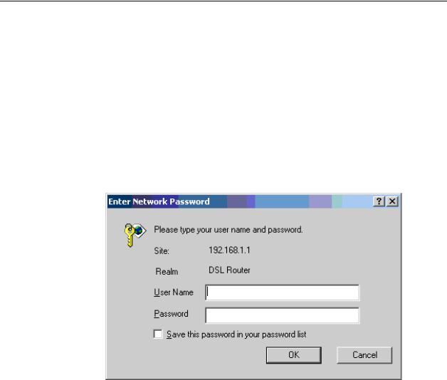
Logging in to Your Router
This section shows how to connect to the router's web interface, configure settings, and observe some statistics of your Internet connection.
1.Open your Web browser, and type the following URL in the address/location box, and press Enter:
http://192.168.1.1
This is the default IP address for the LAN port on the router.
A login screen appears.
Figure 2-7. Login Screen
If you have problem connecting to the router, verify that your PC is properly configured within the subnet of the router's default IP address 192.168.1.1. Setup is described in Configuring Your Computer on page 2-4.
2.Enter your user name and password, and then click on OK to display the home page of the router's web interface. There are two default user name and password combinations:
Table 2-2. |
Default User Names and Passwords |
||
|
|
|
|
User Name |
|
Password |
Capability |
|
|
|
|
user |
|
user |
Can display device status, but cannot change or save |
|
|
|
configuration options. |
|
|
|
|
admin |
|
admin |
Can perform all functions. |
|
|
|
|
You can change the passwords at any time.
2-10 |
September 2005 |
6212-A2-GB23-00 |
Loading...