


889
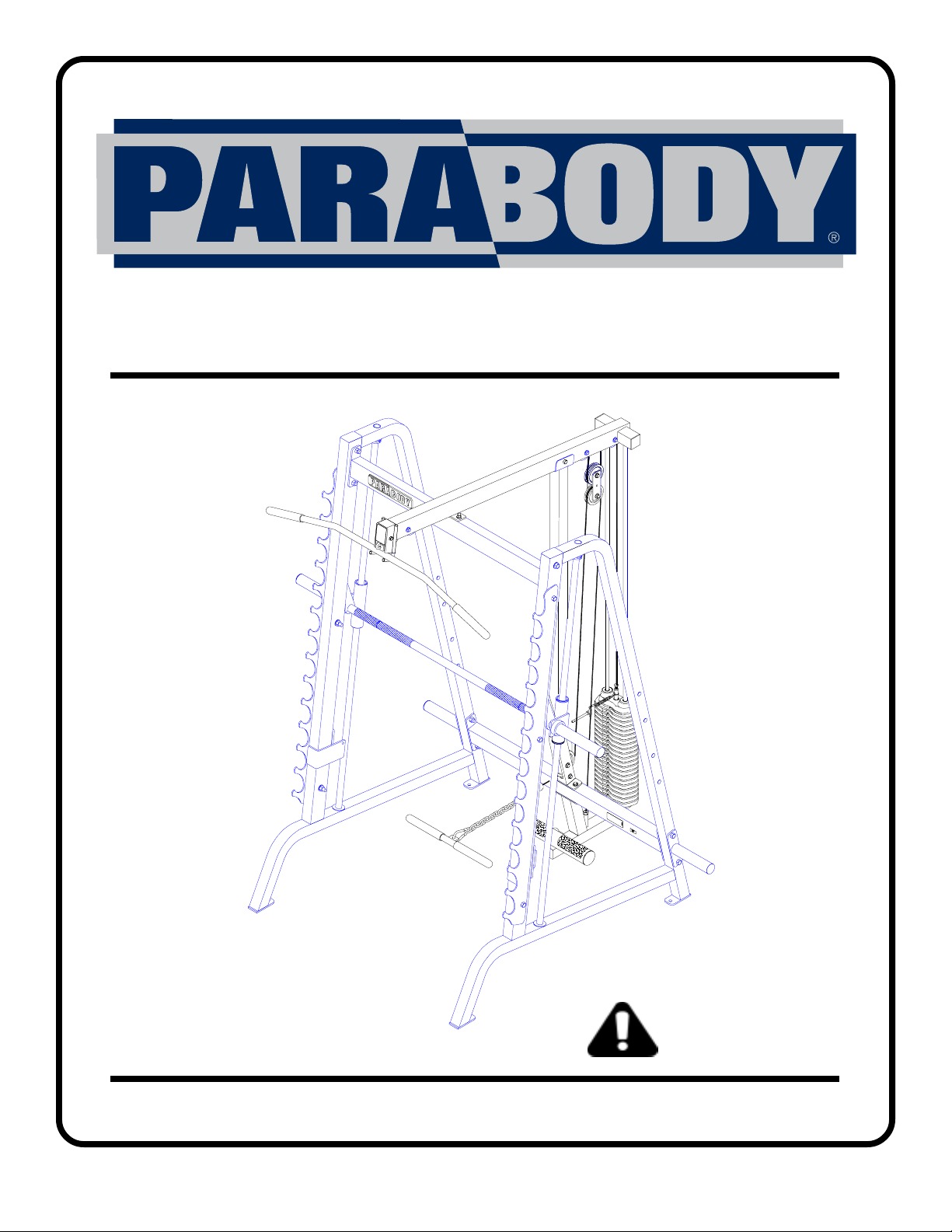
889 WEIGHT STACK OPTION
CLASS H
PART # 7305301
REV . A
USER’S GUIDE
1
WARNING:
Read and follow all directions
for each step to insure proper
assembly of this product.
Version: 889108
Revision: 06/19/02
j
TABLE OF CONTENTS
Safety Statement.............2
General Notes..................3
Tools Required................3
Parts List.........................4
Assembly Instructions......4-13
General Maintenance........14
W arranty Statement..........15
Product Services..............16
Insert-Registration Card
IMPORTANT SAFETY INFORMATION
THERE IS A RISK ASSUMED BY INDIVIDUALS WHO USE THIS TYPE OF
EQUIPMENT. TO MINIMIZE RISK FOLLOW THESE RULES!
1. Before using, read all the warnings and instructions
on the use of this machine. Use only for intended
exercise. DO NOT modify the machine.
2. Obtain a medical exam before beginning any
exercise program.
3. Keep body and clothing free of all moving objects.
4. Inspect the machine before use. DO NOT use it if it
appears damaged. DO NOT attempt to fix a broken or
ammed machine. Notify your authorized ParaBody
dealer before use and have repairs made by an
authorized service technician.
6. Never pin the weights or prop plate into an elevated
position. DO NOT use the machine if found in this
condition. DO NOT attempt to fix. Notify your
authorized ParaBody dealer.
7. Inspect cables and their connections before using
machine. Pay particular attention to the cable ends.
DO NOT attempt to fix. Notify your authorized
ParaBody dealer before use and have repairs made by
an authorized service technician.
8. Make sure all spring loaded pull pins are fully
engaged in the adjustment position and fully tighten
thumbscrew before use.
5. Be certain that weight pin is completely inserted.
Use only the pin provided by the manufacturer. If
unsure, call your authorized ParaBody dealer.
9. Children must not be allowed near this machine.
Supervise teenagers.
.
NOTE: In a continual effort to improve our products, specifications are subject to change
2001 Life Fitness, a division of Brunswick Corporation. All rights reserved.
©
ParaBody is a trademark of Brunswick Corporation
www.parabody.com
2
IMPORTANT NOTES
Please note:
* Thank you for purchasing the ParaBody 889 Weight Stack Option. Please read these
instructions thoroughly and keep them for future reference. This product must be assembled
on a flat, level surface to assure its proper function.
* This product must be assembled on a flat, level surface to assure its proper function. DO NOT
securely tighten any frame connections until the entire frame has been assembled, unless
otherwise stated.
T ools Required for Assembly
* 3/4” wrench
* 9/16” wrench
* Ratchet with 3/4” and 9/16” sockets
* 5/32” Allen wrench
* Adjustable wrench
* T ape measure
Bolt Length Ruler
NOTE: BOL T LENGTH IS MEASURED FROM THE UNDERSIDE OF THE HEAD OF THE BOLT.
BOLT LENGTH
BOL T LENGTH RULER:
1/2 1/2 1/2 1/2 1/2 1/2
0
1
2
345
3
6
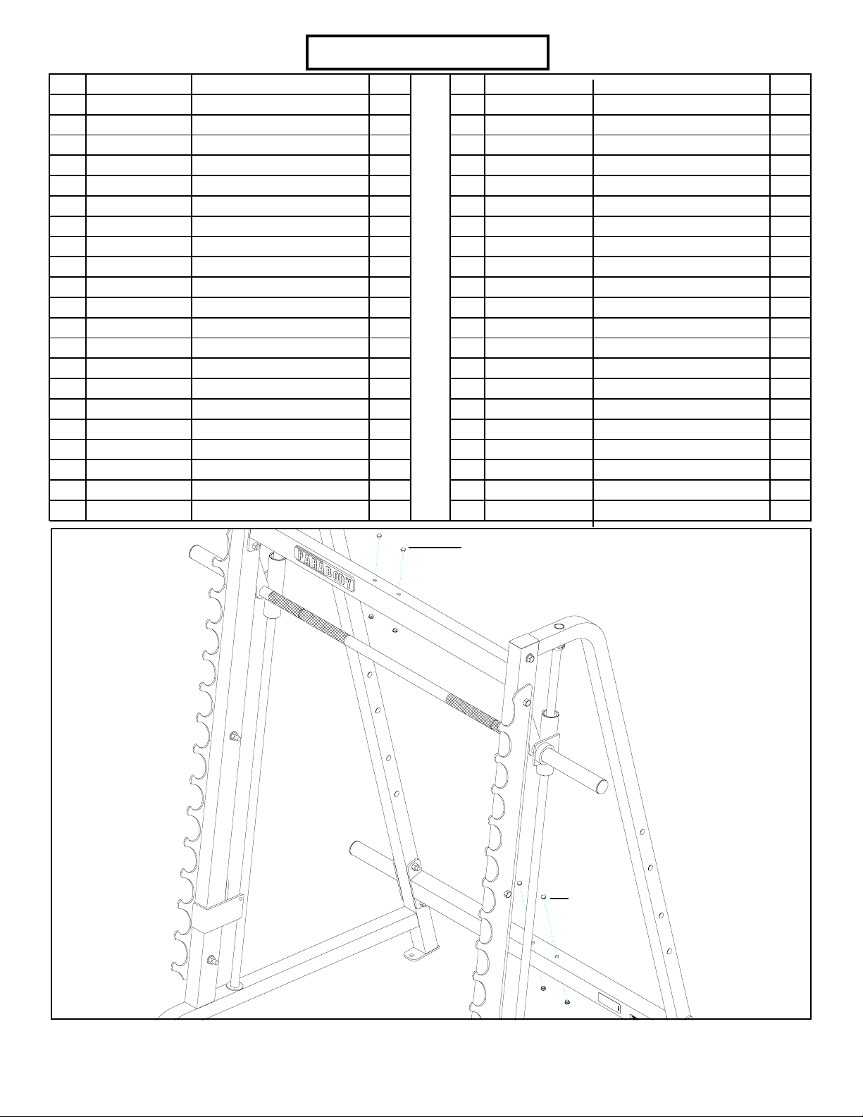
PARTS LIST
KEY
1
2
3
4
5
6
7
8
9
10
11
12
13
14
15
16
17
18
19
20
21
PART #
LEA6814309
LEA6800610
LEA6814009
LEA6813709
LEA6801110
LEA6816501
LEA6274410
LEA6725310
LEA3116201
LEA3116101
LEA6832801
LEA6671002
LEA6692601
LEA3103102
LEA3103302
LEA6405201
LEA6972201
LEA6177001
LEA3119301
LEA6236701
LEA6412001
DESCRIPTION
UPRIGHT
ADJ FOOT SUPPOR T
ST ACK BASE
TOP BOOM
LA T BAR SUPPOR T
76” GUIDE ROD
LOW ROW BAR
LA T BAR
3-1/2” PULLEY
4-1/2” PULLEY
124” CABLE
115-3/4” CABLE
3 X 2” END CAP
1 X 8” GRIP
13/16” SHAFT COLLAR
2” SQ. END CAP
WEIGHT ST ACK SELCT PIN
2-1/2 X 5-1/2” NON-SKID STP
2-1/2” ROUND END CAP
1-3/4” SQ. END CAP
SPRING PIN ASSEMBL Y
QTY
1
1
1
1
1
2
1
1
5
1
1
1
2
4
2
4
1
2
2
1
1
KEY
22
23
24
25
26
27
28
29
30
31
32
33
34
35
36
37
38
PART #
LEA3203301
LEA6542402
LEA6416601
LEA7292501
LEA3108002
LEA6595201
LEA7308601
LEA3235502
LEA3114403
LEA3114702
LEA3235211
LEA6480301
LEA3103801
LEA3235208
LEA7292801
LEA6075906
LEA3235216
DESCRIPTION
VINYL CAP
3/16 X 1-3/4 X 5-1/4” PL TE
3/4 X 1-1/2” GLIDE
WEIGHT PLA TE
WEIGHT ST ACK CUSHION
GUIDE ROD BUSHING
WEIGHT ST ACK LBLS (1-26)
3/8” LOW HT LOCK NUT
3/8” W ASHER
3/8” LOCK NUT
3/8 X 2-3/4” BOL T
3/8” FLANGE SP ACER
5/16” SNAP HOOK
3/8 X 2” BOL T
HEAD PLA TE ASSEMBL Y
12 LINK CHAIN
3/8 X 4” BOL T
QTY
2
2
1
20
2
2
1
3
14
10
7
8
3
2
1
1
4
7/16” CAP PLUG
7/16” CAP
PLUG
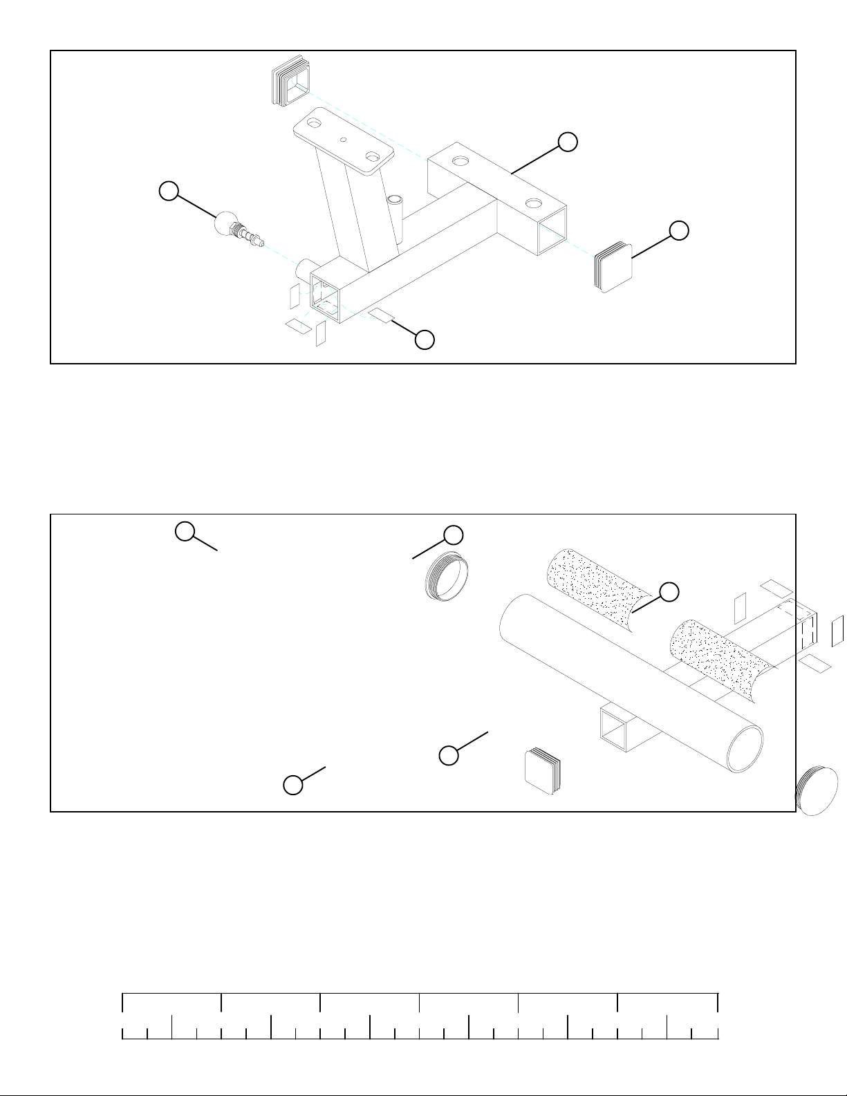
FIGURE 1
STEP 1:
• Remove four 7/16” CAP PLUGS from the UPPER & LOWER CROSS SUPPOR TS on the 888 SMITH MACHINE as shown in FIGURE 1.
4
3
21
16
FIGURE 2
24
STEP 2:
• Insert two 2” END CAP (16) into the ends of the ST ACK BASE (3) as shown in FIGURE 2.
• Attach four 3/4 X 1-1/2” GLIDES (24) to the inside of the tube on the STACK BASE (3) as shown in FIGURE 2 using the
following steps:
• Thoroughly clean all surfaces where the 3/4 X 1-1/2” GLIDES (24) are to be attached.
• Remove the 3/4 X 1-1/2” GLIDES (24) from the paper backing and firmly apply them to all shown surfaces.
• SECUREL Y assemble one SPRING PIN ASSEMBLY (21) to the spring pin barrel on the STACK BASE (3). See FIGURE 2.
19
18
24
2
20
FIGURE 3
STEP 3:
• Insert two 2-1/2” ROUND END CAPS (19) into the ends of the ADJ. FOOT SUPPORT (2) as shown in FIGURE 3.
• Insert one 1-3/4” END CAP (20) into the end of the ADJ. FOOT SUPPOR T (2) as shown in FIGURE 3.
• Apply two 2-1/2 X 5-1/2” NON-SKID STRIPS (18) to the ADJ. FOOT SUPPORT (2) as shown in FIGURE 3.
• Attach four 3/4 X 1-1/2” GLIDES (24) to the outside of the ADJ FOOT SUPPORT (2) as shown in FIGURE 3 using the
following steps:
• Thoroughly clean all surfaces where the 3/4 X 1-1/2” GLIDES (24) are to be attached.
• Remove the 3/4 X 1-1/2” GLIDES (24) from the paper backing and firmly apply them to all shown surfaces.
1/2 1/2 1/2 1/2 1/2 1/2
0
1
2
345
5
6
 Loading...