


777 GYM SYSTEM
WARNING:
Read and follow all directions for each step to insure proper assembly of this product.
USER’S GUIDE
CLASS H |
1 |
Version: 777102 |
PART # 7148201 |
|
Revision: 07/26/01 |
REV.A |
|
|

TABLE OF CONTENTS
Safety Statement |
.............2 |
General Notes.................. |
3 |
Tools Required................ |
3 |
Gym Layout..................... |
4 |
Parts list.......................... |
5 |
Assembly Instructions..... |
6-25 |
General Maintenance....... |
26 |
Warranty Statement.......... |
27 |
Product Services.............. |
28 |
Insert-Registration Card |
|
IMPORTANT SAFETY INFORMATION
THERE IS A RISK ASSUMED BY INDIVIDUALS WHO USE THIS TYPE OF
EQUIPMENT. TO MINIMIZE RISK FOLLOW THESE RULES!
1.Before using, read all the warnings and instructions on the use of this machine. Use only for intended exercise. DO NOT modify the machine.
2.Obtain a medical exam before beginning any exercise program.
3.Keep body and clothing free of all moving objects.
4.Inspect the machine before use. DO NOT use it if it appears damaged. DO NOT attempt to fix a broken or
jammed machine. Notify your authorized ParaBody dealer before use and have repairs made by an authorized service technician.
5. Be certain that weight pin is completely inserted. Use only the pin provided by the manufacturer. If unsure, call your authorized ParaBody dealer.
6. Never pin the weights or prop plate into an elevated position. DO NOT use the machine if found in this condition. DO NOT attempt to fix. Notify your authorized ParaBody dealer.
7. Inspect cables and their connections before using machine. Pay particular attention to the cable ends. DO NOT attempt to fix. Notify your authorized ParaBody dealer before use and have repairs made by an authorized service technician.
8.Make sure all spring loaded pull pins are fully engaged in the adjustment position and fully tighten thumbscrew before use.
9.Children must not be allowed near this machine. Supervise teenagers.
.
NOTE: In a continual effort to improve our products, specifications are subject to change © 2001 Life Fitness, a division of Brunswick Corporation. All rights reserved. ParaBody is a trademark of Brunswick Corporation
www.parabody.com
2
IMPORTANT NOTES
Please note:
*Thank you for purchasing the ParaBody 777 Gym System. Please read these instructions thoroughly and keep them for future reference.
*This product must be assembled on a flat, level surface to assure its proper function.
*Do not securely tighten any frame connections until the entire frame have been assembled unless otherwise specified.
Tools Required for Assembly
*Rubber mallet or hammer
*3/4” wrench
*9/16” wrench
*Ratchet with 3/4” and 9/16” sockets
*5/32” Allen wrench
*Adjustable wrench
*Tape measure
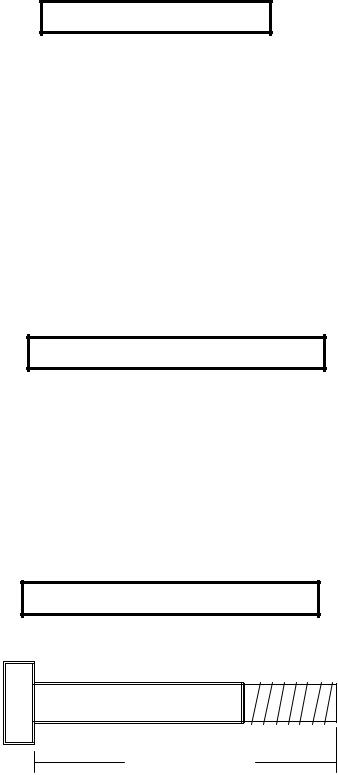
Bolt Length Ruler
NOTE: BOLT LENGTH IS MEASURED FROM THE UNDERSIDE OF THE HEAD OFTHE BOLT.
BOLT LENGTH
BOLT LENGTH RULER:
|
1/2 |
|
1/2 |
|
1/2 |
|
1/2 |
|
1/2 |
|
|
1/2 |
|
|||||||||||
0 |
|
|
1 |
|
|
2 |
|
|
3 |
|
|
4 |
|
|
5 |
|
6 |
|||||||
|
|
|
|
|
|
|
|
|
|
|
|
|
|
|
|
|
|
|
|
|
|
|
|
|
3
1’ |
2’ |
3’ |
4’ |
5’ |
6’ |
7’ |
8’ |
9’ |
1’
2’
3’
4’
5’
6’
7’
8’
9’
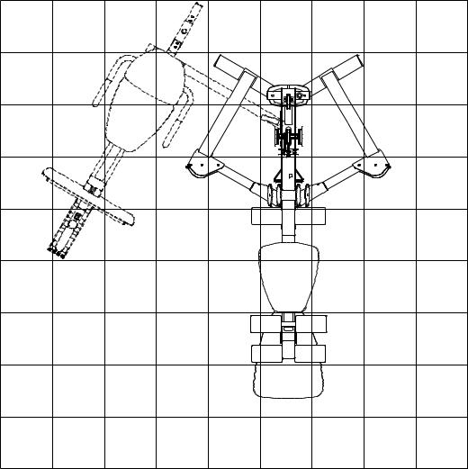
1 Square = 1’ X 1’
Minimum Required Usable Space
Length |
= 90 inches (229 cm) 7’ 6” |
Width |
= 103 inches (262 cm) 8’ 7” |
Height |
= 84 inches (213.5 cm) 7” |
Dimensions Including Leg Press (optional)
Length |
= 102 inches (259 cm) 8’ 6” |
Width |
= 130 inches (330 cm) 10’ 10” |
4

PARTS LIST
KEY |
PAR T # |
DESCRIPTION |
QTY |
1 |
70077 |
BASE |
1 |
2 |
70076 |
UPRIGHT |
1 |
3 |
70058 |
SEATADJUST |
1 |
4 |
70014 |
RIGHTARM SUPPORT |
1 |
5 |
70015 |
LEFTARM SUPPORT |
1 |
6 |
70017 |
RIGHT ARM |
1 |
7 |
70019 |
LEFTARM |
1 |
8 |
70056 |
LEG PEDESTAL |
1 |
9 |
70067 |
PULLEY BRACKET |
1 |
10 |
69408 |
PULLEY PLATE |
2 |
11 |
69885 |
BASE PLATE |
2 |
12 |
69954 |
V-PULLEY PLATE |
2 |
13 |
69957 |
BOOM PULLEY PLATE |
2 |
14 |
71552 |
RIGHT BOOM PLATE |
1 |
15 |
71553 |
LEFT BOOM PLATE |
1 |
16 |
69947 |
PAD |
2 |
17 |
6194601 |
ROLLER PAD |
6 |
18 |
6816501 |
76” GUIDE ROD |
2 |
19 |
7016902 |
14-1/2” SEWN HANDLE |
2 |
20 |
7016901 |
7-1/2” SEWN HANDLE |
2 |
21 |
6939202 |
WEIGHT PLATE |
15 |
22 |
6382301 |
WEIGHT PLATE BUSHING 10 CT |
3 |
23 |
69537 |
HEAD PLATE |
1 |
24 |
3221702 |
E-RING |
1 |
25 |
6978101 |
WEIGHT STACK LABEL |
1 |
26 |
7095701 |
WEIGHT PLATE SHAFT |
1 |
27 |
6972201 |
WEIGHT STACK PIN |
1 |
28 |
3108002 |
WEIGHT STACK CUSHION |
2 |
29 |
7155701 |
WEIGHT STACK CABLE |
1 |
30 |
6987901 |
LEG CABLE |
1 |
31 |
6988001 |
ARM CABLE |
1 |
32 |
6988101 |
BOOM CABLE |
1 |
33 |
7012102 |
WEIGHT STACK SPACER |
2 |
34 |
3102503 |
3/4” FLAT WASHER |
2 |
35 |
6409101 |
ANKLE STRAP |
1 |
|
|
|
|
KEY |
PART # |
DESCRIPTION |
QTY |
36 |
3103302 |
SHAFT COLLAR |
2 |
37 |
3116201 |
3-1/2” PULLEY |
14 |
38 |
3116101 |
4-1/2” PULLEY |
3 |
39 |
6993701 |
4-1/2” V-GROOVE PULLEY |
4 |
40 |
6412001 |
SPRING PIN ASSEMBLY |
1 |
41 |
3103801 |
SNAP LINK |
6 |
42 |
6416601 |
PARAGLIDE (QTY 8) |
1 |
43 |
6145801 |
3 PRONG KNOB |
1 |
44 |
3105401 |
STARLOCK |
6 |
45 |
3108901 |
PLASTIC WASHER |
2 |
46 |
6866801 |
1/2” RH WASHER |
2 |
47 |
6866601 |
RH CAP |
2 |
48 |
6480301 |
3/8” X 9/16” FLANGE SPACER |
2 |
49 |
6480302 |
3/8 X 1-1/16” FLANGE SPACER |
2 |
50 |
6122702 |
3/8 X 1/2” SPACER |
6 |
51 |
6122701 |
3/8” X 1” SPACER |
11 |
52 |
6549301 |
3/4 X 17” TUBE |
3 |
53 |
3102924 |
3/8 X 1-3/4” BOLT |
4 |
54 |
3102807 |
3/8 LOW HEIGHT LOCK NUT |
2 |
55 |
3102922 |
3/8 X 2-3/4” BOLT |
16 |
56 |
3221902 |
2” NYLON SPACER |
4 |
57 |
3102905 |
3/8 X 3-3/4” BOLT |
17 |
58 |
3102917 |
1/2 X 4” BOLT |
1 |
59 |
6075906 |
12 LINK CHAIN |
1 |
60 |
3102906 |
3/8 X 4” BOLT |
2 |
61 |
3102930 |
3/8 X 7” BOLT |
1 |
62 |
3102804 |
1/2” LOW HEIGHT LOCK NUT |
1 |
63 |
3102802 |
3/8” LOCK NUT |
36 |
64 |
3102501 |
3/8” FLAT WASHER |
14 |
65 |
6020601 |
1/2” FLANGE BEARING |
2 |
66 |
70718 |
FOOT PLATE |
1 |
67 |
3102904 |
3/8 X 3” BOLT |
2 |
68 |
3102955 |
3/8 X 4-1/4” BOLT |
2 |
69 |
3102514 |
3/8” SAE WASHER |
4 |
70 |
71185 |
GUIDE BRACKET |
1 |
71 |
7122101 |
GUIDE CABLE |
2 |
|
|
|
|
|
1/2 |
|
|
1/2 |
|
1/2 |
|
1/2 |
|
1/2 |
|
|
1/2 |
0 |
1 |
2 |
3 |
|
4 |
5 |
6 |
||||||
53
|
2 |
|
57 3/8 X 3-3/4” |
|
|
|
|
1 |
3/8 X 3” |
67 |
|
|
48 |
11 |
|
|
|
|
|
63 |
66 |
63 |
|
|
|
|
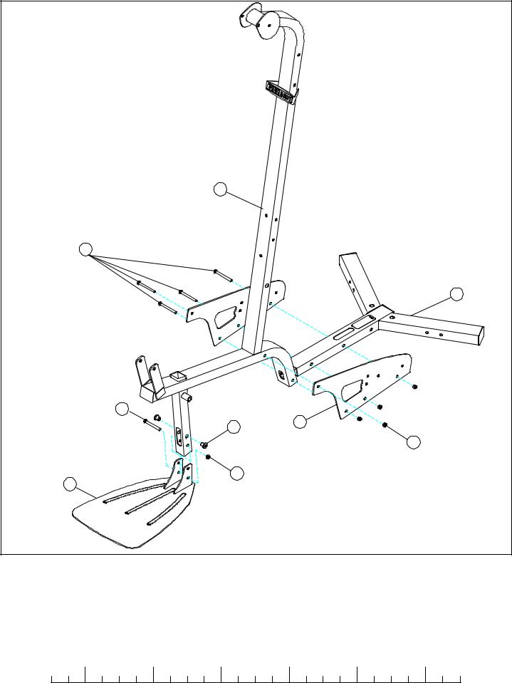
FIGURE 1 |
|
|
STEP 1:
•LOOSELY assemble two BASE PLATES (11) to the BASE (1) and the UPRIGHT (2) using four 3/8 X 3-3/4” BOLTS (57) and four 3/8” LOCK NUTS (63). See FIGURE 1.
•Insert two two 3/8 X 9/16” FLANGE SPACERS (48) into the upper hole of the FRAME (2) as shown.
•LOOSELY assemble the FOOTPLATE (66) to the FRAME (2) using one 3/8 X 3” BOLT (67) and one 3/8” LOCK NUT (63) as shown in FIGURE 1.
|
1/2 |
|
1/2 |
|
1/2 |
|
1/2 |
|
1/2 |
|
|
1/2 |
0 |
1 |
2 |
3 |
4 |
5 |
6 |
||||||
6
22
21
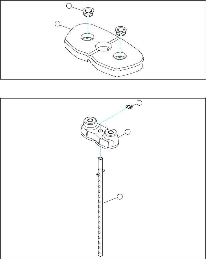
FIGURE 2
STEP 2:
• Insert two WEIGHT PLATE BUSHINGS (22) into each of the fifteen WEIGHT PLATES (21) as shown in FIGURE 2.
24
23
26
FIGURE 3
STEP 3:
•Slide the WEIGHT PLATE SHAFT (26) thru the hole in the HEAD PLATE(23), and lock in place using one E-RING (24) as shown in FIGURE 3.
7
36
18
23
21
28
34
33

 777 SHROUD
OPTION ONLY!
1
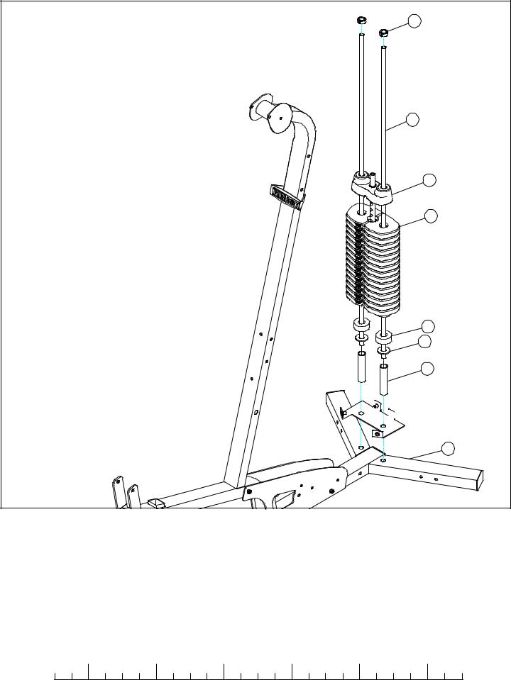
FIGURE 4
STEP 4:
•Insert two GUIDE RODS (18) into the BASE (1) as shown on FIGURE 4. (NOTE: If the 777 SHROUD OPTION was purchased, place the GUIDE RODS (18) through the BOTTOM SHROUD BRACKET (found in SHROUD OPTION box) and into the BASE (1) as shown in FIGURE 4.
•(NOTE: Lubricate GUIDE RODS (18) with silicon or teflon spray available at most hardware stores.)
•Slide two WEIGHT STACK SPACERS (33), two 3/4” FLAT WASHERS (34), and two WEIGHT STACK CUSHIONS (28) down over the GUIDE RODS (18).
•Using EXTREME CARE slide all fifteen WEIGHT PLATES (21) down over the GUIDE RODS (18) on to the WEIGHT STACK CUSHIONS (28). Make sure that the WEIGHT PLATES (21) are all facing as shown.
•Slide the head plate assembly down over the GUIDE RODS (18) onto the weight stack.
•Slide two SHAFT COLLARS (36) over the GUIDE RODS (18) as shown in FIGURE 4.
|
1/2 |
|
1/2 |
|
1/2 |
|
1/2 |
|
1/2 |
|
|
1/2 |
0 |
1 |
2 |
3 |
4 |
5 |
6 |
||||||
8
14
36
TIGHTEN!
3/8 X 3-3/4” 57 |
15 |
18 |
|
2 |
63 |
|
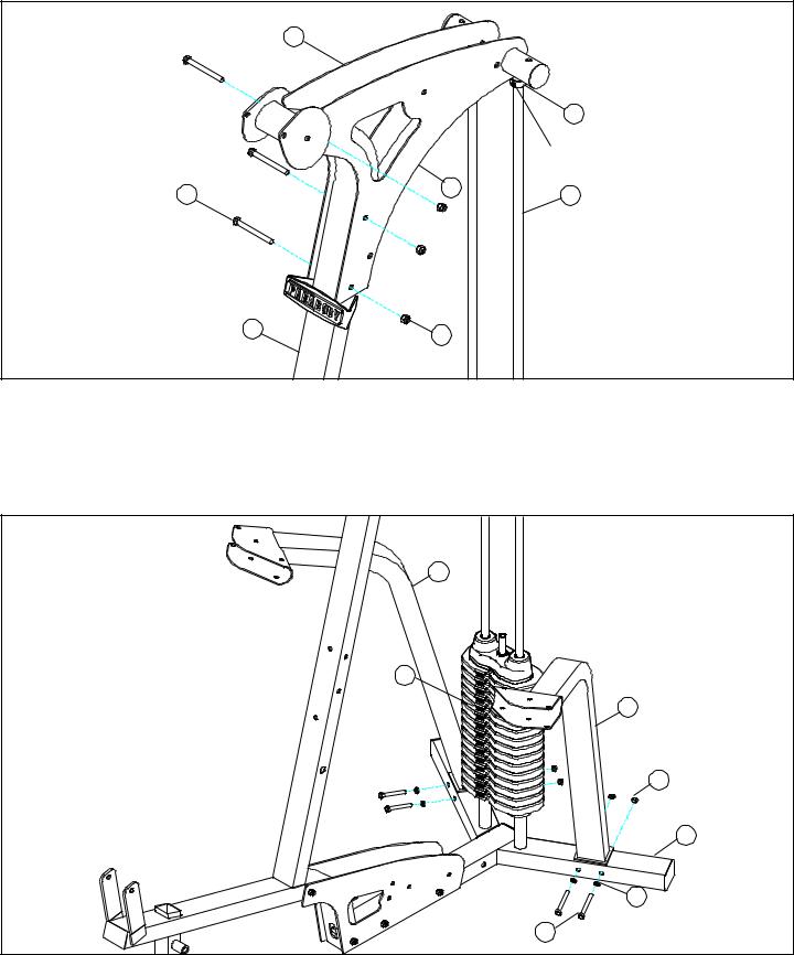
FIGURE 5
STEP 5:
•Swing the GUIDE RODS (18) into the guide rod bushings in each of the RIGHT and LEFT BOOM PLATES (14 & 15) as shown in FIGURE 5.
•LOOSELY assemble the RIGHT and LEFT BOOM PLATES (14 & 15) to the UPRIGHT (2) using three 3/8 X 3-3/4” BOLTS (57) and three 3/8” LOCK NUTS (63). See FIGURE 5.
•Slide the SHAFT COLLARS (36) to the top of the GUIDE RODS (18) and tighten set screws as shown in FIGURE 5.
FIGURE 6
4
25
5
63
1
64
3/8 X 3-3/4” 57
STEP 6:
•LOOSELY assemble the RIGHT and LEFT ARM SUPPORTS (4 & 5) to the BASE (1) using four 3/8 X 3-3/4” BOLTS (57), four 3/8” FLAT WASHERS (64), and four 3/8” LOCK NUTS (63). See FIGURE 6.
•Apply WEIGHT STACK LABELS (25) to the WEIGHT PLATES (21) as shown in FIGURE 6.
9
 Loading...