


 Loading...
Color CCTV Cameras
Operating Instructions
Model No. WV-CW484 Series
ENGLISH
FRANÇAIS
WV-CW484F is shown above.
Before attempting to connect or operate this product,
please read these instructions carefully and save this manual for future use.
No model number suffix is shown in this manual.
CAUTION
RISK OF ELECTRIC
SHOCK DO NOT OPEN
CAUTION: TO REDUCE THE RISK OF ELECTRIC SHOCK,
DO NOT REMOVE COVER (OR BACK).
NO USER-SERVICEABLE PARTS INSIDE.
REFER SERVICING TO QUALIFIED SERVICE PERSONNEL.
The lightning flash with arrowhead symbol, within an equilateral triangle, is intended to alert the user to the presence of uninsulated "dangerous voltage" within the product's enclosure that may be
SA 1965 of sufficient magnitude to constitute a risk of electric shock to persons.
The exclamation point within an equilateral triangle is intended to alert the user to the presence of important operating and maintenance (servicing) instructions in the literature accompanying the
appliance.
SA 1966
For Canada
This Class A digital apparatus complies with Canadian ICES-003.
For U.S.A
NOTE: This equipment has been tested and found to comply with the limits for a Class A digital device, pursuant to Part 15 of the FCC Rules. These limits are designed to provide reasonable protection against harmful interference when the equipment is operated in a commercial environment. This equipment generates, uses, and can radiate radio frequency energy and, if not installed and used in accordance with the instruction manual, may cause harmful interference to radio communications.
Operation of this equipment in a residential area is likely to cause harmful interference in which case the user will be required to correct the interference at his own expense.
FCC Caution: To assure continued compliance, (example - use only shielded interface cables when connecting to computer or peripheral devices). Any changes or modifications not expressly approved by the party responsible for compliance could void the user’s authority to operate this equipment.
The serial number of this product may be found on the surface of the unit.
You should note the serial number of this unit in the space provided and retain this book as a permanent record of your purchase to aid identification in the event of theft.
Model No.
Serial No.
WARNING:
•This apparatus must be earthed.
•All work related to the installation of this product should be made by qualified service personnel or system installers.
•The connections should comply with local electrical code.
2
Important Safety Instructions
1) |
Read these instructions. |
|
2) |
Keep these instructions. |
|
3) |
Heed all warnings. |
|
4) |
Follow all instructions. |
|
5) |
Clean only with dry cloth. |
|
6) |
Do not block any ventilation openings. Install in accordance with the manufacturer's |
ENGLISH |
|
instructions. |
|
|
|
|
7) |
Do not install near any heat sources such as radiators, heat registers, stoves, or other |
|
|
apparatus (including amplifiers) that produce heat. |
|
8) |
Do not defeat the safety purpose of the polarized or grounding-type plug. A polarized plug |
|
|
has two blades with one wider than the other. A grounding type plug has two blades and a |
|
|
third grounding prong. The wide blade or the third prong are provided for your safety. If the |
|
|
provided plug does not fit into your outlet, consult an electrician for replacement of the |
|
|
obsolete outlet. |
|
9) |
Protect the power cord from being walked on or pinched particularly at plugs, convenience |
|
|
receptacles, and the point where they exit from the apparatus. |
|
10)Only use attachments/accessories specified by the manufacturer.
11)Use only with the cart, stand, tripod, bracket, or table specified by the manufacturer, or sold with the apparatus. When a cart is used, use caution when moving the cart/apparatus combination to avoid injury from tip-over.
S3125A
12) Unplug this apparatus during lightning storms or when unused for long periods of time.
3

Limitation of Liability
THIS PUBLICATION IS PROVIDED "AS IS" WITHOUT WARRANTY OF ANY KIND, EITHER EXPRESS OR IMPLIED, INCLUDING BUT NOT LIMITED TO, THE IMPLIED WARRANTIES OF MERCHANTABILITY, FITNESS FOR ANY PARTICULAR PURPOSE, OR NON-INFRINGEMENT OF THE THIRD PARTY'S RIGHT.
THIS PUBLICATION COULD INCLUDE TECHNICAL INACCURACIES OR TYPOGRAPHICAL ERRORS. CHANGES ARE ADDED TO THE INFORMATION HEREIN, AT ANY TIME, FOR THE IMPROVEMENTS OF THIS PUBLICATION AND/OR THE CORRESPONDING PRODUCT (S).
Disclaimer of Warranty
IN NO EVENT SHALL MATSUSHITA ELECTRIC INDUSTRIAL CO., LTD. BE LIABLE TO ANY PARTY OR ANY PERSON, EXCEPT FOR REPLACEMENT OR REASONABLE MAINTENANCE OF THE PRODUCT, FOR THE CASES, INCLUDING BUT NOT LIMITED TO BELOW:
(1)ANY DAMAGE AND LOSS, INCLUDING WITHOUT LIMITATION, DIRECT OR INDIRECT, SPECIAL, CONSEQUENTIAL OR EXEMPLARY, ARISING OUT OF OR RELATING TO THE PRODUCT;
(2)PERSONAL INJURY OR ANY DAMAGE CAUSED BY INAPPROPRIATE USE OR NEGLIGENT OPERATION OF THE USER;
(3)UNAUTHORIZED DISASSEMBLE, REPAIR OR MODIFICATION OF THE PRODUCT BY THE USER;
(4)INCONVENIENCE OR ANY LOSS ARISING WHEN IMAGES ARE NOT DISPLAYED, DUE TO ANY REASON OR CAUSE INCLUDING ANY FAILURE OR PROBLEM OF THE PRODUCT;
(5)ANY PROBLEM, CONSEQUENTIAL INCONVENIENCE, OR LOSS OR DAMAGE, ARISING OUT OF THE SYSTEM COMBINED BY THE DEVICES OF THIRD PARTY;
(6)ANY CLAIM OR ACTION FOR DAMAGES, BROUGHT BY ANY PERSON OR ORGANIZATION BEING A PHOTOGENIC SUBJECT, DUE TO VIOLATION OF PRIVACY WITH THE RESULT OF THAT SURVEILLANCE-CAMERA'S PICTURE, INCLUDING SAVED DATA, FOR SOME REASON, BECOMES PUBLIC OR IS USED FOR THE PURPOSE OTHER THAN SURVEILLANCE.
4

Preface
Panasonic's WV-CW484 series cameras (WV-CW484F/WV-CW484S/WV-CW484FK/WV- CW484SK) introduce high picture quality by use of Super-Dynamic 1/3 inch CCD and digital signal processing LSIs.
•WV-CW484F: This is a model with x2 varifocal lens. Mounting bracket and ceiling mount bracket are optional.
•WV-CW484S: This is a model with x2 varifocal lens. Mounting bracket is supplied, but ceiling mount bracket are optional.
•WV-CW484FK: Lens, mounting bracket, and ceiling mount bracket are optional.
•WV-CW484SK: Lens is optional. Mounting bracket is supplied, but ceiling mount bracket are optional.
Features
•Super Dynamic 3: 128x with zone-free brightness detection
•High sensitivity: 0.16 lx {0.016 footcandle} at F1.4 in B/W mode, 1.5 lx {0.15 footcandle} at F1.4 in color mode
With the optional Clear Dome Cover WV-CW4C, 0.08 lx {0.008 footcandle} in B/W mode and 0.6 lx {0.06 footcandle} in color mode become available.
•Auto nighttime switching to Black and White Mode
The camera can be configured to switch to the black and white mode automatically under low light conditions for clear images, even at night.
•High resolution: 540 TV lines typical, 520 TV lines minimum
•Sensitivity enhancement: Up to 10x AUTO/32x FIX
•Synchronization: Multiplexed vertical drive (VD2), Line-locked (LL), or Internal (INT)
•Auto-Back-Focus (flange-back (back focal) length adjustment): 1-push adjustment (local/remote), manual adjustment (local/remote), automatic adjustment at BW/CL transition Setup using an optional system controller is also available.
•Light control: ALC
•Miscellaneous: Privacy zone setting, Video motion detection, etc.
5

CONTENTS |
|
Important Safety Instructions ..................................................................................................... |
3 |
Limitation of Liability ................................................................................................................... |
4 |
Disclaimer of Warranty ............................................................................................................... |
4 |
Preface ....................................................................................................................................... |
5 |
Features ..................................................................................................................................... |
5 |
Precautions ................................................................................................................................ |
7 |
Major Operating Controls and Their Functions .......................................................................... |
10 |
Lens Mounting (WV-CW484FK, CW484SK) .............................................................................. |
12 |
Installations ................................................................................................................................ |
13 |
Image Adjustment ...................................................................................................................... |
21 |
Connections ............................................................................................................................... |
23 |
Flange-back (Back Focal) Adjustment for Optional Lenses ....................................................... |
26 |
About Setup Menus .................................................................................................................... |
27 |
Setting Procedures ..................................................................................................................... |
31 |
Troubleshooting ......................................................................................................................... |
45 |
Specifications ............................................................................................................................. |
46 |
Standard Accessories ................................................................................................................ |
47 |
Optional Accessories ................................................................................................................. |
48 |
6

Precautions
This apparatus has no power switch.
Power is supplied from an external 12 V DC/24 V AC power-supply device. Refer to service personnel for how to turn on/off the power.
To keep on using with stable performance
•Parts of this product may deteriorate and it may shorten lifetime of this product when using in locations subject to high temperatures and high humidity. Do not expose the product to direct heat such from a heater.
•Use the appliance at temperature within –10 °C to +50 °C {14 °F to 122 °F} and humidity below 90 %. (When using the appliance without turning the power off)
With the optional Heater Unit WV-CW4H, this apparatus can be used at tempera-
ture within –30 °C to +50 |
°C {–22 °F to |
122 °F} and humidity below |
90 %. |
Do not drop metallic parts through slots.
This could permanently damage the apparatus. Turn the power off immediately and contact qualified service personnel for service.
Do not rub the edges of metal parts with your hand.
Failure to observe this may cause injury.
Do not attempt to disassemble the camera.
To prevent electric shock, do not remove screws or covers.
There are no user-serviceable parts inside. Ask qualified service personnel for servicing.
Handle the camera with care.
Do not abuse the camera. Avoid striking, shaking, etc. The camera could be damaged by improper handling or storage.
Do not touch the dome cover with your bare hands.
A dirty dome cover causes deterioration of picture quality.
Cleaning the camera body
Turn the power off when cleaning the camera. Use a dry cloth to clean the camera. Do not use strong abrasive detergent when cleaning the camera body. When the dirt is hard to remove, use a mild detergent and wipe gently. Then, wipe off the remaining detergent with a dry cloth.
Otherwise, it may cause discoloration. When using a chemical cloth for cleaning, read the caution provided with the chemical cloth product.
Discoloration on the CCD color filter
When continuously shooting a bright light source such as a spotlight, the color filter of the CCD may have deteriorated and it may cause discoloration. Even when changing the fixed shooting direction after continuously shooting a spotlight for a certain period, the discoloration may remain.
7
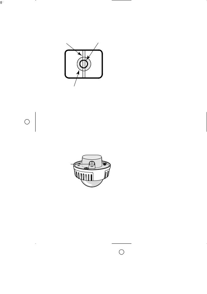
Do not aim the apparatus at strong light sources.
A light source such as a spot light causes a blooming (light bleeding) or a smear (vertical lines).
Smear |
Bright subject |
Blooming
About the dehumidifying device
•The camera has dehumidifying device to keep the inside at low moisture level, preventing condensation and quickly dissipating dew if produced.
•Dew may be produced depending on the conditions of temperature, humidity, winds, and rain, and it may take time to dehumidify.
•Never seal the surfaces of the dehumidifying device.
Dehumidifying device
Turn the circuit breaker off which supplies the camera with the power when abnormal conditions are encountered.
Observe the following for installation.
•This apparatus is designed to be installed under eaves. Install this apparatus under eaves to avoid direct sunlight.
•If this apparatus is installed outdoors without eaves, ensure the same circumstances as being under eaves.
Avoid installing in the following locations.
•Locations where a chemical agent is used such as a swimming pool
•Locations subject to steam and oil smoke such as a kitchen
•Locations near flammable gas or vapor
•Locations where radiation or x-ray emissions are produced
•Locations subject to strong magnetic field or radio waves
•Locations where corrosive gas is produced
•Locations where it may be damaged by briny air such as seashores
•Locations where the temperature is not within –10 °C to +50 °C {14 °F to 122 °F}.
•Locations subject to vibrations (This product is not designed for on-vehicle use.)
Installing place
Contact your dealer for assistance if you are unsure of an appropriate place in your particular environment.
Make sure that the installation area is strong enough to hold the camera, such as a concrete ceiling.
When the installation area is not strong enough, reinforce and strengthen it or use Mounting Bracket (WV-CW484F, WV-CW 484FK: option, WV-CW484S, WV-CW484SK: provided) or Ceiling Mount Bracket. (Refer to p. 48 Optional Accessories.)
Do not install the camera in a humid or dust-laden environment.
Otherwise, lifetime of the internal parts may be shortened.
8

Be sure to remove this apparatus if it is not in use.
Radio interference
When the camera is used near TV/radio antenna, strong electric field or magnetic field (near a motor or a transformer), images may be distorted and noise sound may be produced.
Mounting screws
Only the fixing screws are provided to fix the camera with the provided mounting bracket. It is necessary to procure screws or bolts to mount the camera. Prepare them according to the material and strength of the area where the camera is to be installed. The screws and bolts must be tightened with an appropriate tightening torque according to the material and strength of the installation area.
Consumable parts
Contact your dealer for replacement of the following part when the time comes:
Cooling fan needs replacement after around 30 000 hours of operation.
Do not operate the camera beyond the specified temperature, humidity or power source ratings.
Use the |
camera |
at temperatures |
within |
–10 °C to |
+50 °C |
{14 °F to 122 °F}, |
and |
humidity below 90 %. The input power source is 24 V AC or 12 V DC.
What to do if OVER HEAT appears on the display.
This message indicates that the inside of the camera has become extremely hot. Immediately turn off the camera and contact your dealer.
9
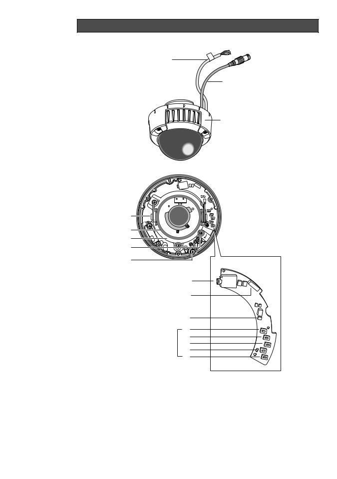
Major Operating Controls and Their Functions
q
w
e
y |
r |
|
t |
||
|
||
u |
|
|
i |
|
|
o |
|
|
!0 |
|
!1
!2
!3
!5
!6 !4 !7
!8
!9
10
qPower cable (12 V DC or 24 V AC) Cautions:
Supplies 24 V AC or 12 V DC from an external power source.
wVideo output cable with BNC connector
Connects with the video connector.
e Enclosure
rFocus lever
Fixes the focus position after adjusting.
tZoom lever
Fixes the zoom position after adjusting.
yTilting lock screw
Fixes the tilting position after adjusting.
uAzimuth (Angle adjuster)
Shoots in a straight-angle field of view when aiming at an object in a slanting direction even if the tilt angle has been set.
iPanning table
Adjusts the panning angle of the camera.
oPanning lock screw
Fixes the panning position after adjusting.
!0Camera lock screw
Fixes the camera and camera attachment.
!1Monitor output jack (3.5 diam. mini jack)
Connects the LCD monitor and such devices with 3.5 diam. 2-pole L-type plug for checking images.
!2Optional heater connector (6 pin female)
When an optional heater unit is installed in the camera, the harness exiting from the unit will be connected to this.
!3LED indicator
Shows the ABF status.
!4Operation buttons
!5SET button [(SET), ABF2/MENU]
Activates an item selected in the setup menu. Refer to p. 18 for details on the [ABF2] button.
!6DOWN button [(DOWN), ABF1]
Moves the cursor downward and selects items in the setup menu. Refer to p. 22 for details on the [ABF1] function
!7UP button (UP)
Moves the cursor upward and selects items in the setup menu.
!8LEFT button [(LEFT), NEAR]
Moves the cursor to the left, selects the mode and adjusts some levels.
!9RIGHT button [(RIGHT), FAR]
Moves the cursor to the right, selects the mode and adjusts some levels.
11

Lens Mounting (WV-CW484FK, CW484SK)
1.Before mounting the lens, remove the protection sheet from the camera.
2.Mount the optional lens to the camera by turning the lens clockwise.
3.Insert the connector of lens into the connector of camera, and bind the connectors with the fixing band.
12

Installations
•The following installation should be made by qualified service personnel or system installers.
•Mounting Bracket (WV-Q114) is optional for WV-CW484F, WV-CW484FK. Use the screws provided to the Mounting Bracket.
•Mounting Bracket is provided to WV-CW484S, WV-CW484SK. Use the screws provided to this product.
Important:
•Prepare four fixing screws to be used to mount the provided camera attachment according to the material of the area where the attachment is to be installed.
Recommended tightening torque is as follows. M4: 1.6 N·m {1.18 lbf·ft}
•Do not use wood screws to fix the camera attachment since they are not strong enough to support the weight of the camera and the bracket.
•When using the provided camera attachment, make sure that either of the arrow marks faces upward.
•When the installation area is not strong enough, reinforce and strenghten it or use Mounting Bracket or Ceiling Mount Bracket (WV-Q166).
•Required pull-out capacity of a single screw/bolt is 196 N {44.06 lbf} or more.
•When using an optional mounting bracket, refer to the operating instructions of the bracket in use.
The mounting requirements are shown as follows.
Mounting |
Model |
Recommended |
Number of |
Minimum pull-out |
place |
|
screw |
screws |
strength (per 1 pc.) |
|
|
|
|
|
Ceiling/wall |
(direct mounting) |
M4 or equivalent |
4 pcs. |
196 N {44.06 lbf} |
|
|
|
|
|
Ceiling/wall |
WV-Q114 (approx. |
– |
– |
* |
|
470 g {1.04 lbs.}) |
|
|
|
|
|
|
|
|
Ceiling |
WV-Q166 (approx. |
– |
– |
* |
|
680 g {1.5 lbs.}) |
|
|
|
|
|
|
|
|
*Make sure that the installed mount bracket can support more than 5 times of the weight of the camera.
13
■ Installations
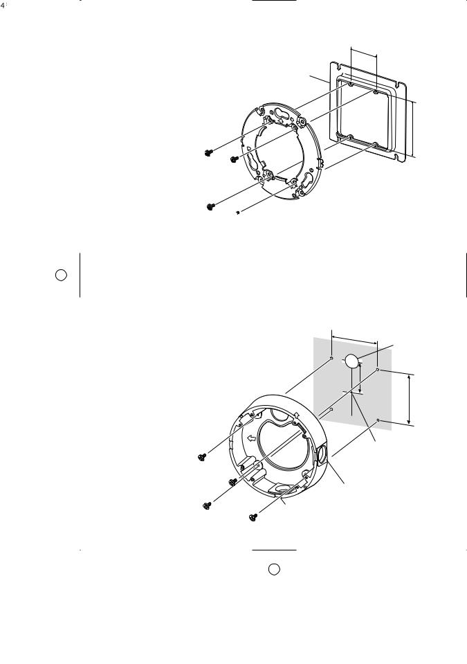
● Using a Junction Box
<Mounting hole pattern>
46 mm {1.81"}
Secure the provided camera attachment to |
|
|
the two gang junction box (4 in. x 4 in.) built |
Junction box |
|
in a wall or ceiling. |
||
|
83.5 mm {3.29"}
Camera attachment (provided)
 Screws for the camera attachment (Locally procured)
●Using Mounting Bracket
•Secure the camera mounting bracket to wall or ceiling, and fix the provided camera attachment to the mounting bracket with the screws for to the mounting bracket. (Refer to the following figures.)
Verify the camera attachment and mounting bracket are mounted firmly after screwing them.
•When routing cables sideway or through the wall/ceiling, the mounting bracket is used.
•When routing cables sideway, open the
sideway cable exit unscrewing the lid by use of a hexagon wrench. Screw the detached lid to the cable access hole on the bottom of the bracket.
•Make sure that either of the arrow marks faces upward.
TOP
Mounting
bracket |
TOP |
|
Drain slit*
<Mounting hole pattern>
85 mm {3.35"}
Cable access hole
51 mm
{2"}
85 mm {3.35"}
Bracket center
Sideway cable exit
*For wall mounting, do not face the sideway cable exits upward.
 Screws for the mounting bracket
14
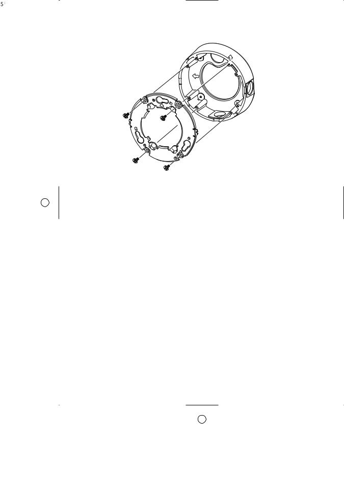
<Fixing the camera attachment to the mounting bracket>
Mounting bracket
TOP
Camera attachment (provided)
15
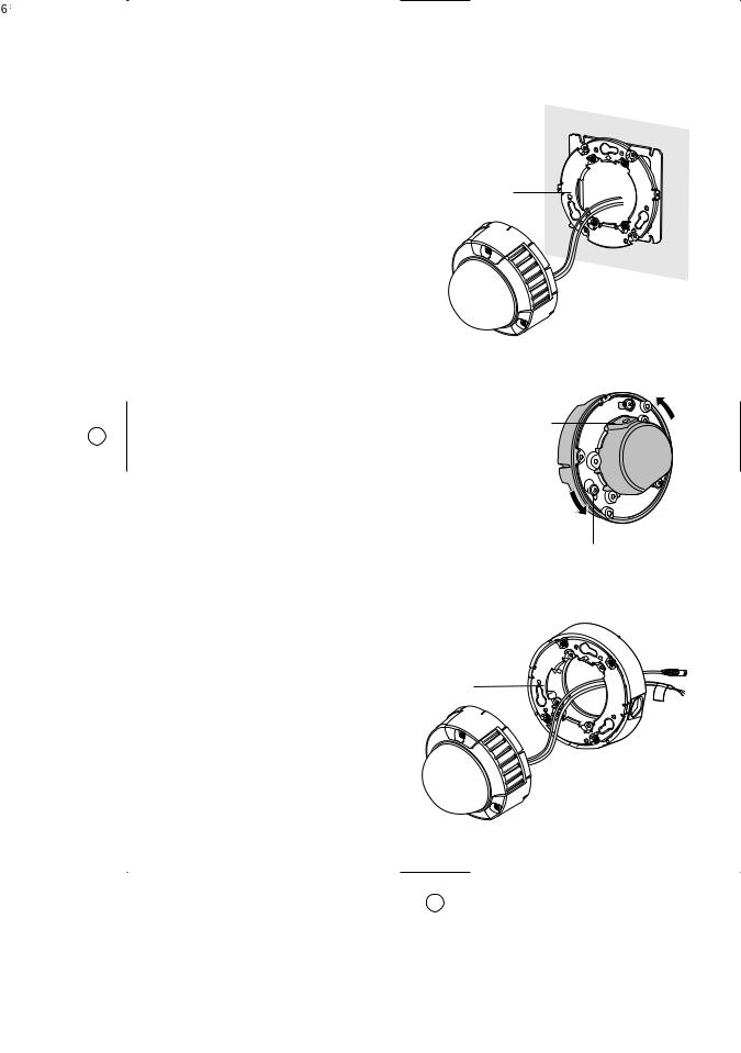
■How to mount the camera
1.Connect the power cable and the BNC plug of the video output cable. (Refer to p. 23 Connections.)
2.Secure the camera with four attachment fix-
ing screws.
<Using a Junction Box>
3. Fit the protrusion at the rear of camera unit in
Dent
the dent of camera attachment.
4.Hook the rear screws on the screw holes of camera attachment, and turn the camera unit clockwise to fix the camera unit and camera attachment.
Protrusion
Screw hole of  camera attachment
Rear screw
<Using Mounting Bracket>
3. Fit the protrusion at the rear of camera unit in the dent of camera attachment.
Dent
16
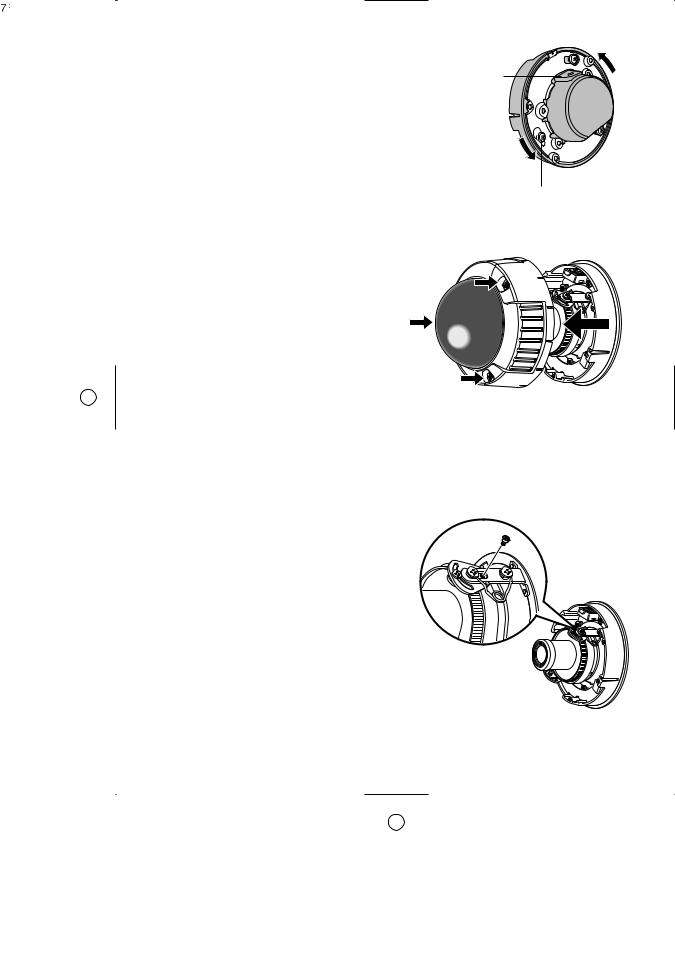
4.Hook the rear screws on the screw holes of camera attachment, and turn the camera unit clockwise to fix the camera unit and camera attachment.
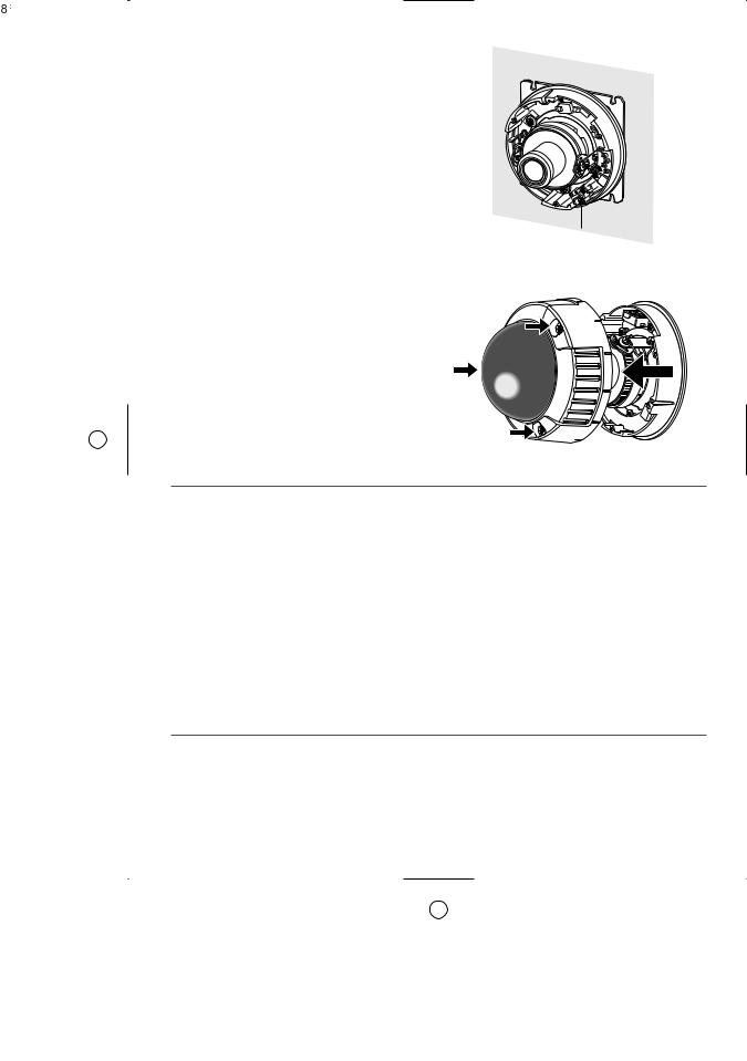
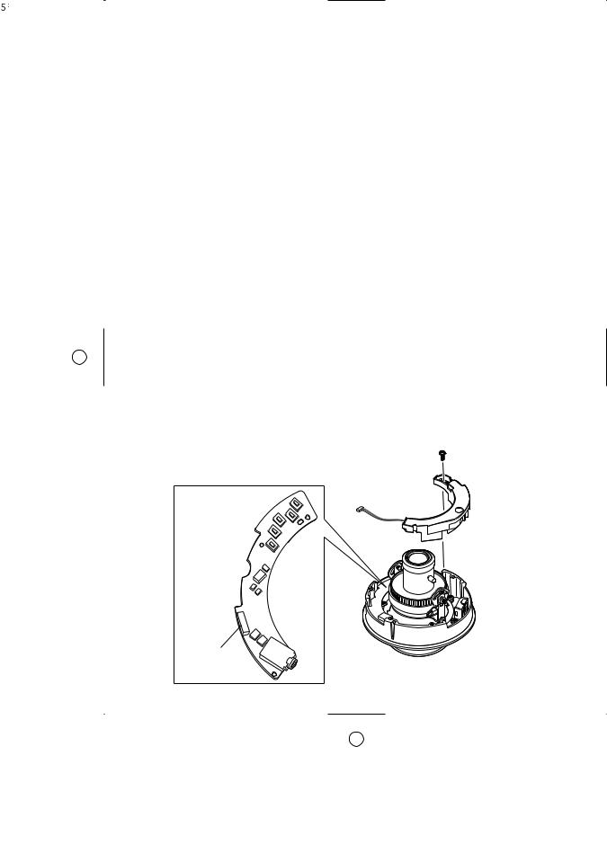
5.Remove the enclosure from the main body by loosening the three fixing screws.
The enclosure is fixed with tamperproof screws.
Loosen the three fixing screws by using the provided bit for tamperproof screw.
Note: Perform the same procedure when replacing with the optional dome cover WV-CW4C.
6.Remove the red-colored screw for transport protection with a Phillips screw driver.
Protrusion
Screw hole of  camera attachment
Rear screw
17
7. Secure the camera unit to the bracket with the camera lock screw.
(The illustration describes an example using a junction box.)
Camera fixing screw
8. Adjust the camera. (Refer to p. 21.)
9. Attach the enclosure to the camera. Firmly tighten the three tamper-proof screws.
(Recommended tightening torque 0.78 N·m {0.58 lbf·ft})
Notes:
•Defocus may be caused by the reinstalled enclosure. When using a system controller, adjust the back-focus on the setup menu after attaching the enclosure.
•When not using a system controller, back-focus adjustment is available by using the [ABF2] button after attaching the enclosure.
q Press the [ABF2] button. The LED indicator will start blinking.
w While the LED indicator is blinking (for around 3 minutes), attach the enclosure to the camera.
e When the LED indicator changes to steady light, back-focus will be adjusted automatically.
r After the back-focus is adjusted, the LED indicator will go out.
•Do not aim the camera to objects continuously moving.
•If the LED indicator blinks again after changing to steady light, back-focus adjustment may have failed. In this case, check the back-focus on the LCD monitor. To adjust the back-focus again, perform Step q to e again.
18
■Waterproof Process
•When routing cables sideway using Mounting Bracket or installing the camera under eaves, apply waterproof process to the cable and relevant portions.
•The cables are not waterproofed. Provide water sealing for the tube ends and the portions between cable cores as well as connecting portions.
•The use of vinyl tape or other tapes instead of the butyl tape may cause water absorption from a gap and finally condensation and water leakage.
● Waterproof processing of cable connection
Surely use the provided butyl tape. (Do not use a sealing material on those parts.)
1.Connect and tape the power cables.
2.Bind the power cables together with the tape.
3.Tape the BNC-BNC joint of video output cable.
Power cable 

Video output cable
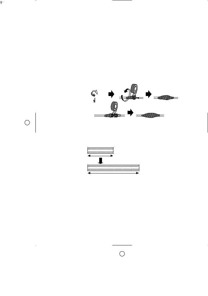
Winding the provided butyl tape
Stretch the tape to about twice its original length as shown and wind the tape around the cables. The tape will not harden if the tape is not stretched enough.
Stretch the tape to about twice.
Doubled length
19
Notes:
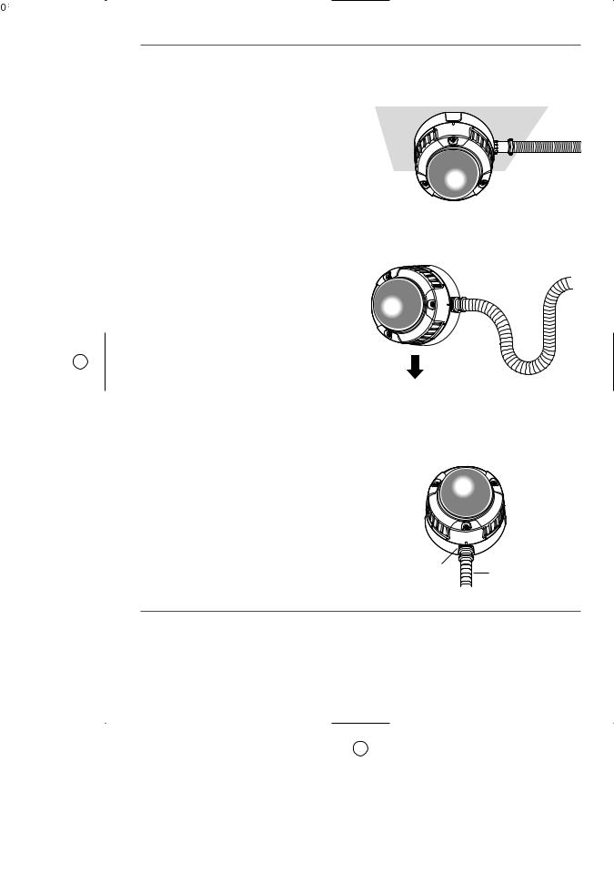
•Surely attach a pipe fitting to the bracket to avoid exposing the cables. Otherwise, cable deterioration resulting from cable exposure may cause a short circuit.
•Run the conduit downward or pull the conduit out of the side of the bracket. When pulling the conduit out of the side of the bracket, run the conduit downward once, and upward.
Downward
•For wall installation, face the drain slit downward and do not block the slit. When rain water is accumulated in the bracket, the water blocks the desiccant agent and air membrane permeation on the rear of the camera, which may cause water leakage.
Drain slit
Pipe
20
Image Adjustment
You can manually adjust the pan/tilt/azimuth angles, focus, and zoom while observing the connected monitor.
Notes:
•When connecting an LCD monitor to adjust the camera images, use an L-type mini plug. Straight type plugs are not available.
•Do not hold the camera by lens unit to adjust panning, tilting, or azimuth.
•The video output to the BNC will be interrupted while an LCD monitor is connected to the monitor output jack.
•While an LCD monitor is connected to the monitor output jack, ELC (Electric Light Control) becomes effective to obtain a proper focus. During focus adjustment, blooming or smear on highlighted objects may be caused. However, ALC (Automatic Light Control) is effective during the normal use, and blooming or smear is reduced.
•Adjust zoom and focus after adjusting panning and tilting. (Refer to Step 3 and 4.)
1.Connect an LCD monitor to the monitor output jack.
2.Pan/tilt/azimuth adjustment
•Loosen the three screws locking the pan and tilt tables.
•Pan and tilt the table to aim the camera at what you need to watch.
•Turn the azimuth adjuster to obtain a level image.
•Tighten the three screws after adjusting.
Important:
After pan/tilt/azimuth adjustment, firmly tighten the panning lock screw and tilting lock screw.
(Recommended tightening torque: 0.59 N·m {0.44 lbf·ft})
75° |
Azimuth |
|
(Angle adjuster) |
Tilting lock screw
Panning table
Monitor output Jack (3.5 diam. mini jack)
LOCK


Panning lock screw
3. Zoom
•Unlock the zoom lever.
•Move the lever to adjust the zoom.
•Lock the lever.
4. Focus
•Unlock the focus lever.
•Move the lever to adjust the focus.
•Lock the lever.
Focus lever
FAR
TELE NEAR
WIDE
Zoom lever
21

5.Aim the camera at the targeting objects and if applicable adjust the zoom angle.
6.Press the [ABF1] button.
→The LED indicator will light up, and a bar graph with "I" cursor and INDICATOR (4-digit number) will be overlaid on the camera picture.
→Back-focus will be automatically adjusted.
NEAR |
FAR |
.........|.......... |
|
INDICATOR 255 |
FOCUSING |
7.If needed, perform manual adjustment using the [LEFT] or [RIGHT] buttons to obtain the best focus on the targeted object while observing the picture. See the value of INDICATOR on the monitor. (The larger the value is, the better the picture quality becomes.)
Notes:
•The bar graph will disappear if no operation is performed for around 10 seconds.
•When changing the angular field of view, move the zoom lever and focus lever again for adjustment.
<Zoom/focus adjustment>
When shooting an object using an AF lens, the first adjusted focus may be out-of-focus depending on the focal depth of the lens in use. In this case, focus on a darker object with the aperture open to prevent out-of-focus.
When "ABF" is selected for "BACK-FOCUS" on the SETUP menu (refer to p. 41), the camera can automatically focus on a subject with the best available conditions even when the illumination changes.
•Under near-infrared light, the focus may be slightly out-of-focus than under visible light.
When the "BACK-FOCUS SETUP" page is displayed and "AUTO" or "PRESET" is selected for "C/L ↔ B/W" using the operation buttons on the camera, the camera can focus on sub-
jects both under near-infrared light and under visible light. (However, the camera will not change the focus according to the illumination change when the focus had been adjusted once.)
<How to use a variable focal lens>
Before adjusting the variable focal lens, reset the flange-back (back focal) length position to the default position for the CS-mount (by simultaneously pressing the [LEFT] and [RIGHT] buttons for 2 seconds or more, or by simultaneously pressing the [LEFT] and [RIGHT] buttons after pressing the [SET] button when the cursor is on "MANUAL-ADJ" on the "BACK-FOCUS SETUP" page.
22
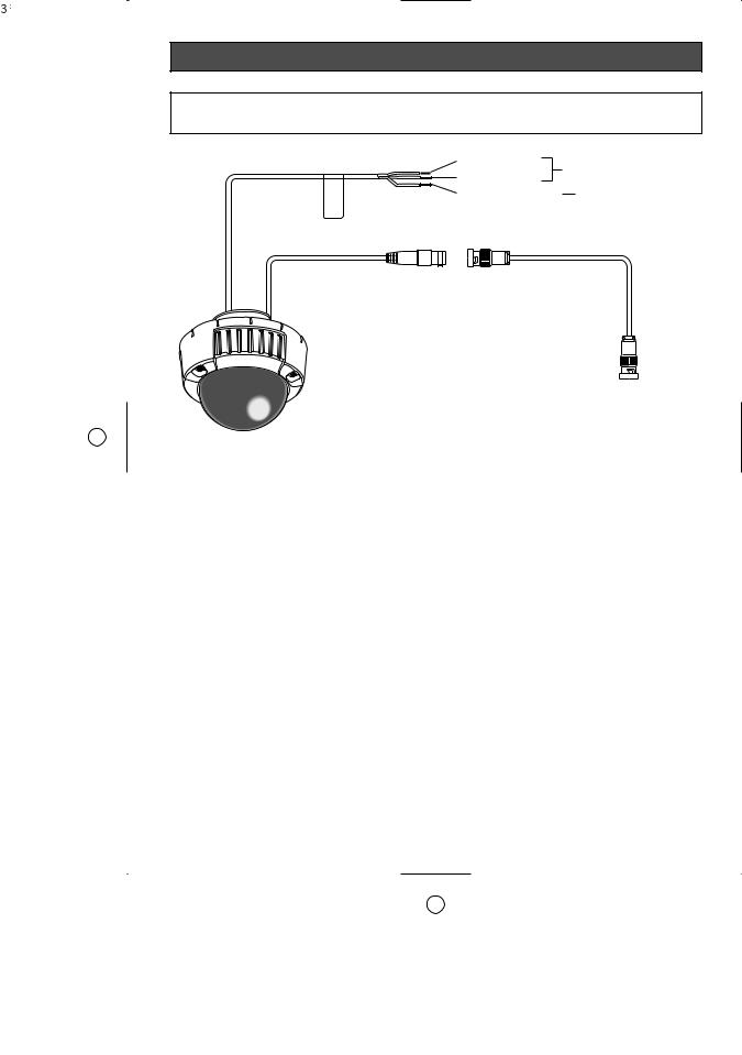
Connections
Caution:
ONLY CONNECT THIS TO 24 V AC or 12 V DC CLASS 2 POWER SUPPLY.
Power cable (Approx. 26 cm {10.24"})
Brown (Live) |
To 24 V AC or 12 V DC |
Blue (Neutral) |
power supply |
Green/Yellow (GND) |
To GND |
*When using 12 V DC power supply, the optional heater unit is unavailable.
BNC connector BNC connector
Video output cable (Approx. 22 cm {8.66"})
BNC connector
To VIDEO IN
● Video Output Connection
Connect the video output connector to the monitor or other system device with the procured coaxial cable. The maximum extensible length is shown in the table.
Type of coaxial |
|
RG-59/U |
RG-6/U |
RG-11/U |
RG-15/U |
|
cable |
|
(3C-2V) |
(5C-2V) |
(7C-2V) |
(10C-2V) |
|
|
|
|
|
|
|
|
Recommended |
|
m |
250 |
500 |
600 |
800 |
maximum |
|
|
|
|
|
|
|
|
825 |
1 650 |
1 980 |
2 640 |
|
cable length |
|
ft |
||||
|
|
|
|
|
|
|
● Power Connection
Precaution:
The following connections should be made by qualified service personnel or system installers in accordance with NEC 725-51.
• Wire Colors & Functions
Camera power cable
Wire Color |
24 V AC |
12 V DC |
|
|
|
|
|
Brown |
24 |
V AC (L) |
Positive |
|
|
|
|
Blue |
24 |
V AC (N) |
Negative |
|
|
|
|
Green/Yellow |
To GND |
|
|
|
|
|
|
Cautions:
•Be sure to connect the GND (grounding) lead of the camera and grounding terminal of the power supply when using a 24 V AC power source.
•Shrinking the cable-entry seal is a onetime procedure. Do not shrink the cableentry seal until it has been ascertained that unit is functioning.
ONLY CONNECT THIS TO 24 V AC or 12 V DC CLASS 2 POWER SUPPLY.
•To prevent fire or electric shock hazard, the UL listed wire VW-1 style 1007 should be used for the cable for Input Terminals.
•Do not use a transformer larger than 10 VA.
23

• Cable Length and Wire Gauge
24 V AC
The recommended cable length and thickness are shown in the table for reference. The voltage supplied to the power terminals of the camera should be within 19.5 V AC and 28 V AC.
Recommended wire gauge for 24 V AC line.
Copper wire |
#24 |
#22 |
#20 |
#18 |
|
size (AWG) |
|
(0.22 mm2) |
(0.33 mm2) |
(0.52 mm2) |
(0.83 mm2) |
Length of |
(m) |
20 |
30 |
45 |
75 |
Cable |
|
|
|
|
|
|
|
|
|
|
|
(Approx.) |
(ft) |
66 |
100 |
150 |
250 |
|
|
|
|
|
|
12 V DC
Use the formula below to calculate the power cable and power supply. The voltage supplied to the power terminals of the camera should be within 10.5 V DC and 16 V DC.
Resistance of copper wire [at 20 °C {68 °F}]
Copper wire |
#24 |
#22 |
#20 |
#18 |
|
size (AWG) |
(0.22 mm2) |
(0.33 mm2) |
(0.52 mm2) |
(0.83 mm2) |
|
Resistance |
0.078 |
0.050 |
0.03 |
0.018 |
|
Ω/m |
|||||
|
|
|
|
||
Resistance |
0.024 |
0.015 |
0.009 |
0.005 |
|
Ω/ft |
|||||
|
|
|
|
10.5 V DC ≤ VA - 2(R x I x L) ≤ 16 V DC L : Cable length (m) {ft}
R : Resistance of copper wire (Ω/m) {Ω/ft}
VA : DC output voltage of power supply unit
I: DC current consumption (A). See specifications.
Important: When using 12 V DC power supply, the optional heater unit is unavailable.
24
■ Optional Heater Unit WV-CW4H
● Introduction
Installing this heater unit enables the camera to operate in a low-temperature environment below –30 °C {–22 °F}. The heater turns on automatically when the temperature inside the camera drops below +10 °C {50 °F} and turns off when the temperature rises.
A small fan inside the unit will minimize condensation on the surface of the enclosure caused by changes in ambient temperature unless temperatures change too rapidly. The fan will stop when there is no possibility of condensation.
Cautions:
•When using 12 V DC power supply, the optional heater unit is unavailable.
•Turning the heater on and off may disturb the camera images.
•When servicing, pay attention to high temperature on the surface of the heater unit.
Disconnect the harness and wait until the heater unit cools.
• When you install and operate the camera in a low-temperature environment below –10 °C {14 °F}, it may take time (around 30 minutes) for the inside of the camera to warm up. In such a case, wait around 30 minutes or more.
●Installation
1.Open the enclosure.
2.Place the heater unit in the camera and fix it with the supplied screw (x1).
3.Insert the harness (x1) into the heater unit connector of the camera.
Note: Attach the desiccant pack so that it does not block ventilation holes or hang over the top of the wall.
4.Attach the enclosure.
Important: After mounting the heater unit, arrange the harness cable so as not to be tangled around the enclosure and equipment inside the camera.
Heater unit screw
Optional heater connector
25

Flange-back (Back Focal) Adjustment for Optional Lenses
This adjustment can be also performed on the setup menu.
Refer to p. 41. Back-focus Setting for details.
Important: Do not use the ABF function for continuous or repetitive purposes (ex. auto-focus etc.). This function is to be used to correct defocus caused by switching between color and black - and - white when/after installing the camera.
Hints
Before Back-focus Adjustment
•Adjustment procedures vary depending on the lens. Refer to the instructions included with the lens.
•Reset the back-focus by pressing the [LEFT] and [RIGHT] buttons simultaneously on the camera, and adjust the back-focus.
•Move the lens focus to the FAR-end when using a fixed-focal lens (lens focus adjustable type), and adjust the back-focus.
For Adjusting the Focus
•It is recommended that you lower the lighting for the object to be as dim as possible when adjusting the focus with an auto iris lens. This will make the iris open and will result in an accurate focus even though the lighting conditions vary. This may be slightly different from the best focus point in a specific lighting condition.
•Compared with cases under visible lights, using near-infrared lights may somewhat deviate the focus. It is recommended that you select AUTO or PRESET for C/L ↔
B/W in the BACK-FOCUS SETUP menu to obtain a proper focus for each of visible and near-infrared lights.
For Using General Vari-focal Lenses
1.Aim at the objects 10 meters away or more to adjust the back-focus.
2.For 8x and 10x class lenses, set the zoom to the WIDE-end and the focus to the FAR-end, and then adjust the back-focus.
3.For 2x and 3x class lenses, set the zoom to the TELE-end and the focus to the FARend, and then adjust the back-focus.
4.Aim the camera at the targeted objects to place them in the center then coarsely adjust the zoom angle and the focus of the lens. Finally, perform adjustment of the back-focus in either ways of using ABF (automatically) or MANUAL-ADJ (manually).
Note: There may be lenses having an extended range in lens focus adjustment, except Panasonic lenses. When using such a lens, set the lens focus back appropriately from the applicable end position in the above step 2 and 3 depending on the lens, and then perform back-focus adjustment. The back-focus will not be properly adjusted if the lens focus is positioned into the extended range.
26

About Setup Menus
Before operation, setup of this camera is required. On the setup menu, you can check current settings and perform settings to meet requirements.
The following is an example of setup procedure when LANGUAGE is set to ENGLISH.
Settings items of the camera setup page
|
Setup item |
Description |
Reference |
|
pages |
||
|
|
|
|
|
|
|
|
CAMERA |
Configure the settings relating to camera operations |
|
|
|
|
|
|
|
CAMERA ID |
The camera title can be edited and displayed on the |
31 |
|
|
screen. |
|
|
|
|
|
|
ALC |
Configure the light control method. |
32 |
|
|
|
|
|
SHUTTER |
Select the shutter speed. |
33 |
|
|
|
|
|
AGC |
Select the method of the gain adjustment. |
34 |
|
|
|
|
|
SENS UP |
Adjust the sensitivity. |
34 |
|
|
|
|
|
SYNC |
Configure the method of the synchronization. |
35 |
|
|
|
|
|
WHITE BAL |
Select the method of the white balance adjustment. |
35 |
|
|
|
|
|
MOTION DET |
Configure the settings for the motion detection func- |
36 |
|
|
tion. |
|
|
|
|
|
|
DNR |
Configure the settings for the DNR (Digital Noise |
38 |
|
|
Reduction) function. |
|
|
|
|
|
|
RESOLUTION |
Select a horizontal resolution mode. |
38 |
|
|
|
|
|
BW MODE |
Configure the settings relating to the BW mode such |
38 |
|
|
as the settings for switching between the color mode |
|
|
|
and the BW mode. |
|
|
|
|
|
|
PRIVACY ZONE |
It is possible to mask a designated zone and as a pri- |
39 |
|
|
vacy zone. |
|
|
|
|
|
|
EL-ZOOM |
Adjust the electronic zoom. |
40 |
|
|
|
|
|
UPSIDE-DOWN |
Select the upside down positioning of camera picture. |
40 |
|
|
|
|
|
STABILIZER |
Select "ON" or "OFF" to determine whether or not to |
40 |
|
|
use the image stabilizer to prevent shaky images. |
|
|
|
|
|
|
LENS |
Adjust the focus position automatically. |
41 |
|
|
|
|
BACK-FOCUS |
Select the method of the flange-back (back focal) |
41 |
|
|
|
length adjustment and adjust the flange-back (back |
|
|
|
focal) length minutely. |
|
|
|
|
|
27

|
Setup item |
Description |
Reference |
|
pages |
||
|
|
|
|
|
|
|
|
SPECIAL |
|
|
|
|
|
|
|
|
CHROMA GAIN |
Adjust the chroma level (color density). |
42 |
|
|
|
|
|
AP GAIN |
Adjust the aperture level. |
43 |
|
|
|
|
|
PEDESTAL |
Adjust the pedestal level (brightness). |
43 |
|
|
|
|
|
HUE |
Adjust the chroma phase. |
43 |
|
|
|
|
|
PIX OFF |
Correct image defects such as scratches. |
43 |
|
|
|
|
|
CAMERA RESET |
Reset the settings of setup menu to the default set- |
44 |
|
|
tings. |
|
|
|
|
|
|
SER.NO. |
Check the serial number of this camera. |
44 |
|
|
|
|
LANGUAGE |
Select the language to display the setup menu. |
31 |
|
|
|
|
|
28
■ Basic operation
The following are descriptions of how to configure each setup item using the operation buttons (refer to p. 10) on the camera. Setup using an optional system controller is also available.
Note:
The illustrations below are the examples to be displayed on a video monitor.
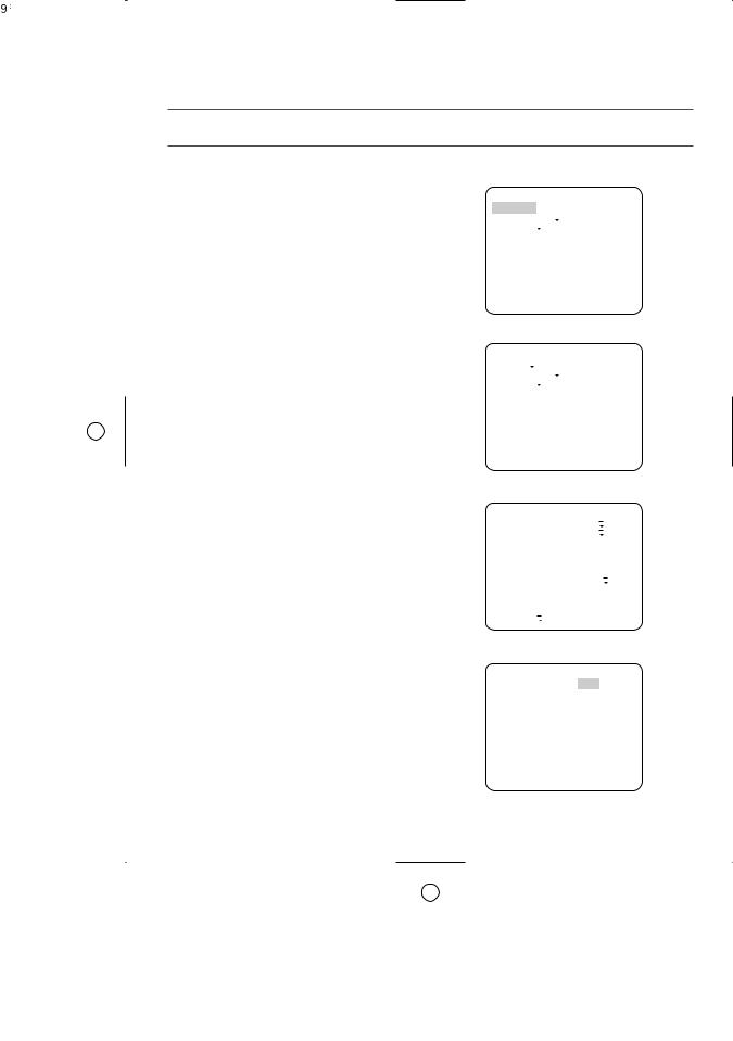
1.Hold down the [SET] button for around 2 seconds.
→The top page will be displayed.
2.Move the cursor onto "END" by press the [UP] or [DOWN] button.
3.Press the [SET] button after moving the cursor onto "SETUP" by pressing the [RIGHT] button.
→The "DISABLE" indication will change into "ENABLE" and the settings will become editable.
4.Move the cursor onto the desired setup item and press the [SET] button.
→The setup page of the selected setup item will be displayed.
5.Configure the settings for each item.
Select setup item: Move the cursor by pressing the [UP] or [DOWN] button.
Change the parameter: Press the [LEFT] or [RIGHT] button.
Display the detailed settings page of the
setup item: Press the [SET] button when the setup item with the [O] mark is
selected.
Go back to the previous page: Move the cursor onto "RET" and press the [SET] button.
Go back to the top page: Move the cursor onto "TOP" and press the [SET] button.
MODEL WV-CW484 SERIES CAMERA
BACK-FOCUS SPECIAL
 LANGUAGE
END |
SETUP DISABLE |
MODEL WV-CW484 SERIES CAMERA
BACK-FOCUS SPECIAL
 LANGUAGE
END |
SETUP ENABLE |
|
|||||||
**CAMERA SETUP** 1/2 |
|||||||||
CAMERA ID |
OFF |
|
|
|
|
|
|||
ALC |
|
ALC |
|
|
|
|
|||
|
|
|
|
|
|||||
|
|
|
|
|
|||||
SHUTTER |
|
OFF |
|||||||
AGC |
|
ON(HIGH) |
|||||||
SENS UP |
|
OFF |
|||||||
SYNC |
|
INT |
|||||||
WHITE BAL |
ATW1 |
|
|
||||||
|
|||||||||
|
|||||||||
MOTION DET |
OFF |
||||||||
DNR |
|
HIGH |
|||||||
RESOLUTION |
HIGH |
||||||||
BW MODE |
|
|
|
|
|
|
|
|
|
|
|
|
|
|
|
|
|
||
|
|
|
|
|
|
|
|
||
**CAMERA SETUP** 2/2 PRIVACY ZONE OFF EL-ZOOM OFF UPSIDE-DOWN OFF STABILIZER OFF
LENS PANASONIC
RET TOP END
29
Loading...