


Video Multiplexer
Operating Instructions
Model No. WJ-FS309
WJ-FS316
WJ-FS409
WJ-FS416
ENGLISH
POWER
ON 
OFF
POWER
ON 
OFF
|
FS |
Video Multiplexer |
WJ-FS 309 |
|
FS |
Video Multiplexer |
WJ-FS 409 |
Before attempting to connect or operate this product,
please read these instructions carefully and save this manual for future use.
FRANÇAIS
Caution:
Before attempting to connect or operate this product, please read the label on the bottom.
CAUTION
RISK OF ELECTRIC SHOCK
DO NOT OPEN
CAUTION: TO REDUCE THE RISK OF ELECTRIC SHOCK,
DO NOT REMOVE COVER (OR BACK).
NO USER-SERVICEABLE PARTS INSIDE.
REFER SERVICING TO QUALIFIED SERVICE PERSONNEL.
|
The lightning flash with arrowhead sym- |
|
|
bol, within an equilateral triangle, is |
|
|
intended to alert the user to the pres- |
|
|
ence of uninsulated "dangerous voltage" |
|
|
within the product's enclosure that may |
|
SA 1965 |
be of sufficient magnitude to constitute a |
|
risk of electric shock to persons. |
||
|
The exclamation point within an equilateral triangle is intended to alert the user to the presence of important operating and maintenance (servicing) instructions in the literature accompanying the appliance.
SA 1966
For U.S.A
NOTE: This equipment has been tested and found to comply with the limits for a Class A digital device, pursuant to Part 15 of the FCC Rules. These limits are designed to provide reasonable protection against harmful interference when the equipment is operated in a commercial environment. This equipment generates, uses, and can radiate radio frequency energy and, if not installed and used in accordance with the instruction manual, may cause harmful interference to radio communications.
Operation of this equipment in a residential area is likely to cause harmful interference in which case the user will be required to correct the interference at his own expense.
FCC Caution: To assure continued compliance, (example - use only shielded interface cables when connecting to computer or peripheral devices). Any changes or modifications not expressly approved by the party responsible for compliance could void the user’s authority to operate this equipment.
The serial number of this product may be found on the bottom of the unit.
You should note the serial number of this unit in the space provided and retain this book as a permanent record of your purchase to aid identification in the event of theft.
Model No.
Serial No.
WARNING:
To reduce the risk of fire or electric shock, do not expose this appliance to rain or moisture.
2

CONTENTS |
|
PREFACE .................................................................................................................................................................................... |
4 |
FEATURES .................................................................................................................................................................................. |
4 |
PRECAUTIONS ........................................................................................................................................................................... |
5 |
MAJOR OPERATING CONTROLS AND THEIR FUNCTIONS ..................................................................................................... |
6 |
■ Front View ............................................................................................................................................................................. |
6 |
■ Rear View ............................................................................................................................................................................. |
8 |
SETUP MENU .............................................................................................................................................................................. |
9 |
■ Setup Menu ........................................................................................................................................................................ |
10 |
■ Alarm Setup Menu .............................................................................................................................................................. |
11 |
■ Monitor Output Setup Menu ............................................................................................................................................... |
13 |
■ Record Output Setup Menu ............................................................................................................................................... |
14 |
■ Sequence Setup Menu ....................................................................................................................................................... |
15 |
■ System Setup Menu ........................................................................................................................................................... |
17 |
INSTALLATIONS ......................................................................................................................................................................... |
22 |
■ Mounting in the Rack .......................................................................................................................................................... |
22 |
SYSTEM CONNECTIONS ............................................................................................................................................................ |
23 |
■ Basic System Connection .................................................................................................................................................. |
23 |
■ Connection with the Time Lapse VCR ................................................................................................................................ |
24 |
■ Connection of the Digital Disk Recorder (Example: WJ-HD100) to a Video Multiplexer .................................................... |
25 |
■ Connection with the Monitors ............................................................................................................................................. |
26 |
■ Connection with the WV-CU360 System Controller ............................................................................................................ |
26 |
■ ALARM/REMOTE Connector .............................................................................................................................................. |
27 |
■ Connection with the Alarm Sensors ................................................................................................................................... |
28 |
■ Connection with the Alarm Output ..................................................................................................................................... |
28 |
■ Connection with the Remote (External) Switches ............................................................................................................... |
29 |
OPERATING PROCEDURES ....................................................................................................................................................... |
30 |
■ Monitoring the Camera Picture ........................................................................................................................................... |
30 |
■ Recording on the Time Lapse VCR .................................................................................................................................... |
34 |
■ Monitoring the Playback Picture ......................................................................................................................................... |
34 |
ALARM CONTROL FUNCTION ................................................................................................................................................... |
37 |
■ Alarm Input ......................................................................................................................................................................... |
37 |
■ Alarm Operation ................................................................................................................................................................. |
37 |
■ Alarm Reset ........................................................................................................................................................................ |
38 |
OTHER FUNCTIONS ................................................................................................................................................................... |
39 |
■ Camera Switching Pulse Loss Display ............................................................................................................................... |
39 |
ALL RESET .................................................................................................................................................................................. |
39 |
OPERATING CONTROL OF SYSTEM UNITS (Supplementary) .................................................................................................. |
39 |
■ Channel Loss Alarm ........................................................................................................................................................... |
39 |
APPENDIX ................................................................................................................................................................................... |
40 |
SPECIFICATIONS ........................................................................................................................................................................ |
42 |
STANDARD ACCESSORIES ....................................................................................................................................................... |
42 |
ENGLISH
3
PREFACE
The WJ-FS309 and WJ-FS316 are Black and White Video Multiplexers, and the WJ-FS409 and WJ-FS416 are Color Video Multiplexers designed for use in surveillance security systems combined with cameras, alarm sensors, a Time Lapse VCR, two video monitors and a PC. Spot pictures and image sequences of multiple cameras can be monitored simultaneously on two video monitors. Multiscreen pictures and the Multiscreen sequence pictures can be displayed on Multiscreen monitors.
Camera and playback pictures can be displayed as zoomed and stilled Spot pictures and Still Multiscreen pictures.
Setup menus for Alarm, Monitoring, Recording and Playback are available to match system preferences to your requirements.
The WJ-FS309/FS316/FS406/FS416 and other devices compatible with Panasonic Security Data mode the bear logo
 .
.
FEATURES
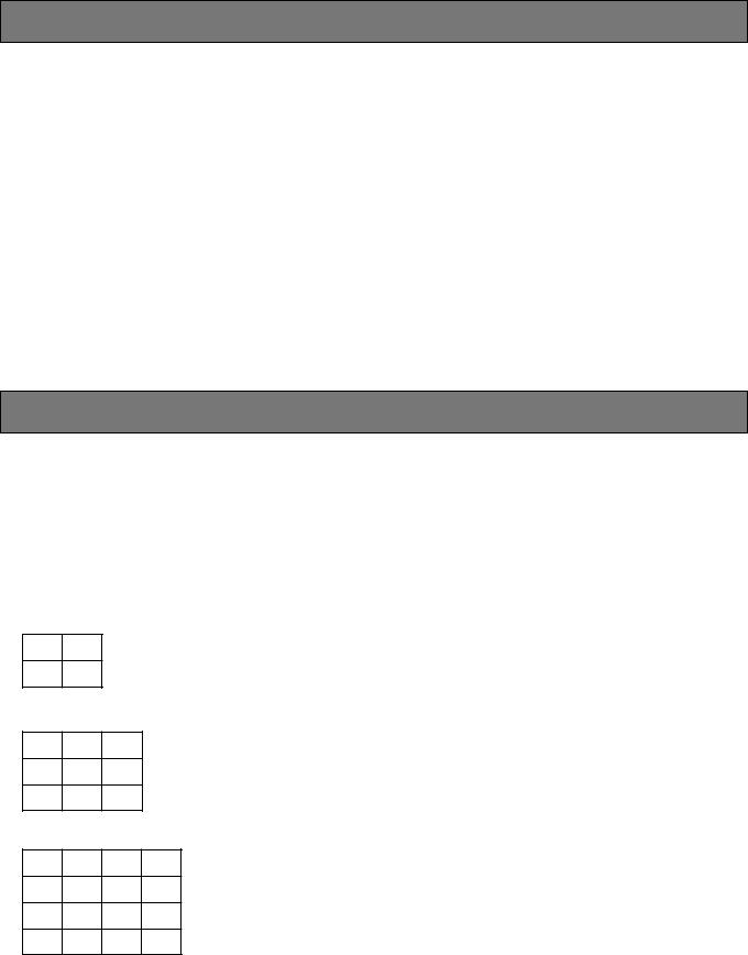
•The pictures of any connected camera can be displayed as a Spot picture on a full screen or Sequential screen, or as shown below on a 4-, 9- or 16-segment Multiscreen. Still and zoom modes (full screen only) are available both for live pictures and for video playback.
(The 16-segment multiscreen is available with WJFS316 or FS416.)
4-SEGMENT SCREEN
9-SEGMENT SCREEN
16-SEGMENT SCREEN
•High picture quality of 720 x 480 pixels
•Multiplexed video signals with camera IDs are supplied to the Recording Output
•Versatile recording mode initiated by alarm trigger
•Playback image is displayed automatically without need to operate VCR/CAM button
•The full screen image can be zoomed in 2 times.
•Preset sequence of up to 16 (9) steps with dwell times
•Video loss detector
•On screen setup menu
•Secret view
•Versatile alarm capability
•The WJ-FS309 (/FS316/FS409/FS416) can be controlled from a PC or the System Control Unit (example: WVCU360) via an RS-485 interface.
4

PRECAUTIONS
•Refer all work related to the installation of this product to qualified service personnel or system installers.
•Do not block the ventilation opening or slots on the cover.
To prevent the appliance temperature from rising, place the appliance at least 5 cm (2 inches) away from the wall.
•Do not drop metallic parts through slots.
This could permanently damage the appliance. Turn the power off immediately and refer servicing to qualified service personnel.
•Do not attempt to disassemble the appliance.
To prevent electric shock, do not remove screws or covers.
There are no user-serviceable parts inside. Refer maintenance to qualified service personnel.
•Handle the appliance with care.
Do not strike or shake, as this may damage the appliance.
•Do not expose the appliance to water or moisture, nor try to operate it in wet areas.
Do take immediate action if the appliance becomes wet. Turn the power off and refer servicing to qualified service personnel. Moisture can damage the appliance and also cause electric shock.
•Do not use strong or abrasive detergents when cleaning the appliance body.
Use a dry cloth to clean the appliance when it is dirty. When the dirt is hard to remove, use a mild detergent and wipe gently. Afterwards, wipe off the remained part of the detergent in it with a dry cloth.
•Do not operate the appliance beyond its specified temperature, humidity or power source ratings.
Do not use the appliance in an extreme environment where high temperature or high humidity exists.
Use the appliance at temperatures within –10°C - +50°C (14°F - 122°F) and a humidity below 90 %.
The input power source for this appliance is 120 V AC 60 Hz.
5

MAJOR OPERATING CONTROLS AND THEIR FUNCTIONS
■ Front View
<WJ-FS309/FS409>
|
|
|
|
t |
|
|
|
|
|
|
|
|
|
|
|
|
|
ALARM |
|
SPOT |
|
|
|
|
|
|
|
|
|
FS |
9 |
POWER |
|
|
MULTISCREEN |
|
|
|
|
|
|
|
STILL |
EL-ZOOM |
|||
|
|
ALARM |
MULTI SCREEN |
|
|
|
CAMERA SELECT |
|
|
|
VCR |
|
|
||
|
|
|
|
|
|
|
|
|
|
|
|
||||
ON |
SWITCH |
RESET |
SELECT |
SEQ |
2 |
3 |
4 |
5 |
6 |
7 |
8 |
MENU |
CAM |
Multiplexer WJ-FS 309 |
|
|
PROTECTER |
|
|
1 |
9 |
|
|||||||||
OFF |
|
|
|
|
|
|
|
|
|
|
|
ESC |
|
||
|
|
|
|
|
|
|
|
|
|
|
|
Video |
|||
|
|
|
|
|
|
|
|
|
|
|
SET |
|
|||
<WJ-FS316/FS416>


 t
t 
|
|
SPOT |
|
|
|
CAMERA SELECT |
|
|
|
FS |
|
POWER |
ALARM |
MULTISCREEN |
2 |
3 |
4 |
5 |
6 |
7 |
STILL |
EL-ZOOM |
|
|
|
1 |
8 |
|
|
||||||
|
|
ALARM |
MULTI SCREEN |
|
|
|
|
|
|
|
|
VCR |
ON |
SWITCH |
RESET |
SELECT |
SEQ |
|
|
|
|
|
|
MENU |
CAM |
|
PROTECTER |
|
|
9 |
10 |
11 |
12 |
13 |
14 |
15 |
16 |
Video Multiplexer WJ-FS 316 |
OFF |
|
|
|
|||||||||
|
|
|
|
|
|
|
|
|
|
ESC |
||
|
|
|
|
|
|
|
|
|
|
|
||
|
|
|
|
|
|
|
|
|
|
SET |
|
qPower Switch (POWER ON/OFF)
This switch turns the power of the video multiplexer on or off. The LED lights up when the power is turned on.
Note: To prevent that the power of the video multiplexer is turned off accidentally, install the supplied switch protector as shown below.
SWITCH
PROTECTOR
wAlarm Reset Button (ALARM RESET)
This button resets the active Alarm mode. Pressing this button turns off the Alarm indicator and replaces the “Alarm” indication on the monitor screen with the cam-
era title.
eAlarm Indicator (ALARM)
This indicator blinks when an alarm is activated. It changes to steady light when the auto-reset time has elapsed or the alarm recovery signal is received from the VCR. To turn the indicator off, press the ALARM RESET button.
rMultiscreen Selection Button (MULTISCREEN SELECT)
This button selects the multiscreen pattern for the monitor. Multiscreen is available only MULTI OUTPUT mode. Pressing this button repeatedly switches patterns as follows:
Multiscreen Picture:
4→ 9→ 4 screen segments (WJ-FS309/FS409)
4→ 9→ 16→ 4 screen segments (WJ-FS316/FS416) Note: When ON is selected for QUAD SHIFT on the
MONITOR OUTPUT SETUP menu, the screen
changes by pressing this button as follows:
4A→ 4B→ 9 screen segments (WJ-FS309/FS409) 4A→ 4B→ 4C→ 4D→ 9→ 16 screen segments
(WJ-FS316/FS416)
6

The 4A screen is a compressed picture of channels 1 through 4, the 4B of channels 5 through 8, the 4C of channels 9 through 12, and the 4D of channels 13 through 16. The 9-segment screen shows the pictures of channels 1 through 9 in a 3x3 pattern.
tSpot/Multiscreen Selection Button (SPOT/MULTISCREEN)
This button is used to select either the Spot output or Multiscreen output.
ySequence Button (SEQ)
This button activates the sequence mode. In this mode, a series of camera pictures is displayed in succession on the monitor screen for the specified duration.
uCamera Selection Buttons (CAMERA SELECT)
These buttons select the camera for live picture or picture recorded on the tape. When the VCR is in playback mode and the LED on the VCR/CAM button is on, these buttons select the specified camera picture from the tape for display on the monitor. When the LED is off, the buttons select the live picture of the specified camera.
iCursor Buttons (C, D, A, B)
These buttons move the cursor in the SETUP MENU of the Video Multiplexer, or select an area for Electronic Zooming.
C: Downward D: Upward A: Left
B: Right
oIncrement/Decrement Buttons (–, +)
Electronic Zooming is operated with these buttons, Zoom In with the + button and Zoom Out with the – button. During the setup, these buttons are used to select parameters.
!0Set Button (SET)
This button executes the selected parameter in the setup menu, and opens a submenu for more detailed settings. Menu items having a submenu are identified by a return symbol at the end of the line.
!1Still Button (STILL)
This button selects either still or moving mode for display on the multiscreen output monitor. Pressing a CAMERA SELECT button will display the corresponding picture either in still or moving mode. When a still picture is displayed, the LED lights. Pressing the button again restores the moving picture and turns off the LED. Note: Please note that the tape continues running while
the picture is stilled. You may sometimes have to rewind the tape to the desired position.
!2Electric Zoom Button (EL-ZOOM)
This button specifies the zooming area in the multiscreen output picture. Pressing this button displays the “+” sign representing the center of the area to be enlarged. While the “+” sign is displayed for 5 seconds, move the “+” sign with the cursor buttons to the desired position and press the Increment (+) button. The designated area is enlarged.
To return to the normal picture press the Decrement (–) or the EL-ZOOM button.
!3MENU/ESC Button (MENU/ESC)
Pressing this button for 2 seconds or more opens the Setup Menu of the Video Multiplexer. If pressed for less than 1 second, it functions as the Escape button and returns you to the previous menu.
To close the Setup menu when the setup is completed, press the button for 2 seconds.
Notes:
•Make sure to distinguish between 1-second and 2- second operation of this button.
•Opening the Setup menu does not affect the recording signal (REC OUT) output from the rear panel.
!4VCR/Camera Selection Button (VCR/CAM)
This button selects either VCR playback or the camera picture for display on the monitor. At the same time, it disables or enables recording on the VCR, since the connected VCR performs only playback or recording at a time. The playback picture is displayed on the monitor if you start playing back the VCR while the LED (Green) is on. The camera picture is displayed on the monitor while the LED is off. The camera picture is recorded on the tape if you start the VCR recording.
Notes:
•If PLAYBACK AUTO is set to ON in the setup, pressing this button is ignored, instead this button follows the VCR status automatically. VCR is selected while playing back, and CAMERA is selected during non-playback mode of the VCR.
•There may be a delay of a few seconds after
switching this button between VCR and CAMERA when PLAYBACK AUTO is ON.
*The picture may be disturbed for a moment after switch between VCR and camera.
•Blinking of the LED is a warning that the ID code is missing in the playback signal. This may happen when using certain VCR types. In this case, the playback picture goes straight to the monitor instead of through the Video Multiplexer. As a result, the playback picture will not be recognizable unless only a single channel is recorded throughout the tape.
Note: Do not press more than two buttons on the front panel simultaneously. This may cause malfunction.
7
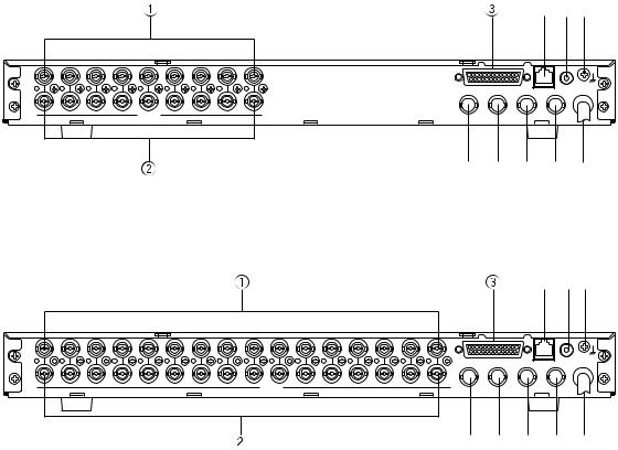
■ Rear View
<WJ-FS309/FS409>
i o!0
9 |
8 |
7 |
6 |
5 |
4 |
3 |
2 |
1 |
|
|
|
IN |
|
|
|
|
|
|
|
|
|
|
|
|
|
|
|
|
|
|
|
|
|
|
SIGNAL |
|
|
|
|
|
|
|
|
ALARM/REMOTE |
DATA |
CAMERA |
GND |
|
|
|
|
|
|
|
|
|
|
SW IN |
|
OUT |
|
|
|
|
|
|
|
|
|
|
|
9 |
8 |
7 |
6 |
5 |
4 |
3 |
2 |
1 |
|
|
|
|
|
|
|
VIDEO |
|
|
|
MULTI |
|
|
|
|
|
|
|
|
|
|
PLAY IN REC OUT SCREEN OUT |
|
SPOT OUT |
|
|
|
|
|
|
|
|
|
|
|
|


 u !1
u !1
<WJ-FS316/FS416>
i o!0
16 |
15 |
14 |
13 |
12 |
11 |
10 |
9 |
8 |
7 |
6 |
5 |
4 |
3 |
2 |
1 |
|
|
|
IN |
|
|
|
|
|
|
|
|
|
|
|
|
|
|
|
|
|
|
|
|
|
|
|
|
|
|
|
|
|
|
|
|
|
|
|
|
SIGNAL |
|
|
|
|
|
|
|
|
|
|
|
|
|
|
|
ALARM/REMOTE |
DATA |
CAMERA |
GND |
|
|
|
|
|
|
|
|
|
|
|
|
|
|
|
|
|
SW IN |
|
OUT |
|
|
|
|
|
|
|
|
|
|
|
|
|
|
|
|
|
|
16 |
15 |
14 |
13 |
12 |
11 |
10 |
9 |
8 |
7 |
6 |
5 |
4 |
3 |
2 |
1 |
|
|
|
|
|
|
|
|
|
|
|
VIDEO |
|
|
|
|
|
|
MULTI |
|
|
|
|
|
|
|
|
|
|
|
|
|
|
|
|
|
PLAY IN REC OUT SCREEN OUT |
|
SPOT OUT |
|
|
|
|
|
|
|
|
|
|
|
|
|
|
|
|
|
|
|


 u !1
u !1
q Video Input Connectors (VIDEO IN) |
y Multiscreen Output Connector (MULTISCREEN OUT) |
These connectors accept a composite video signal |
The video output signal for the multiscreen monitor is |
from a camera. |
provided via this connector. |
Note: If the input signals have a high jitter content, as in |
|
the case of a VCR playback picture, it may not be |
u Spot Output Connector (SPOT OUT) |
possible to synchronize this unit. |
Provides the video output signal for the spot monitor. |
w Video Output Connectors (VIDEO OUT) |
i Data Port (DATA) |
The video signals connected to the Video Input Connectors (VIDEO IN) are looped through to these connectors with an automatic 75 Ω termination.
eAlarm/Remote Control Connector (ALARM/ REMOTE)
This connector accepts the alarm signals from the associated alarm sensor units and the control signals from the external system.
rPlayback Input Connector (PLAY IN)
The playback signal from the time lapse VCR is supplied to this connector.
t Record Output Connector (REC OUT)
For exchange control data with the WV-CU360 System Control Unit or a PC within a system.
oCamera Switching Input Connector (CAMERA SW IN)
The camera switching pulse from the time lapse VCR is supplied to this connector.
The camera switching interval (Sequential Dwell Time) can be synchronized with the time lapse mode set in the associated time lapse VCR.
!0Signal Ground Terminal (SIGNAL GND)
!1Power Cord
The recording signal for the time lapse VCR is provided via this connector.
8
SETUP MENU
In the SETUP MENU you can set preferences for ALARM, MONITOR, REC OUT, SEQUENCE and SYSTEM to meet your requirements.
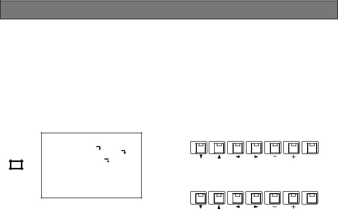
●Displaying the SETUP MENU
1.Confirm that the camera and peripherals are connected correctly and securely.
2.Turn on the power switches of all system components.
3.Press the MENU/ESC button for 2 seconds or more. The SETUP MENU appears on the monitor as shown below.
WJ-FS316 SETUP
ALARM SETUP
MONITOR OUTPUT SETUP
MENU REC OUTPUT SETUP 


SEQUENCE SETUP
SYSTEM SETUP 


ESC
The items of the WJ-FS309/FS409 SETUP MENU are the same as in the WJ-FS316/FS416 SETUP MENU.
• The following buttons are used in the SETUP MENU:
C: Moves the cursor downward. D: Moves the cursor upward. A: Moves the cursor to the left. B: Moves the cursor to the right.
– : Selects the mode or parameter. + : Selects the mode or parameter.
SET: Executes the selections and displays a submenu for an item with the ( 

 ) mark.
<WJ-FS309/FS409>
1 |
2 |
3 |
4 |
5 |
6 |
7 |
SET
<WJ-FS316/FS416>
9 |
10 |
11 |
12 |
13 |
14 |
15 |
SET
•Press the MENU/ESC button to execute the currently highlighted setting and return to the previous menu in the SETUP MENU.
•To finalize the setting and return to normal viewing, press the MENU/ESC button for 2 seconds while the SETUP MENU is displayed.
Note: If alarm is activated during the setup operation, the SETUP MENU disappears and the display returns to the normal picture. Any settings previously made take effect, even if the MENU/ESC button was not pressed yet.
9

■ Setup Menu
As shown below, the SETUP MENU has five main submenus: Alarm Setup, Monitor Output Setup, Record Output Setup, Sequence Setup and System Setup.
All of these submenus are further divided into additional submenus.
SETUP MENU
ALARM SETUP
(Alarm Setup)
MONITOR OUTPUT SETUP
(Monitor Output Setup)
REC OUTPUT SETUP
(Record Output Setup)
SEQUENCE SETUP
(Sequence Setup)
SYSTEM SETUP
(System Setup)
DYNAMIC REC |
Page 11 |
|||
(Dynamic Recording) |
|
|||
ALM REC MODE (Alarm Recording Mode) |
|
|||
AUTO RESET (Automatic Reset) |
|
|||
ALM DISPLAY (Alarm Display) |
|
|||
ALM OUTPUT (Alarm Output Duration) |
|
|||
ALM BUZZER (Alarm Buzzer Duration) |
|
|||
ALM INPUT (Alarm Input) |
|
|||
VIDEO LOSS (Video Input Signal Loss Alarm) |
|
|||
MLT OUT MODE (Alarm Channel Multiscreen Output Mode) |
|
|||
SPT OUT MODE (Alarm Channel Spot Output Mode) |
|
|||
MULTI OUTPUT |
Page 13 |
|||
|
|
|
TITLE DISP (Camera Title Display) |
|
|
|
|
||
|
|
|
STILL DISP (Still Display) |
|
|
|
|
||
|
|
|
BORDER (Border Display) |
|
|
|
|
|
|
|
|
|
QUAD SHIFT (Quad Shift) |
|
|
|
|
|
|
|
|
|
SECRET VIEW |
|
|
|
|
|
|
SPOT OUTPUT |
|
|||
|
|
|
TITLE DISP |
Page 14 |
|
|
|
||
TITLE DISPLAY (Record Title Display) |
||||
REC MODE (Recording Mode) |
|
|||
MULTI OUTPUT |
Page 15 |
|||
|
|
|
AUTO SKIP (Automatic Skip) |
|
|
|
|
|
|
|
|
|
|
|
|
|
|
SEQ MODE |
|
|
|
|
|
|
SPOT OUTPUT |
|
|||
|
|
|
AUTO SKIP (Automatic Skip) |
|
|
|
|
|
|
MLT/SPT SEQ SETUP |
|
|||
TITLE SETUP (Camera Title Setup) |
Page 17 |
|||
TITLE POSI (Camera Title Display Position) |
|
|||
CAM SW LOSS (Camera Switching Pulse Loss Alarm) |
|
|||
PLAYBACK AUTO (Automatic VCR Mode) |
|
|||
PASSWORD (Password) |
|
|||
PWR ON MULTI (Startup Multiscreen) |
|
|||
PWR ON SPOT (Startup Spot Screen) |
|
|||
COM. SETUP (Communication Setup) |
|
|||
|
|
|
UNIT ADDRESS |
|
|
|
|
|
|
|
|
|
CAM NUMBER (Camera Number) |
|
|
|
|
|
|
|
|
|
BAUD RATE |
|
|
|
|
|
|
|
|
|
DATA BIT |
|
|
|
|
|
|
|
|
|
PARITY CHECK |
|
|
|
|
|
|
|
|
|
STOP BIT |
|
|
|
|
|
|
|
|
|
WAIT TIME |
|
|
|
|
|
|
|
|
|
ALARM DATA |
|
|
|
|
|
|
ENCODE |
|
|||
|
|
|
SW INTERVAL (Field Timing) |
|
|
|
|
|
|
|
|
|
NO. OF CAMS (Camera Channel) |
|
|
|
|
|
|
10
■ Alarm Setup Menu |
<WJ-FS309/FS409> |
|
|
|
|
|
||||
|
|
|
|
|
|
|
||||
|
|
|
|
|
|
|
GROUP SETUP |
|
|
|
|
|
WJ-FS316 SETUP |
|
|
|
CH |
CH |
CH |
CH |
|
|
|
|
|
|
|
→ |
||||
|
|
ALARM SETUP |
|
|
ALM 1 |
1 |
-- |
-- |
-- |
|
|
|
MONITOR OUTPUT |
SETUP |
|
ALM 2 |
→ |
2 |
-- |
-- |
-- |
|
|
REC OUTPUT SETUP |
|
ALM 3 |
→ |
3 |
-- |
-- |
-- |
|
|
|
SEQUENCE SETUP |
|
ALM 4 |
→ |
4 |
-- |
-- |
-- |
|
|
|
SYSTEM SETUP |
|
ALM 5 |
→ |
5 |
-- |
-- |
-- |
|
|
|
|
|
|
ALM 6 |
→ |
6 |
-- |
-- |
-- |
|
|
|
|
|
ALM 7 |
→ |
7 |
-- |
-- |
-- |
|
|
|
|
|
ALM 8 |
→ |
8 |
-- |
-- |
-- |
|
|
|
|
|
ALM 9 |
→ |
9 |
-- |
-- |
-- |
|
|
|
|
|
|
|
|
|
|
|
|
|
|
|
|
|
|
|
|
|
|
Move the cursor to ALARM SETUP on the SETUP menu, then press the SET button. The ALARM SETUP menu appears on the monitor screen as shown below.
ALARM SETUP
DYNAMIC REC |
OFF |
ALM REC MODE |
004 |
AUTO RESET |
OFF |
ALM DISPLAY |
ON |
ALM OUTPUT |
2S |
ALM BUZZER |
2S |
ALM INPUT |
N.O. |
VIDEO LOSS |
ON |
MLT OUT MODE |
SPOT |
SPT OUT MODE |
SPOT |
1. DYNAMIC REC
This item lets you select the camera channel(s) whose picture is to be recorded on the VCR when an alarm signal is received. There are priority options for recording of channel(s) ranging from equal priority of all channels to exclusive recording of a specified channel.
1.Move the cursor to the DYNAMIC REC parameter.
2.Select OFF, ALM - PRI, ALM-ONLY or GROUP by pressing the + or – button.
The initial factory setting is OFF.
OFF: The video signals are recorded from channels number 1 to 9 (WJ-FS309/FS409) or 1 to 16 (WJ-FS 316/FS416) regardless of any channels receiving the alarm signal.
ALM - PRI: The video signal of the channel that received the alarm signal is recorded with more fields than normal.
ALM-ONLY: The recording output is monopolized by the picture of the channel that received the alarm, while the pictures on other channels are omitted.
Note: ALM-ONLY is not applicable, when a WJ-DR200 AV Disc Recorder is connected to the unit.
GROUP: Up to 4 channels are merged into a group. When an alarm is received, the video signals of this channel group are recorded with more fields than normal.
If the DYNAMIC REC parameter is on GROUP, proceed as follows:
<WJ-FS316/FS416>
|
|
|
|
|
|
2/2 |
|
|
|
|
GROUP SETUP |
|
1/2 |
|
|
|
|
→ |
CH |
CH |
CH |
CH |
|
|
ALM 1 |
1 |
-- |
-- |
-- |
|
|
|
ALM 2 |
→ |
2 |
-- |
-- |
-- |
|
|
ALM 3 |
→ |
3 |
-- |
-- |
-- |
|
|
ALM 4 |
→ |
4 |
-- |
-- |
-- |
|
|
ALM 5 |
→ |
5 |
-- |
-- |
-- |
|
|
ALM 6 |
→ |
6 |
-- |
-- |
-- |
|
|
ALM 7 |
→ |
7 |
-- |
-- |
-- |
|
|
ALM 8 |
→ |
8 |
-- |
-- |
-- |
|
|
|
|
|
|
|
|
|
|
|
|
|
|
|
|
|
1.Move the cursor on GROUP in the DYNAMIC REC line and press the SET button to open the GROUP SETUP menu shown above.
2.Move the cursor to the desired position by pressing the C, D, A, B buttons.
Note: To turn over the page for WJ-FS316/FS416, keep the cursor moving up or down.
3.Select the camera number by pressing the Increment (+) or Decrement (–) button.
4.Repeat steps 2 and 3 until all groupings are entered.
Note: Assigning one camera channel to plural alarm inputs is acceptable.
2.ALM REC MODE
This item lets you select the time interval (field rate) for switching the camera channel for the REC OUT signal. This setting takes effect only when an alarm is activated.
1.Move the cursor to the ALM REC MODE parameter.
2.Select a field rate or EXT by pressing the + or – button. The initial factory setting is 004.
004 - 128: REC OUT signal is switched from one camera channel to another at the field rate specified here. The appropriate field rate may vary depending on the VCR model. Consult the VCR specifications on the field rate.
EXT: Switching of the REC OUT signal is controlled by the camera switching signal supplied by the connected VCR.
11
Notes:
•If set to EXT, make sure that the CAMERA SW IN terminal on the rear panel is connected to the Time Lapse VCR.
•Depending on the mutual timing between the alarm trigger and the field rate, the initial picture recorded after an alarm is activated may not be related to the alarm.
3.AUTO RESET
This item lets you set the time the Video Multiplexer retains the alarm mode before automatic resetting to non-alarm mode. When alarm is activated the display of the camera title on the monitor alternates with “ALARM”. After the time you set, the previous, non-alarm mode is restored.
1.Move the cursor to the AUTO RESET parameter.
2.Select the desired duration by pressing the + or – button.
The initial factory setting is OFF.
OFF: Disables auto reset.
1-30S, 40S, 50S, 1-5M: Selects an alarm duration from 1-30, 40, 50 seconds or 1-5 minutes.
4.ALM DISPLAY
This item lets you enable or disable the “Alarm” display overlaid on the camera picture while the alarm is activated.
1.Move the cursor to the ALM DISPLAY parameter.
2.Select ON or OFF by pressing the + or – button. The initial factory setting is ON.
ON: Enables alarm display on the monitor. OFF: Disables alarm display on the monitor.
5.ALM OUTPUT
This item lets you select the duration of the Alarm Output signal. When the alarm signal comes in, the Alarm Output signal is supplied to the external device connected. Consult the specifications of the external device on the duration.
1.Move the cursor to the ALM OUTPUT parameter.
2.Select the parameter by pressing the + or – button. The initial factory setting is 2S.
OFF: No Alarm Output signal is supplied, regardless of an incoming alarm.
1S–30S, 40S, 50S, 1M–5M: The connected external device is driven for the duration set here. S and M stand for seconds and minutes.
EXT: The Alarm Output signal continues until the ALARM RESET button is pressed or an alarm recovery signal is supplied from the VCR.
6. ALM BUZZER
This item lets you select the ringing duration of the built-in alarm buzzer when alarm is activated.
1.Move the cursor to the ALM BUZZER parameter.
2.Select the duration by pressing the + or – button. The initial factory setting is 2S.
OFF: Disables the alarm buzzer output.
1-30S, 40S, 50S, 1-5M: Selects an alarm duration from 1-30, 40, 50 seconds or 1-5 minutes.
EXT: The alarm buzzer continues to beep until the ALARM RESET button is pressed or an external alarm recover signal is received.
7.ALM INPUT
This item lets you select the input form of the alarm signal. Consult the specifications of the sensor device.
1.Move the cursor to the ALM INPUT parameter.
2.Select the parameter by pressing the + or – button. The initial factory setting is N.O.
N.O.: Stands for Normally Open type contact. When active the contact closes.
N.C.: Stands for Normally Closed type contact. When active the contact opens.
8.VIDEO LOSS
This item lets you enable or disable the channel loss display on the monitor screen if the video signal is interrupted due to, for example, a cable disconnection.
1.Move the cursor to the VIDEO LOSS parameter.
2.Select ON or OFF by pressing the + or – button. The initial factory setting is ON.
ON: Enables the channel loss display (CHXX LOSS) on the monitor screen.
Note: XX indicates the channel number.
OFF: Disables the channel loss display on the monitor screen.
Note: If the video signal is interrupted and the message “CHXX LOSS” is displayed, check that the connections are correct and firm, then input the video signal again or press the ALARM RESET button. This resets the channel loss display.
12

9. MLT OUT MODE
This item lets you select whether to switch the multiscreen output monitor screen automatically to the camera picture of the channel whose alarm is activated.
1.Move the cursor to the MLT OUT MODE parameter.
2.Select OFF or SPOT by pressing the + or – button. The initial factory setting is SPOT.
OFF: Ignores alarm activation and continues to display the pictures in the mode selected previously. All buttons except alarm reset button do not valid on condition that alarm reset does not complete.
SPOT: The camera picture whose alarm is activated is displayed and retained until the alarm is reset.
10. SPT OUT MODE
This item lets you select whether to switch the spot output monitor screen automatically to the camera picture of the channel whose alarm is activated.
1.Move the cursor to the SPT OUT MODE parameter.
2.Select OFF or SPOT by pressing the + or – button. The initial factory setting is SPOT.
OFF: Ignores alarm activation after and continues to display the pictures in the mode selected previously. All buttons except alarm reset button do not valid on condition that alarm reset does not complete.
SPOT: The camera picture whose alarm is activated is displayed and retained until the alarm is reset.
■ Monitor Output Setup Menu
1. MULTI OUTPUT
WJ-FS316 SETUP
ALARM SETUP
MONITOR OUTPUT SETUP
REC OUTPUT SETUP
SEQUENCE SETUP
SYSTEM SETUP
Move the cursor to MONITOR OUTPUT SETUP on the SETUP menu, then press the SET button. The MONITOR OUTPUT SETUP menu appears on the monitor screen as shown below.
MONITOR OUTPUT SETUP
MULTI OUTPUT |
|
TITLE DISP |
ON |
STILL DISP |
ON |
BORDER |
WHITE |
QUAD SHIFT |
OFF |
SECRET VIEW |
OFF |
SPOT OUTPUT |
|
TITLE DISP |
ON |
1-1. TITLE DISP
This item lets you enable or disable the camera title display overlaid on the multiscreen picture.
1.Move the cursor to the TITLE DISP parameter.
2.Select ON or OFF by pressing the + or – button. The initial factory setting is ON.
ON: Enables display of the camera title. OFF: Disables display of the camera title.
1-2. STILL DISP
This item lets you enable or disable the subtitle “STILL” overlaid on the multiscreen output picture.
1.Move the cursor to the STILL DISP parameter.
2.Select ON or OFF by pressing the + or – button. The initial factory setting is ON.
ON: Enables display of the subtitle “STILL”. OFF: Disables display of the subtitle “STILL”.
13
 Loading...