


Technical Guide
2009 WiHD Plasma TV
Applies to model: GPF12ZU Chassis, 12th Generation
TC-P54Z1
Model TC-P54Z1
Panasonic Service and Technology Company
National Training
TTG090604CP/090604 |
Slide #1 |

Prepared by
Cesar Perdomo
Panasonic Service and Technology Company
National Training
"HDMI, the HDMI logo and High-Definition Multimedia Interface are trademarks or registered trademarks of HDMI Licensing LLC.“
Copyright © 2009 by Panasonic Service and Technology Company
All rights reserved. Unauthorized copying and distribution is a violation of law.
 Warning
This service information is designed for experienced repair technicians only and is not designed for use by the general public. It does not contain warnings or cautions to advise non-technical individuals of potential dangers in attempting to service a product. Products powered by electricity should be serviced or repaired only by experienced professional technicians. Any attempt to service or repair the product or products dealt with in this service information by anyone else could result in serious injury or death.
Slide #2
Table Of Contents
Subject |
Slide |
Topics |
4 |
Introduction |
5 |
Components Model Number |
6 |
Precautions |
7 |
Features |
8 |
Tuner Box |
9 |
(RF) Radio Frequency Remote Control |
10 |
Connection |
11 |
Connection |
12 |
Wired Connection |
13 |
Display Unit Only |
14 |
Wireless Setup |
15 |
Normal Wireless Connection |
16 |
Units LEDs Sequence at Power On (Wireless Connection) |
17 |
Reception Status LEDs |
18 |
Boards Layout and Description |
19 |
Display Unit Boards Layout |
20 |
Boards Layout |
21 |
Boards Name and Location (Display Unit) |
22 |
Transmitter/Receiver Boards Layout |
23 |
Signal Flow |
24 |
Wired Connection |
25 |
Digital Signal Processing (Tuner Box) |
26 |
Digital Signal Processing (Tuner Box) |
27 |
Display Unit – Digital Signal Processing (Wired) |
28 |
Display Unit – Digital Signal Processing (Wired) |
29 |
Tuner Box STB5V – STB3.3V Distribution |
30 |
Wired Connection (HDMI Only) |
31 |
Wired Connection (HDMI Only) |
32 |
Wireless Connection |
33 |
Wireless Connection |
34 |
Wireless Connection (Circuit Explanation) |
35 |
Start-up Operation |
36 |
Power Supply Voltages (Display Unit) |
37 |
Voltages Distribution |
38 |
Power Supply Voltages Distribution |
39 |
Microprocessors Commands |
40 |
Microprocessors Commands |
41 |
Standby (Display’s Main Switch Off) |
42 |
Signal Process Start-up Circuit |
43 |
Signal Process Start-up Circuit |
44 |
F+15V/SUB-Voltages Distribution |
45 |
F+15V/SUB-Voltages Distribution |
46 |
Subject |
Slide |
Sub-Voltages Applied to Signal Process Circuit |
47 |
Panel Drive Start-up Circuit |
48 |
Panel Drive Start-up Circuit |
49 |
Panel Drive Voltages Distribution |
50 |
Vsus Distribution |
51 |
Vda Distribution |
52 |
Display Unit Connectors Location |
53 |
SOS Detect (Shutdown) |
54 |
Power LED Response to Shutdown Condition |
55 |
Power LED Response to Shutdown Condition |
56 |
Display Unit SOS Detect Block Diagram |
57 |
Panel MPU SOS Detect |
58 |
Panel MPU SOS Detect (Continue) |
59 |
System MPU SOS Detect |
60 |
Tuner Box SOS Detect Block Diagram |
61 |
P15V Distribution |
62 |
Troubleshooting 2 Blinks Error Code |
63 |
P3.3V Distribution |
64 |
P3.3V Distribution (Detailed) |
65 |
Troubleshooting 3 Blinks Error Code |
66 |
Troubleshooting 4 Blinks Error Code |
67 |
P5V Distribution |
68 |
Troubleshooting 5 Blinks Error Code |
69 |
6 Blinks Error Code |
70 |
Troubleshooting 7 Blinks Error Code |
71 |
Troubleshooting 8 Blinks Error Code |
72 |
Troubleshooting 8 Blinks Error Code |
73 |
Troubleshooting 9 Blinks Error Code |
74 |
10 Blinks Error Code |
75 |
Troubleshooting 10 Blinks Error Code |
76 |
Fan Drive Circuit |
77 |
Troubleshooting 11 Blinks Error Code |
78 |
Fans Location |
79 |
12 Blinks Error Code |
80 |
Service Mode |
81 |
Service Mode (Tuner) |
82 |
Service Mode (Display Unit) (Monitor Mode) |
83 |
Display Unit Service Mode (Display Unit Unique Mode) |
84 |
Self Check/Reset (Tuner Box) |
85 |
Self Check (Display Unit) |
86 |
Wireless Unit Replacement |
87 |
RF Remote Control First Time Registration |
88 |
How to Register Additional Remote Controls |
89 |
Glossary |
90 |
Slide #3

Topics
Features
Connection
Signal Flow
Start-up Operation
Circuit Explanation
Shutdown Detect Circuit
Service Notes
Troubleshooting
Slide #4

Introduction
Z Series
A wireless Transmitter HDMI comes with the separate tuner/media unit, which sends digital wireless audio and video to the Display Unit.
The TV itself has no ports, and instead connects wirelessly to a separate box that handles all wired connections.
The flagship VIERA plasma in 2009 is the Z1 series, with a revolutionary one inch thin panel design and Wireless HD connectivity. to deliver the ultimate sleek, uncluttered HDTV viewing experience. VIERA CAST web menu with the new streaming HD movie rental capability via Amazon Video-on- Demand.
The Neo PDP design of the VIERA Z1 produces a brighter picture, deeper blacks, improved native contrast ratio (40,000:1) and Full-Time 1080 TV lines of motion resolution.
1080p resolution, a THX Certified Display; an Infinite Black panel; 600Hz Sub-field Drive; and VIERA Link, and VIERA Image Viewer for playing back digital still images and AVCHD videos recorded on SD Memory Cards.
Wireless HD technology can transmit full HD video signals, and audio and control signals wirelessly. This wireless transmission system was developed by Panasonic in collaboration with SiBEAM Inc. It can transmit uncompressed 1080p full HD content wirelessly with no deterioration in quality by using 60GHz millimeter wave radio. The picture on the screen goes undisturbed even when people interrupt the wireless communication path, and overcomes the highly directional nature of millimeter wave radio. This is achieved by incorporating beam steering technology.
Slide #5
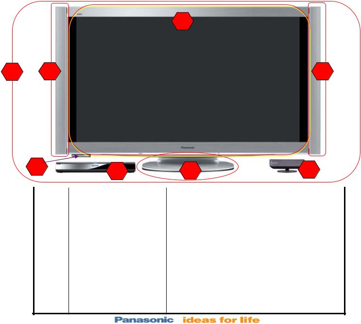
Components Model Number
2
1 |
4 |
4 |
|
8 |
3 |
5 |
7 |
|
|
|
|
|
|
|
|
Ref# |
Model Number |
|
Description |
|
|
1 |
TC-P54Z1 |
|
As System |
|
|
2 |
TC-P54Z1M |
|
Display Unit |
|
|
|
|
|
|
|
|
3 |
TU-Z100U |
|
Tuner Box |
|
|
|
|
|
|
|
|
4 |
SP-54Z1U |
|
Speaker |
|
|
5 |
ST-54CF1WS |
|
Pedestal |
|
|
|
|
|
|
|
|
6 |
TU-WH1U |
Wireless Unit (3 – 7 – 8 – Remote Control) |
|
|
|
|
|
|
|
|
|
7 |
TU-WHT1U |
|
Wireless Unit (Transmitter) |
|
|
8 |
TU-WHR1U |
|
Wireless Unit (Receiver) |
|
Slide #6

Precautions
Radio waves from this TV may interfere with medical devices and automatic control devices.
•Do not place this TV in any medical institutions or locations with medical devices.
•Do not use this TV near any automatic control devices such as automatic doors or fire alarms.
•Keep the RF remote control, Tuner Box and Wireless Unit away at least 8.7 inches (22 cm) from the location where a cardiac pacemaker is implanted.
•Keep the transmitter away from the following devices as much as possible:
Microwave oven, Wireless LAN equipment, Bluetooth-compatible equipment, and equipments which use microwave of 2.4GHz band (Digital cordless phone, Wireless audio equipment, Game machine, Personal computer peripherals)
Wireless Unit Transmission Range
Use the Wireless Unit (Transmitter) within a straight line distance of 32 ft. (approx.) from the Wireless Unit (Receiver).
RF Remote Control Transmission Range
Use the RF remote control within the range of 7 m from the TV tuner.
Slide #7

Features
High Picture Quality
•THX® Certified Display
•Moving Picture Resolution 1080 Lines **
•600Hz Subfield Drive ***
•Infinite Black with Over 2,000,000:1 Dynamic Contrast (Native 40,000:1)
•6,144 Equivalent Steps of Gradation
•24p Cinematic Playback
•Deep Color
•New Louver Filter
•Studio Reference Mode
•Pro Setting
Others
•1-inch Slim Design
•Long Panel Life, Up to 100,000 Hours
•Mercury and Lead Free Panel
•RF Remote Controller
•BBE® ViVA HD3D Sound
*THX and the THX logo are trademarks of THX Ltd. which may be registered in some jurisdictions. All rights reserved.
**Based on APDC measurement method.
***When using cinema mode.
Smart Networking
•Cable-free Design with WirelessHD™
•VIERA CAST
•VIERA Image Viewer Photo and Video (JPEG/AVCHD/MPEG2)
•VIERA Link ( Connectivity with Network Camera )
•Game Mode
•PC Input
Power Consumption
Display Unit: (Maximum) 476 W
Tuner Box: 35 W
Wireless Unit: (Receiver) 12 W
Wireless Unit: (Transmitter) 10 W)
Standby condition
Display Unit: 0.2 W
Tuner Box: 0.2 W
Weight
Display unit Including pedestal: 83.8 lb (38.0 kg) Display Unit only: 70.6 lb (32.0 kg)
Tuner box: 6.7 lb (3.0 kg)
Wireless Unit (Transmitter): 0.7 lb (280 g) Wireless Unit (Receiver): 0.9 lb (400 g)
Slide #8
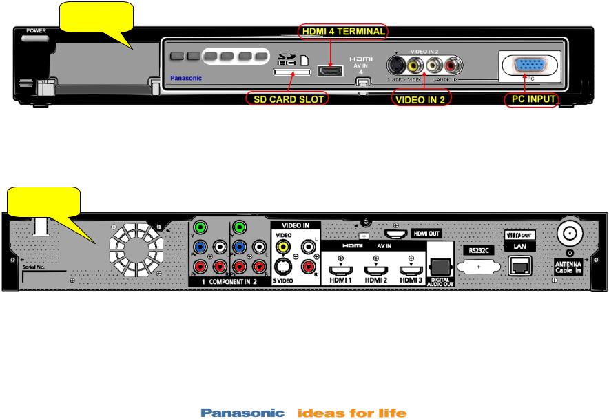
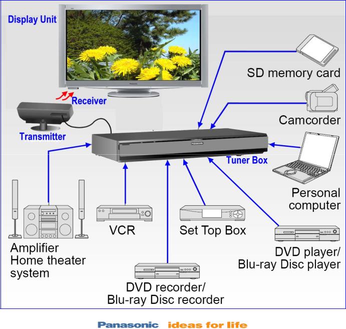
Tuner Box
The TV itself has no ports, it connects wirelessly to a separate box that handles all wired connections.
FRONT
The front side of the box has a plastic panel, under which are its ports. The front side has an SD card slot, HDMI port, S-Video port, composite cable ports, and a PC input.
REAR
The back of the box has many ports. From left to right, you'll find two component cable input ports, a composite input port, three A-V HDMI inputs, an HDMI output, a digital audio output, a RS232C port, VIERA Cast LAN input, and an antenna cable in port.
Slide #9
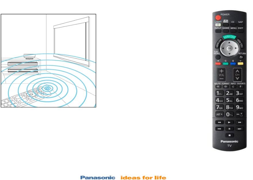
(RF) Radio Frequency Remote Control
The signals that propagate all around the room can be used to operate equipment without having to worry about the direction that the remote control is pointed. This allows easy operation of a Tuner that is placed inside an AV rack.
The TV comes with a RF Remote Control.
The Tuner Box has RF Remote Control receivers. (The Box does not have an IR Receiver).
The Display unit does not have RF receiver but it has an IR Remote Control receiver.
An IR Remote control can also be used but it has to be pointed towards the TV
This remote control uses 2.4GHz frequency. Please do not place this control near any other device which may receive interference from the frequency.
Slide #10
Connection
This Unit is designed to be connected wirelessly with the Tuner Box, but it can also be connected to the Tuner Box via the HDMI cable.
Slide #11
Connection
Slide #12
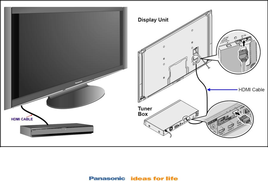
Wired Connection
The Display Unit can be connected directly to the Tuner Box using HDMI cable
If the TV is not operating because the Wireless Unit is defective, connect the Display Unit to the Tuner Box directly using the HDMI cable. The TV can be operated while the Wireless unit is been replaced.
Slide #13

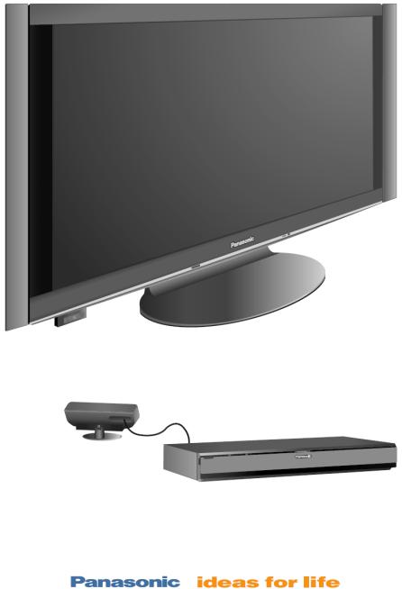
Display Unit Only (Tuner Box Disconnected)
When the Display Unit is connected only to the WiHD Receiver, the power can be turned ON and Off only with the IR remote control when it’s pointed at the Display Unit.
“No signal from tuner unit. Please check the connection between tuner unit and monitor” is displayed 20 seconds after the power button is pressed.
There’s no OSD shown when any of the R/C buttons or the VOL+, VOL-, CH+, or CHbuttons on the TV are pressed.
OSD (Service Mode Menu) can be obtained when the IR remote control, combined with the VOLbutton on the TV is used to enter the Display Unit Service Mode.
Slide #14
Wireless Setup
Slide #15
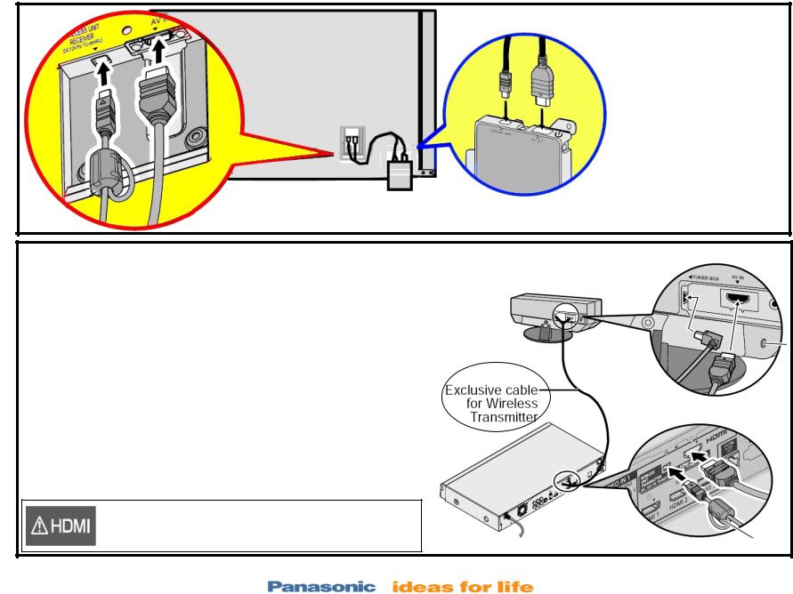
Normal Wireless Connection
The WiHD cable and the HDMI cable are used to connect the Display Unit to the wireless Receiver
The special WiHD cable and the HDMI cable are used to connect the Tuner Box to the wireless Transmitter
Note:
1.Do not connect any other device than Wireless Unit to the HDMI terminal of the Display Unit/Tuner Box.
2.Connect the Exclusive cable for Wireless Transmitter which has ferrite core to Tuner Box side.
If the connection is not correct, the following icons will be displayed when the Display unit and the Tuner box are turned on.
This Display Unit is connected to a device other than Tuner Box.
Slide #16
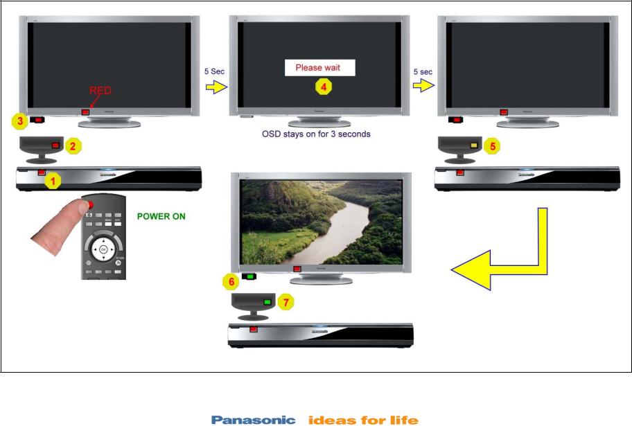
Devices LEDs Sequence at Power On (Wireless Connection)
Reception Status LEDs
Slide #17
Reception Status LEDs
Transmitter Unit and Receiver Unit.
Off: Power off |
|
|
Red: Power on and no communication |
Receiver |
|
Green: Power on and good communication |
||
LED |
Red (blinking): Indicates malfunction
Orange: Power on and communication problem (Transmitter Only)
Transmitter
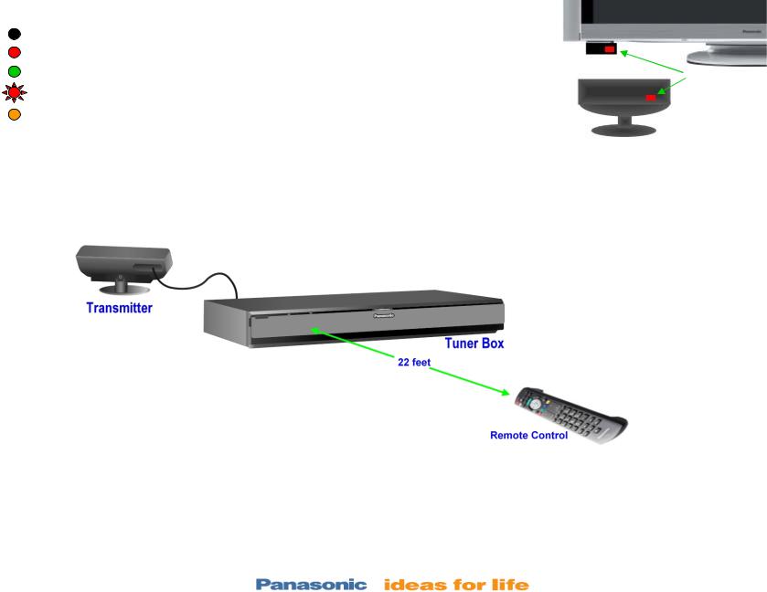
Remote Control Transmission Range
The RF remote control should be used within 22 feet from the Tuner Box.
The range may be shortened if there are any obstacles or the surrounding environment or building structure affects the transmission.
Interference from Other Devices
If the TV tuner is too close to another device, failures such as malfunction or slow remote control response may occur due to the radio wave interference.
Keep the transmitter away as much as possible from Wireless LAN, Microwaves, Telephones, Other electric devices
Slide #18

Board Layout and
Description
Slide #19

Display Unit Board Layout
Slide #20
Boards Layout
Slide #21
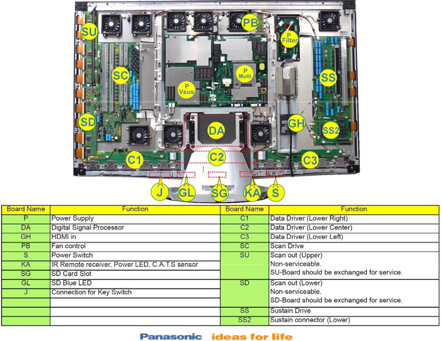
Board Name and Location (Display Unit )
Slide #22
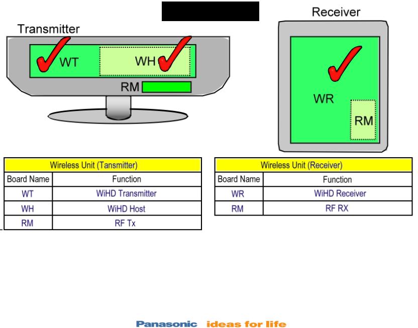
Transmitter/Receiver Board Layout
TZTWH01JSUU
The initial security settings for copyright protection are done at the factory. For this reason, The WT and WH boards in the Transmitter and the WR board in the Receiver should be replaced at the same time.
The part number for the “TRANSMISSION/RECEIVE UNIT” is TZTWH01JSUU.
Slide #23

Signal Flow
Slide #24
Wired Connection
When the Display Unit is directly connected to the Tuner Box via the HDMI cable, the IR and RF remotes can operate all the functions of the TV.
Note: The WiHD cable does not have to be connected when the Display and the Tuner are wired connected.
The Tuner Box communicates with the Display Unit via the HDMI cable making use of the DDC and CEC protocols.
The LVDS signal from the Tuner Box is output to the Display Unit through the HDMI cable.
Slide #25

Digital Signal Processing (Tuner Box)
TUNER BOX
REAR VIEW
TO DISPLAY UNIT
TUNER BOX FRONT VIEW
Slide #26

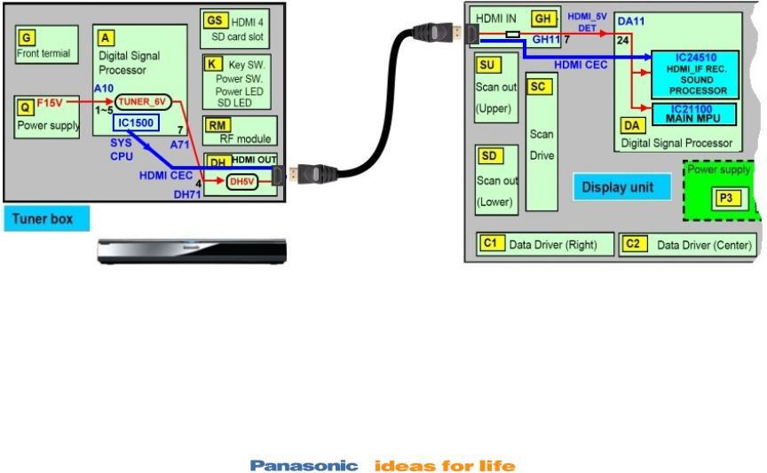
Digital Signal Processing (Tuner Box)
Circuit Explanation
The main function of the A board is to select and process one of the incoming video signals. Video inputs 1 and 2, Component Video Inputs 1 and 2, PC input, and the composite video output of the tuner are all connected to IC3001 for selection. The video output signal of the switch can be in any of the three formats: Video, Y/C, or Y, Pb, Pr. The selected output enters IC4510 (HDMI I/F Receiver/ Sound Processor).
A comb filter inside IC4510 converts the composite video signal of the main picture to Y and C (luminance and chrominance) signals. S-Video, which is already Y/C separated, simply passes through the comb filter. At the completion of this process, the format of the composite or S-Video signal is now the same as a digital 480i component signal. If the incoming video is in the 480p, 720P, or 1080i format, the Y, Pb, and Pr signals undergo A/D (analog to digital) conversion only. The 10 bit YUV data is provided to a video switch inside IC4510.
The HDMI signal from the HDMI ports is connected to IC4510 for selection.
The HDMI receiver section of IC4510 converts the incoming HDMI signals to a YUV video signal. The 36 bit RGB digital video signal is provided to the PEAKS AVC IC, IC5100.
Digital television reception of the tuner is output in the form of an IF (Intermediate Frequency) signal.
The transport stream from the tuner enters the VSB I/F (Interface) section of IC8001 where the video signal is extracted and converted to YUV data. The JPEG data of the SD card enters the JPEG I/F section of IC8001 for conversion into YUV data.
The PCI bus I/F signal is also connected to IC8001 for processing.
The selected picture data is then converted to LVDS signal and is then outputted to IC5100 (Global Core 6). OSD from IC8001 is mixed with the video signal inside IC5100.
The LVDS output from IC 5100 is provided to the DH board (HDMI Out). Here the audio signal from IC4510 is introduced to the LVDS transmitter circuit.
TMDS Data Clock, DDC IIC, and HDMI CEC from the LVDS transmitter circuit are provided to the Display unit through the HDMI cable.
Slide #27
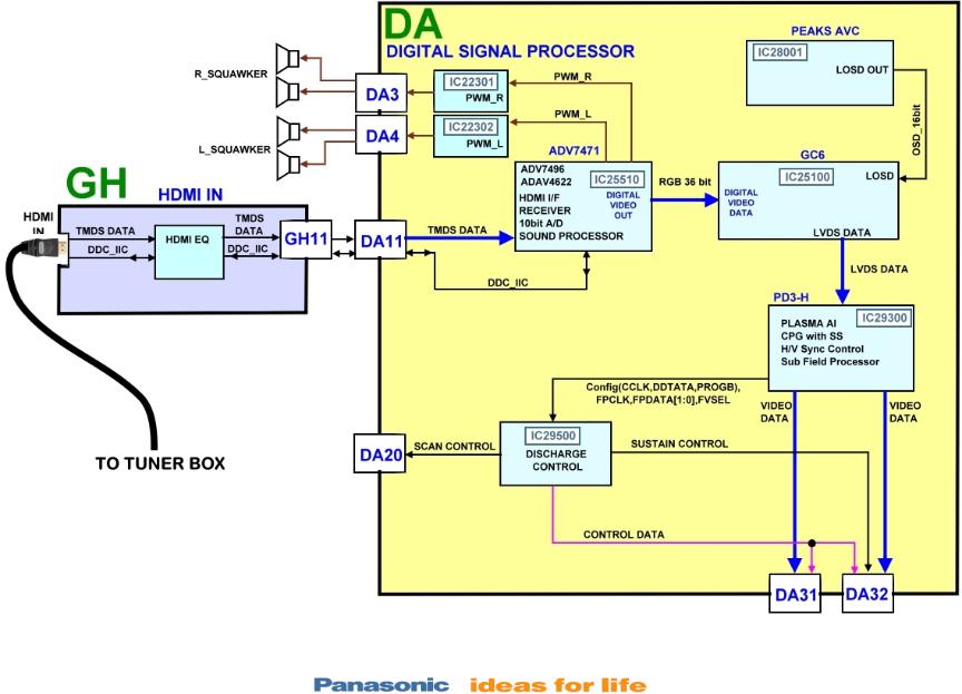
Display Unit - Digital Signal Processing (Wired)
Slide #28
 Loading...