


Safety Precautions
Observe the following notices to ensure personal safety or to prevent accidents.
To ensure that you use this product correctly, read this User’s Manual thoroughly before use. Make sure that you fully understand the product and information on safety.
This manual uses two safety flags to indicate different levels of danger.
WARNING
If critical situations that could lead to user’s death or serious injury is assumed by mishandling of the product.
-Always take precautions to ensure the overall safety of your system, so that the whole system remains safe in the event of failure of this product or other external factor.
-Do not use this product in areas with inflammable gas. It could lead to an explosion. -Exposing this product to excessive heat or open flames could cause damage to the lithium battery or other electronic parts.
CAUTION
If critical situations that could lead to user’s injury or only property damage is assumed by mishandling of the product.
-To prevent excessive exothermic heat or smoke generation, use this product at the values less than the maximum of the characteristics and performance that are assured in these specifications.
-Do not dismantle or remodel the product. It could cause excessive exothermic heat or smoke generation.
-Do not touch the terminal while turning on electricity. It could lead to an electric shock. -Use the external devices to function the emergency stop and interlock circuit. -Connect the wires or connectors securely.
The loose connection could cause excessive exothermic heat or smoke generation.
-Do not allow foreign matters such as liquid, flammable materials, metals to go into the inside of the product. It could cause excessive exothermic heat or smoke generation.
-Do not undertake construction (such as connection and disconnection) while the power supply is on. It could lead to an electric shock.
Copyright / Trademarks
-This manual and its contents are copyrighted.
-You may not copy this manual, in whole or part, without written consent of Panasonic Electric Works SUNX Co., Ltd.
-Windows is a registered trademark of Microsoft Corporation in the United States and other countries.
-All other company names and product names are trademarks or registered trademarks of their respective owners.
PLC_ORG

FP2−CCU |
Table of Contents |
|
|
Table of Contents
Interchangeability with the FP3 and Precautions . . . . . . . . . . . . . . . . . . . . . . . . . . . . . . . iii
Chapter 1 Functions of Computer Communication Unit
1.1 Functions and Features . . . . . . . . . . . . . . . . . . . . . . . . . . . . . . . . . . . . . . . . . . . . 1 − 3 1.1.1 Functions and Features . . . . . . . . . . . . . . . . . . . . . . . . . . . . . . . . . . . . 1 − 3 1.1.2 Unit Part No. . . . . . . . . . . . . . . . . . . . . . . . . . . . . . . . . . . . . . . . . . . . . . . 1 − 3
1.2 Unit Operation . . . . . . . . . . . . . . . . . . . . . . . . . . . . . . . . . . . . . . . . . . . . . . . . . . . . 1 − 4 1.2.1 Operation Overview . . . . . . . . . . . . . . . . . . . . . . . . . . . . . . . . . . . . . . . . 1 − 4
1.3 Restrictions on Units Combination . . . . . . . . . . . . . . . . . . . . . . . . . . . . . . . . . . . 1 − 6 1.3.1 Restrictions on Current Consumption . . . . . . . . . . . . . . . . . . . . . . . . 1 − 6 1.3.2 Restrictions on Installation Position . . . . . . . . . . . . . . . . . . . . . . . . . . 1 − 6 1.3.3 Restrictions on Number of Units that can be Installed . . . . . . . . . . . 1 − 7
1.4 Communication Conditions and Restrictions Relating to Functions . . . . . . . 1 − 8 1.4.1 Precautions when Using the FP2 CPU Unit−1 . . . . . . . . . . . . . . . . . 1 − 8 1.4.2 Precautions when Using the FP2 CPU Unit−2 . . . . . . . . . . . . . . . . . 1 − 9
Chapter 2 Names and Functions of Part
2.1 Names and Functions of Parts . . . . . . . . . . . . . . . . . . . . . . . . . . . . . . . . . . . . . . 2 − 3 2.1.1 Names and Functions of Parts . . . . . . . . . . . . . . . . . . . . . . . . . . . . . . 2 − 3 2.1.2 Operating Status LEDs . . . . . . . . . . . . . . . . . . . . . . . . . . . . . . . . . . . . . 2 − 4 2.1.3 COM.1 and COM.2 Ports (9 Pins) . . . . . . . . . . . . . . . . . . . . . . . . . . . . 2 − 5 2.1.4 Transmission Format Setting Switch . . . . . . . . . . . . . . . . . . . . . . . . . 2 − 6
Chapter 3 Confirming Unit Settings and Design Contents
3.1Setting the Transmission Speed (Baud Rate) and Transmission Format . . 3 − 3
3.1.1 Transmission Format Setting Using Switch . . . . . . . . . . . . . . . . . . . . 3 − 3
3.2Confirming the I/O Allocation and Root No. . . . . . . . . . . . . . . . . . . . . . . . . . . . 3 − 5
3.2.1 I/O Allocation . . . . . . . . . . . . . . . . . . . . . . . . . . . . . . . . . . . . . . . . . . . . . |
3 − 5 |
3.2.2Confirming Root No. . . . . . . . . . . . . . . . . . . . . . . . . . . . . . . . . . . . . . . . 3 − 6
i

Table of Contents |
FP2−CCU |
|
|
Chapter 4 RS232C Port Wiring
4.1 RS232C Port Signals . . . . . . . . . . . . . . . . . . . . . . . . . . . . . . . . . . . . . . . . . . . . . . 4 − 3
4.2 Wiring between RS232C Ports . . . . . . . . . . . . . . . . . . . . . . . . . . . . . . . . . . . . . . 4 − 5 4.2.1 Connecting to a Personal Computer . . . . . . . . . . . . . . . . . . . . . . . . . 4 − 5 4.2.2 Connections with Operation Display Panel . . . . . . . . . . . . . . . . . . . . 4 − 6 4.2.3 Connections with RS232C Devices . . . . . . . . . . . . . . . . . . . . . . . . . . 4 − 7 4.2.4 Modem Connections . . . . . . . . . . . . . . . . . . . . . . . . . . . . . . . . . . . . . . . 4 − 8
Chapter 5 Troubleshooting
5.1 Operation if an Error Occurs . . . . . . . . . . . . . . . . . . . . . . . . . . . . . . . . . . . . . . . . 5 − 3
5.1.1If the ALARM LED on the Computer Communication Unit
Lights . . . . . . . . . . . . . . . . . . . . . . . . . . . . . . . . . . . . . . . . . . . . . . . . . . . . 5 − 3
5.1.2If the ERROR LED on the Computer Communication Unit
Lights . . . . . . . . . . . . . . . . . . . . . . . . . . . . . . . . . . . . . . . . . . . . . . . . . . . . 5 − 4 5.2 What to Do if an Error Occurs . . . . . . . . . . . . . . . . . . . . . . . . . . . . . . . . . . . . . . . 5 − 5
5.2.1If the ALARM LED on the Computer Communication Unit
Lights . . . . . . . . . . . . . . . . . . . . . . . . . . . . . . . . . . . . . . . . . . . . . . . . . . . . 5 − 5
5.2.2If the ERROR LED on the Computer Communication Unit
Lights . . . . . . . . . . . . . . . . . . . . . . . . . . . . . . . . . . . . . . . . . . . . . . . . . . . . 5 − 5 5.2.3 Communication is Inhibited . . . . . . . . . . . . . . . . . . . . . . . . . . . . . . . . . 5 − 6 5.2.4 If an Error Response is Returned to the Host Side . . . . . . . . . . . . . 5 − 6
Chapter 6 Specifications
6.1 Specifications . . . . . . . . . . . . . . . . . . . . . . . . . . . . . . . . . . . . . . . . . . . . . . . . . . . . . 6 − 3
6.2 Table of MEWTOCOL Command . . . . . . . . . . . . . . . . . . . . . . . . . . . . . . . . . . . . 6 − 4 6.2.1 MEWTOCOL−COM Commands . . . . . . . . . . . . . . . . . . . . . . . . . . . . . 6 − 4
6.3 Table of MEWTOCOL−COM Error Code . . . . . . . . . . . . . . . . . . . . . . . . . . . . . . 6 − 5
Record of changes . . . . . . . . . . . . . . . . . . . . . . . . . . . . . . . . . . . . . . . . . . . . . . |
R − 1 |
ii

FP2−CCU |
Interchangeability with the FP3 and Precautions |
|
|
Interchangeability with the FP3 and Precautions
Hardware interchangeability
The user should be aware that there are some differences between the FP2 and FP3 Computer Communication Units.
− The DIP switch settings are different.
With the FP2 Computer Communication Unit, only the transmission speed and the character bit can be set with the DIP switches. The settings for the parity, the stop bit length, and whether or not the CS and CD control signals are effective are fixed as shown in the table below.
− There is no reset switch.
The FP2 Computer Communication Unit has no reset switch.
− Connections with serial devices are made in the same way for both units.
The specifications for the RS232C interface of the FP2 Computer Communication Unit are the same as those for the FP3.
− Two ports are provided, a “COM.1” port and a “COM.2” port.
However, the COM.1 port is restricted on the functions as below.
|
COM.1 |
COM.2 |
|
|
|
Computer link function |
Available |
Available |
|
|
|
Modem connection |
Not available |
Available |
|
|
|
Data transmission |
Not available |
Available |
|
|
|
Hierarchy command |
Not available |
Available |
|
|
|
Software interchangeability
The software is interchangeable between the FP2 and FP3 Computer Communication Units.
− Program methods on the host side are largely the same.
There are some differences in the transmission formats, as described below.
iii

Interchangeability with the FP3 and Precautions |
FP2−CCU |
|
|
Comparison of specifications between the FP2 and FP3 Computer Communication Units
Setting item |
Set value |
FP2 |
FP3 |
|
|
|
|
|
|
No. of ports |
— |
2 ports |
1 port |
|
|
|
|
|
|
Transmission speed (Baud rate) |
19,200 bits/s |
φ |
φ |
|
|
|
|
|
|
|
9,600 bits/s |
φ |
φ |
|
|
|
|
|
|
|
4,800 bits/s |
φ |
φ |
|
|
|
|
|
|
|
2,400 bits/s |
— |
φ |
|
|
|
|
|
|
|
1,200 bits/s |
— |
φ |
|
|
|
|
|
|
|
600 bits/s |
— |
φ |
|
|
|
|
|
|
|
300 bits/s |
— |
φ |
|
|
|
|
|
|
Transmission speed (Baud rate) |
9,600 bits/s |
φ |
— |
|
when modem is connected |
|
|
|
|
2,400 bits/s |
— |
φ |
||
|
||||
|
|
|
|
|
Character bit |
7−bit |
φ |
φ |
|
|
|
|
|
|
|
8−bit |
φ |
φ |
|
|
|
|
|
|
Parity |
None |
— |
φ |
|
|
|
|
|
|
|
Odd |
φ |
φ |
|
|
|
|
|
|
|
Even |
— |
φ |
|
|
|
|
|
|
Stop bit |
1−bit |
φ |
φ |
|
|
|
|
|
|
|
2−bit |
— |
φ |
|
|
|
|
|
|
Control signals CS and CD |
Invalid |
φ |
φ |
|
|
|
|
|
|
|
Valid |
— |
φ |
|
|
|
|
|
|
Reset switch |
— |
None |
Provided |
|
|
|
|
|
φ : Default setting, or can be set using DIP switches —: Cannot be set
iv

Chapter 1
Functions of Computer Communication Unit
1.1 Functions and Features . . . . . . . . . . . . . . . . . . . . . . . . . . 1 − 3 1.1.1 Functions and Features . . . . . . . . . . . . . . . . . . 1 − 3 1.1.2 Unit Part No. . . . . . . . . . . . . . . . . . . . . . . . . . . . . 1 − 3
1.2 Unit Operation . . . . . . . . . . . . . . . . . . . . . . . . . . . . . . . . . . 1 − 4
1.2.1 Operation Overview . . . . . . . . . . . . . . . . . . . . . . 1 − 4
1.3 Restrictions on Units Combination . . . . . . . . . . . . . . . . . 1 − 6 1.3.1 Restrictions on Current Consumption . . . . . . . 1 − 6 1.3.2 Restrictions on Installation Position . . . . . . . . 1 − 6
1.3.3Restrictions on Number of Units that can be
Installed . . . . . . . . . . . . . . . . . . . . . . . . . . . . . . . . 1 − 7
1.4Communication Conditions and Restrictions
Relating to Functions . . . . . . . . . . . . . . . . . . . . . . . . . . . . 1 − 8
1.4.1Precautions when Using the
FP2 CPU Unit−1 . . . . . . . . . . . . . . . . . . . . . . . . 1 − 8
1.4.2Precautions when Using the
FP2 CPU Unit−2 . . . . . . . . . . . . . . . . . . . . . . . . 1 − 9

Functions of Computer Communication Unit |
FP2−CCU |
|
|
1 − 2

FP2−CCU |
Functions of Computer Communication Unit |
1.1 Functions and Features
1.1Functions and Features
1.1.1Functions and Features
The FP2 Computer Communication Unit is designed for use with the FP2/FP2SH progra,mmable controller. It is used as a communication interface that allows data to be read and written between an RS232C device such as a personal computer or display panel, and a CPU unit.
Host computer (Personal computer)
Operation display panel
RS232C
Can be connected to a display panel and computer.
Enables a 1:1 connection to a display panel and computer. No software program is needed for communication.
Economical peer−to−peer communication with a personal computer is possible.
This unit can be directly connected with a personal computer through RS232C to collect and write data from it without building up a large−scale network.
One unit is equipped with two ports.
One unit is equipped with two RS232C interface ports.
No communication program is needed on the PLC. (Computer link function)
The PLC automatically returns responses using the FP series’ MEWTOCOL communication protocol so that there is no need to prepare a communication program at the side of the PLC.
Connection with modem (Only COM. 2)
It is possible to receive data over telephone lines from another PLC, by connecting modem with your PLC. (Receiving only)
1.1.2 |
Unit Part No. |
|
|
|
|
|
|
|
|
|
|
Name |
|
Part No. |
|
Computer Communication Unit |
FP2−CCU |
|
|
|
|
|
|
Two D−sub connectors (9−pin) are provided as accessories with the unit.
1 − 3
Functions of Computer Communication Unit |
FP2−CCU |
1.2Unit Operation
1.2Unit Operation
1.2.1Operation Overview
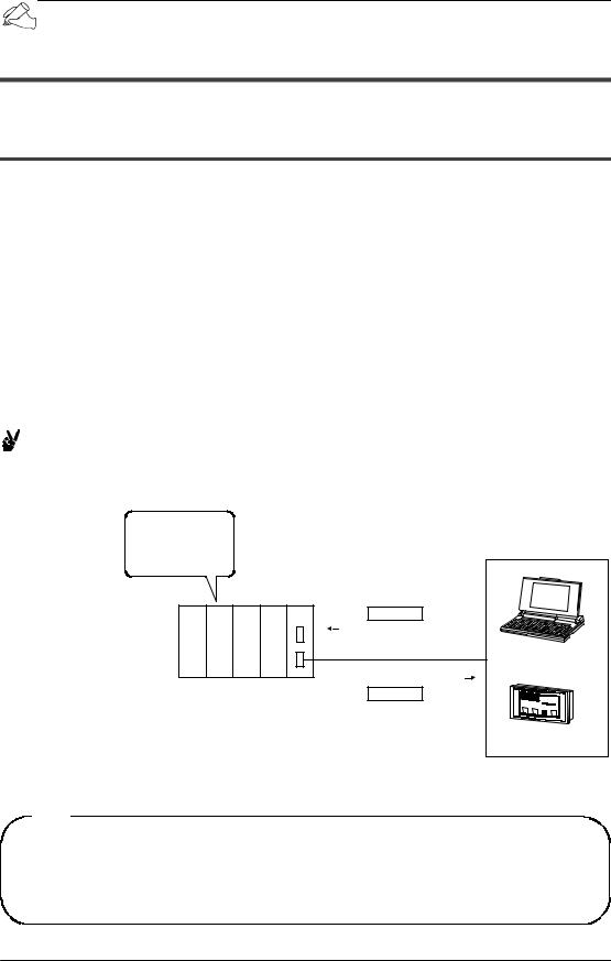
The Computer Communication Unit reads and writes data and contacts of the CPU unit by the host computer, through an RS232C interface.
When a command is sent from a host side, a response is returned from the PLC side. The formats of commands and responses are determined by the MEWTOCOL, which is the communication protocol for the FP series of PLCs.
Programs for host side devices such as computers and display panels are created in accordance with the protocol “MEWTOCOL”.
More than 20 types of commands are available, including commands for reading and writing the data area and contacts, etc.
No program is necessary on the PLC side in order to carry out communication.
Example:
When the contents of the data registers are read to a host computer:
DT0 |
5 |
DT1 |
10 |
DT2 |
3 |
Command
%01#RDD0000000001**CR |
|
|
RS232C |
Computer |
|
%01$RD05000A0062CR |
|
|
Response |
AM 5 |
|
|
3 15 |
|
|
|
|
|
|
|
|
¦ |
|
|
|
|
|
L |
|
Display panel
Tip
The display panel for the FP series was designed ahead of time in conformance with the MEWTOCOL communication protocol, so there is no need to take the contents of commands into consideration.
1 − 4
FP2−CCU |
Functions of Computer Communication Unit |
1.2 Unit Operation
Note
This unit does not support extension header (<). Use the Multi
Communication Unit.
Tip
MEWTOCOL communication protocol for FP series are generally configured as shown below.
Command format (Example showing command for reading data)
% 0 1 # R D D 0 0 0 0 0 0 0 0 0 1 * * CR
Start code
Destination 
Indicates command
Type of command
*RD stands for “Read Data”.
 End code
 BCC (Block Check Code)
 Data specification
*D 00000 00001 indicates data registers DT0 to DT1.
Response format (Example of response to data reading command)
Start code 
Source 
Indicates response Type of command
% 0 1 |
$ R D 0 5 0 0 0 A 0 0 6 2 CR |
|
(lower) (higher) (lower) (higher) |
|
End code |
|
BCC (Block Check Code) |
|
Content of data that was read 2 |
|
Content of data that was read 1 |
1 − 5

Functions of Computer Communication Unit |
FP2−CCU |
1.3Restrictions on Units Combination
1.3Restrictions on Units Combination
1.3.1Restrictions on Current Consumption
The power supply (5 V DC) used to drive the internal circuits of the Computer Communication Unit and other units is provided from the power supply unit, through the backplane.
The overall current consumption, including the current used by other units, should not exceed the rated capacity of the power supply unit.
Unit name |
Part No. |
Current consumption (at 5 V DC) |
|
|
|
FP2 Computer Communication Unit |
FP2−CCU |
60 mA or less |
|
|
|
For information on the internal current consumptions of other units, please refer to the “FP2/FP2SH Hardware Manual” and the manuals of the pertinent units.
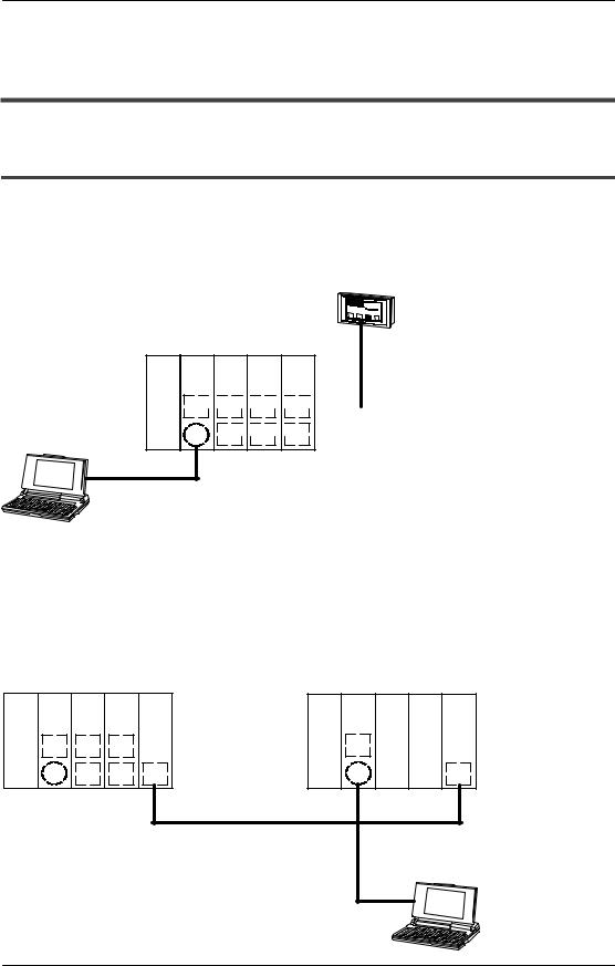
1.3.2Restrictions on Installation Position
The Computer Communication Unit can only be installed on the CPU backplane side. It should not be installed on the expansion backplane. Also, it should be installed to the right of the power supply unit and the CPU unit.
CPU backplane
Computer
Communication Unit
Can be installed only on the CPU backplane
Expansion cable
Expansion backplane
1 − 6

FP2−CCU |
Functions of Computer Communication Unit |
1.3 Restrictions on Units Combination
1.3.3Restrictions on Number of Units that can be Installed
The number of Computer Communication Units that can be installed is as shown in the table below.
Unit type |
When FP2 CPU unit is used |
When FP2SH CPU unit is used |
|
|
|
Computer Communication Unit |
Only one. |
Up to five units, using Computer Com- |
|
Up to three units can be used if they |
munication Units and Multi−wire Link |
|
are used within the range of restric- |
Unit (MEWNET−W mode) in combina- |
|
tions described under “section 1.4 |
tion. |
|
Communication Conditions and Re- |
|
|
strictions Relating to Functions”. |
|
|
|
|
Multi−wire Link Unit |
Up to three units, in combination with |
|
(MEWNET−W mode) |
Computer Communication Units. |
|
|
|
|
Tip
The above restrictions do not apply to Multi−wire Link Units set to the MEWNET−F mode and MEWNET−W2 mode.
Note
If the FP2 CPU unit is being used, make sure the restrictions relating to the following communication conditions have been carefully confirmed when deciding the number of units to be installed.
1 − 7
Functions of Computer Communication Unit |
FP2−CCU |
1.4Communication Conditions and Restrictions Relating to Functions
1.4Communication Conditions and Restrictions Relating to Functions
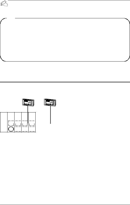
1.4.1Precautions when Using the FP2 CPU Unit −1
If the processing of commands and responses sent from a host computer or display panel extends over multiple frames, a busy error (error code 53) will be returned to other ports if communication is currently being carried out on one port, and communication will be inhibited on those other ports. Combinations to which this restriction applies are shown in the diagram below.
|
3 5 |
15 |
AM |
|
|
|
L |
|
|
||
|
¦ |
|
Powersupply CPU CCU CCU CCU
B 
 A
A 
 A
A 
 A
A 

A B 
 B
B 
 B
B
For example, during the time that a program is being read at the tool port of the CPU unit, a communication error will occur at the display panel connected to the COM.1 port of the Computer Communication Unit.
Group A . . . . .
Group B . . . . .
Group comprising the tool port of the CPU unit and the COM.1 port of the Computer Communication Unit
Group comprising the COM. port of the CPU unit and the COM.2 port of the Computer Communication Unit
A similar restriction also applies if access is being made from another station connected with the link unit.
Unit No. 1 (source station) |
Unit No. 2 (other station) |
|||||
Power |
CPU CCU CCU MW |
Power |
CPU |
MW |
||
supply |
|
|
|
supply |
|
|
|
B |
A |
A |
|
B |
|
|
A |
B |
B |
|
A |
|
When remote programming is being carried out from another station connected with a Multi−wire Link Unit (MW), a communication error will occur at the Group A ports on the source station side.
1 − 8
FP2−CCU |
Functions of Computer Communication Unit |
1.4 Communication Conditions and Restrictions Relating to Functions
Tip
−“Multiple frames” means that, if a command or response exceeds 118 bytes, the command or response is divided into multiple segments and transmitted or received.
For example, this applies in cases such as when a program is read from a tool port, when commands, which continuously read multiple data, are transmitted from a host side.
−If using the FP2SH CPU unit, the above restriction does not apply.
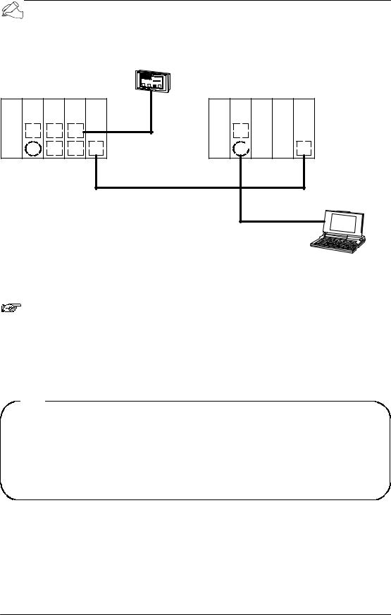
1.4.2Precautions when Using the FP2 CPU Unit−2
Of the commands sent from a host computer or display panel, if the monitor commands (the MC, MD, and MG codes) are used, they cannot be read accurately if two or more devices within the same group are connected.
|
3 15 |
|
3 15 |
||||
|
|
5 |
|
|
|
5 |
|
|
AM |
|
|
AM |
|
||
|
¦ |
|
|
¦ |
|
||
|
|
L |
|
|
L |
|
|
|
|
|
|
|
|||
|
|
|
|
|
|
|
|
Powersupply CPU CCU CCU CCU
B 
 C
C 
 C
C 
 C
C 
A  D
D 
 D
D 
 D
D 
For example, if two or more display panels in the same group are connected and the command sent from the display panel side is a monitor command, it cannot be read accurately.
Group A . . . . . CPU unit tool port Group B . . . . . CPU unit COM. port
Group C . . . . . COM.1 port group of Computer Communication Unit Group D . . . . . COM.2 port group of Computer Communication Unit
1 − 9
Functions of Computer Communication Unit |
FP2−CCU |
1.4Communication Conditions and Restrictions Relating to Functions
A similar restriction also applies if access is being made from another station connected with the link unit.
Unit No. 1 (source station)
Powersupply CPU CCU CCU MW
B C C
A D D
|
3 15 |
|
5 |
AM |
|
|
L |
|
|
|
¦ |
Unit No. 2 (other station)
Power |
CPU |
MW |
supply |
|
|
D
C
If remote programming is used to change the monitoring destination from another station connected with the Multi−wire Link Unit (MW), the monitoring destination of the Computer Communication Unit COM.1 port of the source station side will end up being changed.
Note
If a monitor command is used for a port in the same group, registered data will be rewritten in sequential order starting from the most recent data, and different data will end up being monitored.
Tip
−Monitoring commands are commands used to implement monitoring after the contact or data to be monitored has been registered on the PLC side.
−The above restriction does not apply if the FP2SH CPU unit is being used.
1 − 10

Chapter 2
Names and Functions of Parts
2.1 Names and Functions of Parts . . . . . . . . . . . . . . . . . . . . 2 − 3 2.1.1 Names and Functions of Parts . . . . . . . . . . . . 2 − 3 2.1.2 Operating Status LEDs . . . . . . . . . . . . . . . . . . . 2 − 4 2.1.3 COM.1 and COM.2 Ports (9 Pins) . . . . . . . . . . 2 − 5 2.1.4 Transmission Format Setting Switch . . . . . . . 2 − 6
 Loading...