


Operating Instructions
LCD Video Monitor
Model No.
Model No.
BT-LH80WP BT-LH80WE
Before operating this product, please read the instructions carefully and save this manual for future use.
S0507N0 -M |
ENGLISH |
Printed in Japan |
VQT1H75 |
Read this first! (For BT-LH80WP)
CAUTION
RISK OF ELECTRIC SHOCK
DO NOT OPEN
CAUTION: TO REDUCE THE RISK OF ELECTRIC SHOCK, DO NOT REMOVE COVER (OR BACK).
NO USER SERVICEABLE PARTS INSIDE. REFER TO SERVICING TO QUALIFIED SERVICE PERSONNEL.
The lightning flash with arrowhead symbol, within an equilateral triangle, is intended to alert the user to the presence of uninsulated “dangerous voltage” within the product’s enclosure that may be of sufficient magnitude to constitute a risk of electric shock to persons.
The exclamation point within an equilateral triangle is intended to alert the user to the presence of important operating and maintenance (service) instructions in the literature accompanying the appliance.
FCC Note:
This equipment has been tested and found to comply with the limits for a class A digital device, pursuant to Part 15 of the FCC Rules. These limits are designed to provide reasonable protection against harmful interference when the equipment is operated in a commercial environment. This equipment generates, uses, and can radiate radio frequency energy, and if not installed and used in accordance with the instruction manual, may cause harmful interference to radio communications. Operation of this equipment in a residential area is likely to cause harmful interference in which case the user will be required to correct the interference at his own expense.
Warning:
To assure continued FCC emission limit compliance, the user must use only shielded interface cables when connecting to external units. Also, any unauthorized changes or modifications to this equipment could void the user’s authority to operate it.
WARNING:
•TO REDUCE THE RISK OF FIRE OR SHOCK HAZARD, DO NOT EXPOSE THIS EQUIPMENT TO RAIN OR MOISTURE.
• TO REDUCE THE RISK OF FIRE OR SHOCK HAZARD, KEEP THIS EQUIPMENT AWAY FROM ALL LIQUIDS. USE AND STORE ONLY IN LOCATIONS WHICH ARE NOT EXPOSED TO THE RISK OF DRIPPING OR SPLASHING LIQUIDS, AND DO NOT PLACE ANY LIQUID CONTAINERS ON TOP OF THE EQUIPMENT.
CAUTION:
TO REDUCE THE RISK OF FIRE OR SHOCK HAZARD AND ANNOYING INTERFERENCE, USE THE RECOMMENDED ACCESSORIES ONLY.
Notice (U.S.A. only):
This product has a fluorescent lamp that contains mercury. Disposal may be regulated in your community due to environmental considerations. For disposal or recycling information, please contact your local authorities, or the Electronics Industries Alliance:
<http://www.eiae.org>
CAUTION:
In order to maintain adequate ventilation, do not install or place this unit in a bookcase, built-in cabinet or any other confined space. To prevent risk of electric shock or fire hazard due to overheating, ensure that curtains and any other materials do not obstruct the ventilation.
CAUTION:
• Keep the temperature inside the rack to between 5 °C to 40 °C (41 °F to 104 °F).
• Bolt the rack securely to the floor so that it will not topple over.
 indicates safety information.
A rechargeable battery that is recyclable powers the product you have purchased.
2
Read this first! (For BT-LH80WE)
 DO NOT REMOVE PANEL COVERS BY UNSCREWING THEM.
To reduce the risk of electric shock, do not remove the covers. No user serviceable parts inside.
Refer servicing to qualified service personnel.
WARNING:
•TO REDUCE THE RISK OF FIRE OR SHOCK HAZARD, DO NOT EXPOSE THIS EQUIPMENT TO RAIN OR MOISTURE.
• TO REDUCE THE RISK OF FIRE OR SHOCK HAZARD, KEEP THIS EQUIPMENT AWAY FROM ALL LIQUIDS. USE AND STORE ONLY IN LOCATIONS WHICH ARE NOT EXPOSED TO THE RISK OF DRIPPING OR SPLASHING LIQUIDS, AND DO NOT PLACE ANY LIQUID CONTAINERS ON TOP OF THE EQUIPMENT.
CAUTION:
In order to maintain adequate ventilation, do not install or place this unit in a bookcase, built-in cabinet or any other confined space. To prevent risk of electric shock or fire hazard due to overheating, ensure that curtains and any other materials do not obstruct the ventilation.
CAUTION:
•Keep the temperature inside the rack to between 5 °C to 40 °C.
•Bolt the rack securely to the floor so that it will not topple over.
CAUTION:
TO REDUCE THE RISK OF FIRE OR
SHOCK HAZARD AND ANNOYING
INTERFERENCE, USE THE
RECOMMENDED ACCESSORIES ONLY.
 indicates safety information.
Attention/Attentie
ENGLISH
• Battery is used for the main power source in the product.
At the end of their useful life, you should not throw them away. Instead, hand them in as small chemical waste.
NEDERLANDS
• Voor de primaire voeding van het apparaat wordt gebruikgemaakt van een batterij.
Wanneer de batterij is uitgeput, mag u deze niet gewoon weggooien, maar dient u deze als klein chemisch afval weg te doen.
TO REMOVE THE BATTERY
Main Power Battery (Ni-Cd / Ni-MH / Li-ion Battery)
•To detach the battery, please proceed in the reverse order of the installation method described in this manual.
•If a battery made by any other manufacturer is to be used, check the Operating Instructions accompanying the battery.
3

Contents
Read this first! (For BT-LH80WP). . . . . . . . . . . . . . . 2 Read this first! (For BT-LH80WE). . . . . . . . . . . . . . . 3 Standard accessory . . . . . . . . . . . . . . . . . . . . . . . . . 4 Optional unit . . . . . . . . . . . . . . . . . . . . . . . . . . . . . . . 4 Precautions for use. . . . . . . . . . . . . . . . . . . . . . . . . . 5 Outline . . . . . . . . . . . . . . . . . . . . . . . . . . . . . . . . . . . . 6 Dimensions . . . . . . . . . . . . . . . . . . . . . . . . . . . . . . . . 6 Controls and Their Functions . . . . . . . . . . . . . . . . . 7
Front panel. . . . . . . . . . . . . . . . . . . . . . . . . . . . . . . . 7 Rear panel . . . . . . . . . . . . . . . . . . . . . . . . . . . . . . . . 8
Supplying the power . . . . . . . . . . . . . . . . . . . . . . . . . 9
Using the Anton/Bauer type battery pack. . . . . . . . . 9 Using a V-mount type battery pack . . . . . . . . . . . . . 9 Using an external DC power supply. . . . . . . . . . . . 10
VF Function . . . . . . . . . . . . . . . . . . . . . . . . . . . . . . . 11 How to Use the On Screen Menu . . . . . . . . . . . . . . 12
Operating status display . . . . . . . . . . . . . . . . . . . . 12 Picture adjusting knob status. . . . . . . . . . . . . . . . . 12 Sharpness display . . . . . . . . . . . . . . . . . . . . . . . . . 13 Function display. . . . . . . . . . . . . . . . . . . . . . . . . . . 13 DC power supply voltage and battery level display 13 Menu display . . . . . . . . . . . . . . . . . . . . . . . . . . . . . 13 Menu operations . . . . . . . . . . . . . . . . . . . . . . . . . . 14
User Data . . . . . . . . . . . . . . . . . . . . . . . . . . . . . . . . . 15
Saving user data . . . . . . . . . . . . . . . . . . . . . . . . . . 15 Loading user data . . . . . . . . . . . . . . . . . . . . . . . . . 15
Main Menu . . . . . . . . . . . . . . . . . . . . . . . . . . . . . . . . 16
Menu configuration . . . . . . . . . . . . . . . . . . . . . . . . 16 MARKER . . . . . . . . . . . . . . . . . . . . . . . . . . . . . . . . 17 Types of MARKER. . . . . . . . . . . . . . . . . . . . . . . . . 18 VIDEO CONFIG. . . . . . . . . . . . . . . . . . . . . . . . . . . 19 SYSTEM CONFIG . . . . . . . . . . . . . . . . . . . . . . . . . 21 VF CONFIG . . . . . . . . . . . . . . . . . . . . . . . . . . . . . . 22 FUNCTION . . . . . . . . . . . . . . . . . . . . . . . . . . . . . . 23 GPI. . . . . . . . . . . . . . . . . . . . . . . . . . . . . . . . . . . . . 28 INPUT SELECT . . . . . . . . . . . . . . . . . . . . . . . . . . . 29 CONTROL . . . . . . . . . . . . . . . . . . . . . . . . . . . . . . . 30 HOURMETER . . . . . . . . . . . . . . . . . . . . . . . . . . . . 30
REMOTE Specifications . . . . . . . . . . . . . . . . . . . . . 31
GPI terminal. . . . . . . . . . . . . . . . . . . . . . . . . . . . . . 31 RS-232C terminal . . . . . . . . . . . . . . . . . . . . . . . . . 32 RS-232C REMOTE operation method. . . . . . . . . . 32
Maintenance Inspections . . . . . . . . . . . . . . . . . . . . 35 Error/Warning Displays. . . . . . . . . . . . . . . . . . . . . . 36 Maintenance. . . . . . . . . . . . . . . . . . . . . . . . . . . . . . . 36 Specifications . . . . . . . . . . . . . . . . . . . . . . . . . . . . . 36
Standard accessory
•Battery mount terminal block [2 screws (M3 x 4) included] × 1
•Screw spacer (already installed on the unit) × 1
Optional unit
• SDI input unit BT-YA80G
•VF Cable Set BT-CS80G
(DC cable also included → page 11)
4

Precautions for use
This product has been specially designed for commercial use. As such, it should be used and operated only by persons with related expertise.
The liquid crystal parts are fabricated using high-precision technology. The screen has effective pixels that cover more than 99.99% of its area, but pixels may be missing or remain permanently lighted (red, blue and/or green) in less than 0.01% of the area. This is not indicative of malfunctioning.
The panel which protects the liquid crystal display has been specially treated.
Do not wipe it with hard cloths or rub it heavily as this will damage the surface of the panel.
If a still image is displayed continuously for a long period of time, the image may be burnt onto the screen for some time.
(The shadow of the image will usually disappear after moving images are displayed for while.)
 The response speed and brightness of the liquid crystals will vary with the surrounding temperature.
Do not expose the liquid crystal display to strong light, as it could cause a deterioration in the display characteristics and reduce the display quality.
Do not keep in an environment where the temperature changes suddenly, because condensation could form on the surface of the liquid crystal or in the internal parts and cause a reduction in the display quality or a malfunction.
 Screen irregularities may be generated when certain images are displayed.
If the unit is left for a long time in a location with a high temperature or humidity, it could change the characteristics of the liquid crystal panel and cause irregularities.
5

Outline
The BT-LH80W is a thin and lightweight liquid crystal monitor designed especially for broadcasting service and business use. It is equipped with a 7.9-inch V (effective display area) liquid crystal display panel.
It can be used as a VF (viewfinder) for broadcasting and business cameras made by Panasonic.
 Equipped with a new IP conversion circuit, the circuit processing greatly reduces time delays
A new I/P conversion circuit has been introduced that converts and generates SD and HD interlace signals to high-precision progressive signals without generating time delays per field.
 Equipped with a diagonal line correction processing circuit
By detecting correlations in the field in the diagonal direction in addition to the vertical direction, the unit performs the optimum interpolation to minimize the rough noise occurring in the diagonal direction and create a smooth image.
 New functions that support focus adjustments
•FOCUS-IN-RED function
The section of the image that is being focused is displayed in an easy-to-understand red, making camera focus adjustments very easy.
•PIXEL TO PIXEL function
The input signal is displayed without being resized, greatly facilitating camera focus adjustments.
If you are not resizing the image, you can check the image by expanding a 1080/60i signal to the equivalent of an image approximately 19 inches wide.
 Thin, lightweight, compact and low energy consumption
The unit has a compact body that makes the most of the thin and lightweight characteristics of LCD panels, with a depth of 64.7 mm (2-9/16 inches) and a weight of 1.5 kg (3.3 lb).
Further, it is compatible with HD and has low energy consumption.
Dimensions
Unit: mm (inches)
3/8- |
20.2 |
(13/16) |
|
16UNC |
|
|
218 (8-9/16) |
-16UNC 3/8
44 (1-3/4)
218 (8-9/16) |
176 (6-15/16) |
44 (1-3/4) 100 (3-15/16) 93 (3-11/16) 166 (6-9/16)
-16UNC |
20.2 |
3/8 |
- |
||
3/8 |
(13/16) |
16UNC |
|
64.7 (2-9/16) |
|
|
52 (2-1/16) |
|
1.5 (1/16) |
13 (1/2) |
|
|
|
|
M3 |
|
|
M3 |
15/16)-(1 |
136 (5-3/8) |
9/16)166(6- |
||
(1-1/16) |
49 |
|
|
|
|
26.5 |
|
|
6
Controls and Their Functions
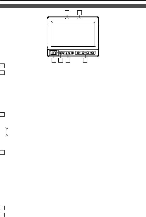
Front panel
5 6
|
1 |
FUNCTION |
|
FOCUS-R |
|
POWER |
2 |
3 |
|
|
|
INPUT MENU |
|
|
ENTER |
PEAK/ |
CONT/ |
|
|
|
|
PHASE |
CHROMA BRIGHT B.LIGHT |
1 |
2 |
3 |
4 |
1POWER switch/lamp
This switches the power supply ON/OFF. When the power is ON, the LED (green) lights up.
2INPUT SELECT button
This selects the signal input line. Each time the button is pressed, the input changes in the following order: YPBPR → VF-YPBPR/VF-VIDEO → VIDEO → SDI.
YPBPR |
: Analog component input |
VF-YPBPR / VF-VIDEO 1 |
: Viewfinder input |
VIDEO |
: Video input |
SDI 2 |
: Serial digital interface input (compatible with HD/SD) |
• The input line when the power supply is switched ON is the one that was selected the last time the power was switched OFF. The INPUT menu settings can be used to skip input lines that are not used.
• When the control lock is on, input lines cannot be selected.
1 The menu is used to set either YPBPR or VIDEO for the viewfinder input.2 Can only be selected when the separately sold BT-YA80G is installed.
3MENU and FUNCTION buttons
These are used for menu display, selecting settings and adjustments, and for carrying out the items selected in the menu.
MENU |
: Push to display or exit the menu, or to return to the previous menu screen. |
/ FUNCTION1 |
: Push to move the cursor down and select an item. |
|
In addition, FUNCTION1 carries out the item selected in the menu. |
/ FUNCTION2 |
: Push to move the cursor up and select an item. |
In addition, FUNCTION2 carries out the item selected in the menu. ENTER / FUNCTION3 : Push to confirm a setting, or to display a submenu.
In addition, FUNCTION3 carries out the item selected in the menu.
• When the control lock is on, the key mark appears and FUNCTION operations cannot be executed.
4Picture adjusting knobs/lamps
PEAK [PEAKING] 0 - 30(0) / PHASE 0 - 60(30)
CHROMA 0 - 60(30) / FOCUS-R(→page 27) 0 - 30(25) BRIGHT 0 - 60(30)
CONT [CONTRAST] 0 - 60(50) / B.LIGHT [BACKLIGHT] 0 - 60(60) ( ) denotes factory preset values
A rotating knob that can be pushed to operate. When the picture adjusting knob is pressed, its status is displayed and adjustment becomes possible. The setting values are saved by pushing the knob again.
When values are changed from the factory preset values, the LEDs to the side of knobs (amber) light.
The setting values are loaded when the monitor’s power is switched ON. The setting values are saved when the knob is pushed, or when 10 seconds pass after changing the settings. However, operating changes cannot be made in the following cases.
•When the control lock is on, the key mark appears and setting values cannot be changed.
•Only items selected in the menu can be adjusted for PEAK/PHASE and CONT/B. LIGHT.
•When the MONO function is ON, PHASE and CHROMA operations are disabled.
•FOCUS-R is enabled during operations of the FOCUS-IN-RED function.
•During BLUE ONLY, the PEAK/PHASE knob functions as PHASE.
5R-TALLY (red)
Can be lit by a control signal from a GPI/camera.
6G-TALLY (green)
Can be lit by a control signal from a GPI/camera.
7
Controls and Their Functions (continued)
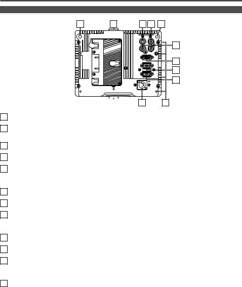
Rear panel
7 17
|
|
|
|
|
|
|
|
|
|
|
|
|
|
|
|
|
|
|
|
|
|
|
|
|
|
|
|
|
|
|
|
|
|
|
|
|
|
|
|
|
|
|
|
|
|
|
|
|
|
|
|
|
|
|
|
|
|
|
|
|
|
|
|
|
18 |
|
16 |
|
15 |
|
|
17 |
|
||||
|
8 |
9 |
7 |
SDI |
VIDEO/ |
|
|
(OPTION) |
|
Y |
|
PR |
|
PB |
10 |
|
|
|
|
VF |
|
|
|
GPI |
|
|
11 |
RS-232C |
|
|
12 |
|
|
DC IN |
13 |
14 |
|
18 |
|
7REAR TALLY (red)
Can be lit by a control signal from a GPI/camera.
8SDI (HD/SD) input terminal (BNC) - option
This is the SDI input terminal. (Compatible with HD/SD automatic switching)
• If you want this input, contact the vendor where you purchased the unit.
9VIDEO/Y input terminal (BNC)
This is the VIDEO signal (component signal) input terminal/Y input terminal.
10PBPR input terminal (BNC)
This is the PBPR signal (analog component signal) input terminal.
11VF terminal (D-SUB, 15 pins)
This terminal connects to the VF (viewfinder) terminal of broadcasting and business cameras made by Panasonic.
The unit can be used as the viewfinder for such a camera.
12GPI input terminal (D-SUB, 9 pins)
External control is possible by using a GPI signal.
13RS-232C terminal (D-SUB, 9 pins)
External control is possible by using an RS-232C interface.
14DC IN terminal (XLR, 4 pins)
This is the external DC power supply input terminal.
When a DC power supply is connected concurrently with the battery, the external power input takes precedence.
15Light control switch
This is not used on this monitor.
16Battery holder
This holder is used with a battery made by Anton/Bauer.
17Screw holes for tripod fixing
There are two screw holes on both the top and bottom for fixing the unit to a tripod (compatible with 3/8-16UNC). In addition, removable screw spacers are installed in one of the screw holes on the bottom of the unit, which are compatible with 1/4-20UNC screws. Use the size that matches the diameter of the tripod’s fixing screw.
18Screw holes for fixing
There are four screw holes (M3) for fixing the mounter on the rear of the unit, two each on the left and right.
8

Supplying the power
An Anton/Bauer or V-mount type of battery pack or an external DC power supply can be used to power this monitor.
Using the Anton/Bauer type battery pack
1. Install the Anton/Bauer type of battery pack.
Battery pack
2.Insert the battery pack and slide it in the direction of the arrow.
Release  lever
lever
<Reference>
To remove the battery pack, slide it in the opposite direction to the one in which it was attached while keeping the release lever on the battery holder pulled down all the way.
Using a V-mount type battery pack
CAUTION:
These servicing instructions are for use by qualified service personnel only. To reduce the risk of electric shock, do not perform any servicing other than that contained in the operating instructions unless you are qualified to do so.
1. Remove the battery holder.
Battery holder
2. Install the accessory battery mount terminal block.
Battery mount terminal block
3.Fix the V-mount type battery holder with four screws (length 8 mm (5/16 inch)) supplied with the holder, and then fasten the two screws on the terminal section.
This connector is not used.

V-mount type battery holder
9
Supplying the power (continued)
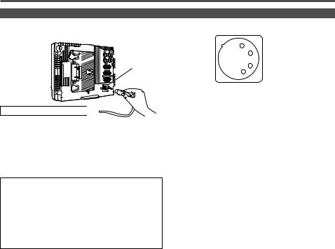
Using an external DC power supply
1. Connect the external DC power supply to the DC IN DC IN socket socket on this unit.
4
DC IN socket |
External DC power supply 

2.Turn “ON” the external DC power supply switch. (Where the external DC power supply has a power switch)
3.Turn “ON” the POWER switch on this unit.
If an external DC power supply is used, then check the ratings of the external DC power supply so that they are compatible with those of this unit.
Check the pin arrangements of the DC output terminal of the external DC power supply and those of the DC IN socket of this unit so that their polarities are correctly arranged.
If +12 V are supplied to the unit’s GND terminal by mistake, this may cause fire or injury.
3 |
1: GND |
|
|
2 |
4: +12 V |
1
<Notes>
•Use a shield cable with a length of 2 m (6.56 feet) or less for the DC cable. Use of cords any longer than 2 m (6.56 feet) may result in noise appearing on the screen.
•If the battery pack and an external DC power supply are connected simultaneously, then the external DC power supply will have priority.
If the external DC power supply is used, then the battery pack may be fitted or removed.
•If an external DC power supply is used, then make sure that the external DC power supply is first turned ON, then this unit is turned ON. If they are turned ON in the reverse order, then this unit may malfunction, because the output voltage of the external DC power supply will gradually increase.
•Input voltage that above the specification is not displayed accurately.
10
VF Function
The unit can be connected to broadcasting and business cameras made by Panasonic and used as a VF (viewfinder).
VF cable (Option)
DC cable (Option)
BT-LH80W
VF cable (Option) Part number: BT-CS80G
Camera platform 2 (commercially available)
Camera side
VF terminal
Camera side

 DC OUT terminal

 (1.5 A output)
DC cable 1 (Option. Included with the BT-CS80G.)
1 Broadcasting and business camera-recorders compatible with a DC power supply (output current of 1.5 A) AJ-HDC27H
AJ-HDX900 AJ-HPX2000 / 2100 AG-HPX500 / 502
Other cameras or camera-recorders cannot be used because they have an output current of 1 A or 0.1 A. Use a battery or external DC power supply.
Contact your vendor for details of broadcasting and business camera-recorders that will be launched in the future.
2 Use a camera platform that can fully withstand the weight of the unit (1.5 kg (3.3 lb)).
11
How to Use the On Screen Menu
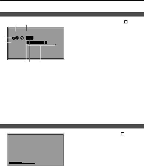
Six types of information are displayed on the screen: the operating status display, picture adjusting knob status, sharpness display, function display, DC power supply voltage display, battery level display and menu display.
Operating status display
1 2
7 |
YPBPR 1080/60I |
|
P-P |
|
|
6 |
DC14.0V |
50% |
5 4 |
3 |
1.The selected input line (→ page 7, 2 )
•YPBPR, VF-YPBPR/VF-VIDEO, VIDEO, SDI
2.Signal format
•The display status can be set in “STATUS DISPLAY” in the “SYSTEM CONFIG” menu (→ page 21).
•If “UNSUPPORT SIGNAL” is displayed, then either the current input signal is not supported or the “INPUT SELECT” menu setting needs to be changed.
•When “NO SIGNAL” is displayed, there is no input signal.
3.Battery level display
•When an Anton/Bauer type digital battery is used, battery level is displayed using a block count ( ) and percentage.
4.Various displays (PIXEL TO PIXEL mode)
•Displayed when the picture display is PIXEL TO PIXEL.
5.Various displays (warning of improper operation status for the camera settings)
•Displayed when there is an improper operation status relative to the camera settings.
6.DC power supply voltage display
•DC power supply voltage is displayed.
7.Various displays (lock setting)
•Displayed when front operations are locked (→ page 30).
<Note>
“UNSUPPORT SIGNAL” and “NO SIGNAL” may not be displayed correctly.
Picture adjusting knob status
Picture adjusting knob (→ page 7, 4 )
• This knob can be rotated and pushed.
• The status display appears when the knob is pushed. The display disappears when the knob is pushed again, or if the knob is not operated for 10 seconds.
• The settings can be adjusted while this display is shown, but the settings cannot be adjusted after the
display disappears.
[PHASE] 32
Status display: PEAKING or PHASE
CHROMA or FOCUS-IN-RED BRIGHT
CONTRAST or BACKLIGHT
12
 Loading...