


Operating Instructions
LCD Video Monitor
Model BT- 


 P
P
Before operating this product, please read the instructions carefully and save this manual for future use.
S0805M1095 -H D |
ENGLISH |
Printed in Japan VQT0U69-1

g THIS EQUIPMENT MUST BE GROUNDED
To ensure safe operation, the three-pin plug must be inserted only into a standard three-pin power outlet which is effectively grounded through normal household wiring. Extension cords used with the equipment must have three cores and be correctly wired to provide connection to the ground. Wrongly wired extension cords are a major cause of fatalities. The fact that the equipment operates satisfactorily does not imply that the power outlet is grounded or that the installation is completely safe.
For your safety, if you are in any doubt about the effective grounding of the power outlet, please consult a qualified electrician.
CAUTION:
THE AC RECEPTACLE (MAINS SOCKET OUTLET) SHALL BE INSTALLED NEAR THE EQUIPMENT AND SHALL BE EASILY ACCESSIBLE.
TO COMPLETELY DISCONNECT THIS EQUIPMENT FROM THE AC MAINS, DISCONNECT THE POWER CORD PLUG FROM THE AC RECEPTACLE.
WARNING:
•TO REDUCE THE RISK OF FIRE OR SHOCK HAZARD, DO NOT EXPOSE THIS EQUIPMENT TO RAIN OR MOISTURE.
•TO REDUCE THE RISK OF FIRE OR SHOCK HAZARD, KEEP THIS EQUIPMENT AWAY FROM ALL LIQUIDS. USE AND STORE ONLY IN LOCATIONS WHICH ARE NOT EXPOSED TO THE RISK OF DRIPPING OR SPLASHING LIQUIDS, AND DO NOT PLACE ANY LIQUID CONTAINERS ON TOP OF THE EQUIPMENT.
indicates safety information.
2

For Your Safety (continued)
FCC NOTICE (USA)
Declaration of Conformity
Model Number: |
BT-LH1700WP |
Trade Name: |
PANASONIC |
Responsible Party: |
Panasonic Corporation of North America |
|
One Panasonic Way, Secaucus, NJ07094 |
Support contact: |
Panasonic Broadcast & Television Systems Company |
|
1-800-524-1448 |
This device complies with Part 15 of FCC Rules. Operation is subject to the following two conditions:
(1)This device may not cause harmful interference, and (2) this device must accept any interference received, including interference that may cause undesired operation.
To assure continued compliance, follow the attached installation instructions and do not make any unauthorized modifications.
CAUTION:
This equipment has been tested and found to comply with the limits for a class B digital device, pursuant to Part 15 of the FCC Rules. These limits are designed to provide reasonable protection against harmful interference in a residential installation. This equipment generates, uses, and can radiate radio frequency energy, and if not installed and used in accordance with the instructions, may cause harmful interference to radio communications. However, there is no guarantee that interference will not occur in a particular installation. If this equipment does cause harmful interference to radio or television reception, which can be determined by turning the equipment off and on, the user is encouraged to try to correct the interference by one of the following measures:
•Reorient or relocate the receiving antenna.
•Increase the separation between the equipment and receiver.
•Connect the equipment into an outlet on a circuit different from that to which the receiver is connected. •Consult the dealer or an experienced radio/TV technician for help.
The user may find the booklet “Something About Interference” available from FCC local regional offices helpful.
FCC Warning:
To assure continued FCC emission limit compliance, the user must use only shielded interface cables when connecting to host computer or peripheral devices. Also, any unauthorized changes or modifications to this equipment could void the user’s authority to operate this device.
IMPORTANT SAFETY INSTRUCTIONS
1)Read these instructions.
2)Keep these instructions.
3)Heed all warnings.
4)Follow all instructions.
5)Do not use this apparatus near water.
6)Clean only with dry cloth.
7)Do not block any ventilation openings. Install in accordance with the manufacturer’s instructions.
8)Do not install near any heat sources such as radiators, heat registers, stoves, or other apparatus (including amplifiers) that produce heat.
9)Do not defeat the safety purpose of the polarized or grounding-type plug. A polarized plug has two blades with one wider than the other. A grounding-type plug has two blades and a third grounding prong. The wide blade or the third prong are provided for your safety. If the provided plug does not fit into your outlet, consult an electrician for replacement of the obsolete outlet.
10)Protect the power cord from being walked on or pinched particularly at plugs, convenience receptacles, and the point where they exit from the apparatus.
11)Only use attachments/accessories specified by the manufacturer.
12)Use only with the cart, stand, tripod, bracket, or table specified by the manufacturer, or sold
with the apparatus. When a cart is used, use caution when moving the cart/apparatus combination to avoid injury from tip-over.
13) Unplug this apparatus during lightning storms or when unused for long periods of time.
14)Refer all servicing to qualified service personnel. Servicing is required when the apparatus
has been damaged in any way, such as power-supply cord or plug is damaged, liquid has been spilled or objects have fallen into the apparatus, the apparatus has been exposed to rain or moisture, does not operate normally, or has been dropped.
3

Precautions for Use
•The liquid crystal portion is manufactured with highly precise technology. It includes over 99.99% effective pixels, but 0.01% or less of the pixels are either missing, or have fixed lighting (red, blue, green). This is not a sign of malfunction.
•The liquid crystal protection panel is a specially manufactured component. Wiping it with a hard cloth, or rubbing it vigorously will scratch the surface.
•If a still image is displayed for a long time, it may cause temporary generation of afterimage (phosphor burn-in). (However, these afterimages disappear when ordinary moving images are displayed for a while.)
•The response speed and brightness of liquid crystal vary with ambient temperatures.
•Consult with the authorized service person for the installation.
Be sure to consult with the service person about the installation. Make sure that the wall or celling is strong enough to endure the weight of this unit including the mount fittings. If not strong enough, it may cause accidents such as falling off of the unit and injury.
•Do not install the unit in a place exposed to the direct sunlight. It may otherwise deteriorate the cabinet or damage the liquid crystal screen.
Contents
For Your Safety . . . . . . . . . . . . . . . . . . . . . . . . . . . . |
2 |
Precautions for Use . . . . . . . . . . . . . . . . . . . . . . . . |
4 |
Standard accessories . . . . . . . . . . . . . . . . . . . . . . |
. 4 |
Optional units . . . . . . . . . . . . . . . . . . . . . . . . . . . . . . |
4 |
Outline . . . . . . . . . . . . . . . . . . . . . . . . . . . . . . . . . . . . |
5 |
Dimensions . . . . . . . . . . . . . . . . . . . . . . . . . . . . . . . . |
5 |
Controls and Their Functions . . . . . . . . . . . . . . . . . |
6 |
Video monitor unit ................................................... |
6 |
Front panel ............................................................. |
7 |
Rear panel.............................................................. |
8 |
Power Supply. . . . . . . . . . . . . . . . . . . . . . . . . . . . . . . |
9 |
How to Use the On Screen Menu . . . . . . . . . . . . . . |
10 |
User Data . . . . . . . . . . . . . . . . . . . . . . . . . . . . . . . . |
12 |
Main Menu . . . . . . . . . . . . . . . . . . . . . . . . . . . . . . . |
13 |
Menu configuration............................................... |
13 |
MARKER .............................................................. |
14 |
Types of MARKER................................................ |
15 |
VIDEO CONFIG ................................................... |
16 |
SYSTEM CONFIG................................................ |
17 |
GPI ....................................................................... |
20 |
INPUT SELECT.................................................... |
21 |
AUDIO ................................................................... |
22 |
CONTROL............................................................ |
22 |
REMOTE Specifications . . . . . . . . . . . . . . . . . . . . 23 How to Attach the Rack mounting . . . . . . . . . . . . . 27 Error/Warning Displays. . . . . . . . . . . . . . . . . . . . . . 27 Maintenance. . . . . . . . . . . . . . . . . . . . . . . . . . . . . . 27 Maintenance Inspections . . . . . . . . . . . . . . . . . . . 28 Specifications . . . . . . . . . . . . . . . . . . . . . . . . . . . . 28
Standard accessories
Power cord x 1 |
Screw x 1 |
Power cord hook x 1 |
|
Optional units
Rack-mounting adaptors BT-MA1710G (Fitting instructions J page 27)
Embedded Audio Unit BT-YAE1700G (Fitting instructions J Installation Guide included)
4
Outline
The BT-LH1700W liquid crystal monitor was designed especially for broadcasting service and business use. It is equipped with a high performance 17.1-inch wide liquid crystal display panel.
g High performance liquid crystal panel
This monitor achieves outstanding color reproduction, a wide viewing angle, and high-speed response.
g Immediate image output of input signals
The time-lag caused by IP field unit conversion*1 has been eliminated, and the delay from input until image output has been suppressed to the absolute minimum.
*1 Conversion from interlace to progressive scanning.
gMulti-format image compatability
•This monitor is equipped with SDI (HD/SD compatible), VIDEO, Y/C, YPBPR/RGB input jacks.
•It supports both NTSC and PAL TV broadcast systems.
g Screen display
You can divide the screen into two windows, and compare the windows using the same input terminal and same format. Furthermore, you can display a still image or WFM on one of the windows (Jpage 18 “SUB WINDOW”, page 19 “About the SUB WINDOW”).
g REMOTE control
Depending on the intended use of the monitor, you can select between parallel remote control (GPI) and serial remote control (RS232C) (Jpage 23 – 26).
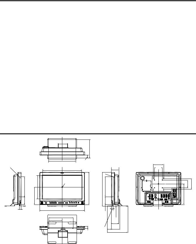
Dimensions |
|
|
|
|
|
|
|
|
|
|
Unit : mm (inches) |
|
|
|
|
|
|
|
|
|
|
|
|
|
|
178(7.0) |
|
|
|
|
|
|
|
|
260(10.2) |
30(1.2) |
|
|
|
|
100(3.9) |
|
|
|
|
|
|
|
|
|
|
|
||
2 |
(Opening) |
|
|
|
|
|
M4 |
72 |
75(3.0) |
|
- |
|
374.5(14.7) |
(Opening) |
|
|
|
|
(2.8) |
|
|
M4 |
|
|
|
|
|
|
|
|||
|
|
|
|
|
|
|
|
|
|
|
190(7.5) |
225.5(8.9) |
|
309(12.2) |
323.5(12.7) |
190(7.5) |
2- |
|
|
100(3.9) |
|
Center |
|
|
75(3.0) |
|||||||
|
|
|
|
|
|
|
|
|
|
|
75(3.0) |
166.5(6.6) |
|
|
|
|
75(3.0) |
|
14.5(0.6) |
197(7.8) |
|
|
|
233(9.2) |
|
|
|
15.1(0.6) |
|
|
|
|
16(0.6) |
|
430(16.9) |
|
|
|
|
|
|
|
|
|
280(11.0) |
|
|
|
|
|
|
|
|
|
|
|
|
|
|
|
|
|
|
|
|
|
128(5.0) |
|
|
|
|
|
|
70 |
|
|
|
|
|
|
|
|
|
|
(2.8) |
|
|
|
|
|
|
|
16(0.6) |
40 |
81.1 |
|
|
|
|
|
|
|
|
(1.6) |
(3.2) |
|
|
||
|
|
|
20.5 |
(0.8) |
|
|
|
|
||
|
|
|
|
|
|
198(7.8) |
|
|
||
|
|
|
|
|
|
|
|
|
|
|
When installing the monitor in one place permanently, we recommend that you fix the monitor in place using the screw holes in the lower part of the stand.
5

Controls and Their Functions
Video monitor unit
Front view
Front panel (J page 7)
Rear view
Fan
An embedded audio unit (BT-YAE1700G) can be attached (J Installation Guide included).
Rear panel (J page 8)
Power supply [you can switch between AC and DC (J page 9)]
6
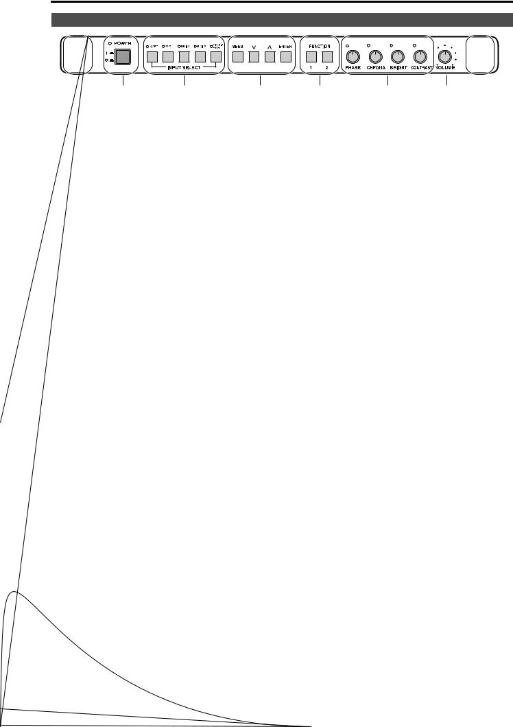
Front panel
POWER switch
This switches the power supply ON/OFF. When the power is ON, the LED (green) lights up.
INPUT SELECT button
This selects the signal input line. The green LED light above the button indicates the selected input signal.
VIDEO |
: |
Video input |
Y/C |
: |
Y/C input |
SDI1 |
: Serial digital interface input (HD/SD compatible) |
|
SDI2 |
: Serial digital interface input (HD/SD compatible) |
|
YPBPR/RGB |
: |
Analog component (YPBPR) or RGB input. Also compatible with PC input RGB. |
*When using PC Input, select “RGB-COMP.” from “YPBPR/RGB” in the “INPUT SELECT” menu (Jpage 21).
*The monitor retains the input signal settings selected from the last time the monitor was swiched ON or OFF.
MENU button
This is used for menu display, selecting settings, and adjustments.
MENU : Push to display or exit the menu, and to return to the previous menu screen.
,: Push to move the cursor up or down, or to select an item.
ENTER : Push to confirm a setting, and to display a submenu.
FUNCTION button
FUNCTION 1 : Carries out the item selected in the menu.
FUNCTION 2 : Carries out the item selected in the menu.
Picture adjusting knob
PHASE |
0 – 60 (30) |
CHROMA |
0 – 60 (30) |
BRIGHT |
0 – 60 (30) |
CONTRAST |
0 – 60 (50) |
( ) denotes factory preset values
A rotating knob that can be pushed to operate. You can display and adjust the menu settings by pushing the knob. The setting values are saved by pushing the knob again.
When values are changed from the factory preset values, the LED above the knob (amber) lights.
The setting values are loaded when the monitor’s power is switched ON. The setting values are saved when the knob is pushed, or when 10 seconds pass after changing the settings. However, operating changes cannot be made in the following cases.
*When the control lock is on, the key mark appears and setting values cannot be changed (J page 22).
*When the MONO function is ON (J page 16), [PHASE] and [CHROMA] operations are disabled.
*When using “RGB-COMP.” input, [PHASE] and [CHROMA] operations are disabled.
*While operating HV DELAY (J page 17) (when set to any other setting than OFF), [BRIGHT] operation is disabled.
Volume knob
You can adjust the speaker volume by rotating the volume knob.
Speaker
Audio input from the AUDIO input terminal or SDI terminal (embedded audio) can be heard.
*The BT-YAE1700G embedded audio unit (optional) must be attached to hear audio through embedded audio.
7
Controls and Their Functions (continued)
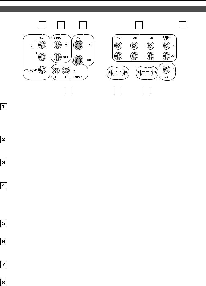
Rear panel
|
1 |
|
|
|
|
|
2 |
|
|
|
|
|
|
|
|
3 |
|
|
|
|
|
|
|
|
|
|
|
|
4 |
|
|
|
|
|
|
|
|
|
5 |
||||||||||||||||||||
|
|
|
|
|
|
|
|
|
|
|
|
|
|
|
|
|
|
|
|
|
|
|
|
|
|
|
|
|
|
|
|
|
|
|
|
|
|
|
|
|
|
|
|
|
|
|
|
|
|
|
|
|
|
|
|
|
|
|
|
|
|
|
|
|
|
|
|
|
|
|
|
|
|
|
|
|
|
|
|
|
|
|
|
|
|
|
|
|
|
|
|
|
|
|
|
|
|
|
|
|
|
|
|
|
|
|
|
|
|
|
|
|
|
|
|
|
|
|
|
|
|
|
|
|
|
|
|
|
|
|
|
|
|
|
|
|
|
|
|
|
|
|
|
|
|
|
|
|
|
|
|
|
|
|
|
|
|
|
|
|
|
|
|
|
|
|
|
|
|
|
|
|
|
|
|
|
|
|
|
|
|
|
|
|
|
|
|
|
|
|
|
|
|
|
|
|
|
|
|
|
|
|
|
|
|
|
|
|
|
|
|
|
|
|
|
|
|
|
|
|
|
|
|
|
|
|
|
|
|
|
|
|
|
|
|
|
|
|
|
|
|
|
|
|
|
|
|
|
|
|
|
|
|
|
|
|
|
|
|
|
|
|
|
|
|
|
|
|
|
|
|
|
|
|
|
|
|
|
|
|
|
|
|
|
|
|
|
|
|
|
|
|
|
|
|
|
|
|
|
|
|
|
|
|
|
|
|
|
|
|
|
|
|
|
|
|
|
|
|
|
|
|
|
|
|
|
|
|
|
|
|
|
|
|
|
|
|
|
|
|
|
|
|
|
|
|
|
|
|
|
|
|
|
|
|
|
|
|
|
|
|
|
|
|
|
|
|
|
|
|
|
|
|
|
|
|
|
|
|
|
|
|
|
|
|
|
|
|
|
|
|
|
|
|
|
|
|
|
|
|
|
|
|
|
|
|
|
|
|
|
|
|
|
|
|
|
|
|
|
|
|
|
|
|
|
|
|
|
|
|
|
|
|
|
|
|
|
|
|
|
|
|
|
|
|
|
|
|
|
|
|
|
|
|
|
|
|
|
|
|
|
|
|
|
|
|
|
|
|
|
|
|
|
|
|
|
|
|
|
|
|
|
|
|
|
|
|
|
|
|
|
|
|
|
|
|
|
|
|
|
|
|
|
|
|
|
|
|
|
|
|
|
|
|
|
|
|
|
|
|
|
|
|
|
|
|
|
|
|
|
|
|
|
|
|
|
|
|
|
|
|
|
|
|
|
|
|
|
|
|
|
|
|
|
|
|
|
|
|
|
|
|
|
|
|
|
|
|
|
|
|
|
|
|
|
|
|
|
|
|
|
|
|
|
|
|
|
|
|
|
|
|
|
|
|
|
|
|
|
|
|
|
|
|
|
|
|
|
|
|
|
|
|
|
|
|
|
|
|
|
|
|
|
|
|
|
|
|
|
|
|
|
|
|
|
|
|
|
|
|
|
|
|
|
|
|
|
|
|
|
|
|
|
|
|
|
|
|
|
|
|
|
|
|
|
|
|
|
|
|
|
|
|
|
|
|
|
|
|
|
|
|
|
|
|
|
|
|
|
|
|
|
|
|
|
|
|
|
|
|
|
|
|
|
|
|
|
|
|
|
|
|
|
|
|
|
|
|
|
|
|
|
|
|
|
|
|
|
|
|
|
|
|
|
|
|
|
|
|
|
|
|
|
|
|
|
|
|
|
|
|
|
|
|
|
|
|
|
|
|
|
|
|
|
|
|
|
|
|
|
|
|
|
|
|
|
|
|
|
|
|
|
|
|
|
|
|
|
|
|
|
|
|
|
|
|
|
|
|
|
|
|
|
|
|
|
|
|
|
|
|
|
|
|
|
|
|
|
|
|
|
|
|
|
|
|
|
|
|
|
|
|
|
|
|
|
|
|
|
|
|
|
|
|
|
|
|
|
|
|
|
|
|
|
|
|
|
|
|
|
|
|
|
|
|
|
|
|
|
|
|
|
|
|
|
|
|
|
|
|
|
|
|
|
|
|
|
|
|
|
|
|
|
|
|
|
|
|
|
|
|
6 |
|
7 |
|
8 |
|
SDI (HD/SD) terminal (BNC) |
|
|
|
|
|
||
IN1 |
: This is the SDI input terminal (compatible with HD/SD automatic switching). |
||||||
IN2 |
: This is the SDI input terminal (compatible with HD/SD automatic switching). |
||||||
SWITCHED OUT |
: This is the active through-out terminal for the SDI input signal being displayed on the screen. |
||||||
*SDI active through-out is only outputted when [SDI1] or [SDI2] is selected using the [INPUT SELECT] buttons. It is not outputted when anything other than SDI is selected.
VIDEO terminal (BNC)
IN |
: This is the VIDEO signal (composite signal) input terminal. |
OUT |
: This is the input signal through-out terminal. |
Y/C terminal |
|
IN |
: This is the Y/C signal (S-video signal) input terminal. |
OUT |
: This is the input signal through-out terminal. |
YPBPR/RGB terminal (BNC)
IN |
: This is the YPBPR/RGB signal input terminal. |
OUT |
: This is the input signal through-out terminal. |
*When using the RGB signal, you can also connect the external synchronizing signal to the SYNC/HD terminal. When using a PC RGB signal, connect the horizontal synchronizing signal to the SYNC/HD terminal, and the vertical synchronizing signal to the VD terminal.
VD IN input terminal
This is the vertical synchronizing signal (VD) input terminal used when connecting to a PC RGB signal.
AUDIO input terminal (Pin terminal)
This is the common audio input terminal for all video input terminals.
*When an embedded audio unit BT-YAE1700G (optional) is attached, SDI input audio is automatically selected by selecting [SDI1] or [SDI2] with [INPUT SELECT].
GPI input terminal (D-SUB 9-pin)
External control is possible by using a GPI signal.
RS232C input terminal (D-SUB 9-pin)
External control is possible by using a RS232C signal.
8
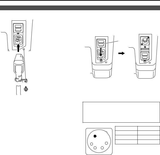
Power Supply
Connecting and fixing the power cord
1. Attach the power cord to the monitor unit.
Using the power cord hook and the screw, attach the power cord to the monitor unit.
 Power cord
 Power cord hook
 Screw
Screw
2. Connect the power cord to the power outlet.
g When using external DC power (DC11V–17V)
You can slide open the power cover, and switch from AC input to external DC input. (When shipped from the factory, the power cover is up, and AC input is selected.)
Power cover
Please note the following
If the power cover has been removed or opened, do not use the monitor with the power supply connected to both the AC input and external DC input terminals.
When using external DC power (DC11V–17V), check the external DC input terminal pin signal, and use the correct polarity. If a +12V power supply is accidentally connected to the GND terminal, this could cause a fire or personal injury.
|
|
Pin number |
Signal |
|
|
1 |
GND |
|
|
2, 3 |
— |
1 |
4 |
4 |
+12V |
2 |
3 |
|
|
External DC input terminal
9
 Loading...