Orion Car Audio 275XTR, 250XTR, 2150XTR User Manual

Technical Brief :
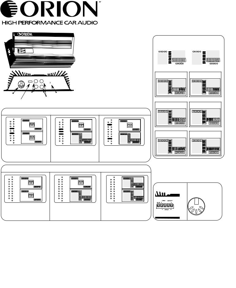
How to properly set a 2 channel XTR or HCCA amp with X-over (removable top plate). Included amps: 250XTR, 275XTR, 2150XTR, 225HCCA, 250HCCA.
Crossover:
The XTR/HCCA amp includes a SLF-1 crossover
module. The card is adjustable for High pass or
Low pass (see diagram). See diagram below for
installation instructions. If the SLF-1 card is not
used, a Bypass card must be put in it's place or the amp will not pass signal.
SLF-1 Crossover Card Set Up Chart
|
|
80hz High pass |
|
|
|
|
80hz Low pass |
|
||||||||
|
|
|
|
|
|
|
|
|
|
|
|
|
|
|
|
|
|
|
|
|
|
|
|
|
|
|
|
|
|
|
|
|
|
|
|
|
|
|
|
|
|
|
|
|
|
|
|
|
|
|
|
|
|
|
|
|
|
|
|
|
|
|
|
|
|
|
|
|
|
|
|
|
|
|
|
|
|
|
|
|
|
|
|
|
|
|
|
|
|
|
|
|
|
|
|
|
|
|
|
|
|
DIN |
L + R RCA |
GAIN |
INPUT |
INPUT |
L + R RCA |
|
|
Power on LED |
AUX OUT |
|
Jumper Configuration:
The configuration of jumpers at the left of the crossover cards determines the output of the amp. See the diagram below for set-up instructions. Configuration #1 is for stereo operation and Configuration #2 is for mono operation. To activate the AUXOUT, install the jumper as shown in configuration # 3. This will pass full range signal out.
Configuration for Input Jumpers
1 |
2 |
1 |
2 |
1 |
2 |
|
ON |
||||
|
|
ON |
|
ON |
|
1 |
2 |
|
|
|
|
|
ON |
|
|
|
|
Jumper configuration #1 |
Jumper configuration #2 |
Add these jumpers to |
|||
Stereo Output. |
Mono Output. |
Configuration 1 or 2 for |
|||
|
|
|
|
Full Range from Aux Out. |
|
Configuration of Crossover and Bypass Cards
1 |
2 |
1 |
2 |
|
|
ON |
|
ON |
|
1 |
2 |
|
|
|
|
ON |
|
|
|
2 Bypass cards |
(1) SLF-1 + (1) Bypass |
(2) SLF-1 Cards |
||
= no crossover |
= 12dB Slope |
= 24dB Slope |
||
120hz High pass
160hz High pass
200hz High pass
120hz Low pass
160hz Low pass
200hz Low pass
Input Voltage:
The Gain of the XTR/HCCA amplifier will accept up to 5v of input signal.
Speaker Plug |
DIN Plug Diagram |
|||||
Wiring Diagram |
||||||
|
|
|
|
|
||
|
|
|
|
1. |
-15 Volts |
|
|
|
|
|
2. |
Left Input |
|
|
1 |
|
5 |
3. |
Ground |
|
|
|
4. |
Right Input |
|||
|
2 |
|
4 |
|||
|
3 |
5. |
+15 Volts |
|||
|
|
|
||||
|
|
|
|
|||
AMP |
POWER |
Lowest Recommend |
Fuse Size |
S/N |
THD |
Frequency |
Dimensions |
|
Impedance in Stereo |
Response |
|||||||
|
|
|
|
|
|
|||
|
|
|
|
|
|
|
|
|
250XTR |
50 X 2 |
2ohm |
30 amp |
100dB |
0.02% |
6hz to 30Khz |
11" x 8.5" x 2.25" |
|
+/- 0.5dB |
||||||||
|
|
|
|
|
|
|
|
|
275XTR |
75 x 2 |
2ohm |
35 amp |
100dB |
0.02% |
6hz to 30Khz |
12" x 8.5" x 2.25" |
|
+/- 0.5dB |
||||||||
|
|
|
|
|
|
|
|
|
2150XTR |
150 x 2 |
2ohm |
60 amp |
100dB |
0.02% |
6hz to 30Khz |
18" x 8.5" x 2.25" |
|
+/- 0.5dB |
||||||||
|
|
|
|
|
|
|
||
|
|
|
|
|
|
|
|
|
225HCCA |
25 x 2 |
0.5ohm |
30 amp |
100dB |
0.02% |
6hz to 30Khz |
12" x 8.5" x 2.25" |
|
+/- 0.5dB |
||||||||
|
|
|
|
|
|
|
||
|
|
|
|
|
|
|
|
|
250HCCA |
50 x 2 |
1ohm |
60 amp |
100dB |
0.02% |
6hz to 30Khz |
18" x 8.5" x 2.25" |
|
+/- 0.5dB |
||||||||
|
|
|
|
|
|
|
|
For questions on this or any other Orion Products, call Technical Support at 1-480-705-5600.
 Loading...