


EN
FEATURES: MAIN UNIT
MULTI-CHANNEL IN-OUT
CABLE FREE THERMO-HYGROMETER
MODEL : EMR812HGN
USER’S MANUAL
INTRODUCTION
Congratulations on your purchase of the Multi-Channel In-Out Thermometer / Hygrometer (EMR812HGN) with a 433MHz cablefree thermo-hygro sensor.
Enclosed with this package is one (1) main display unit and one (1) cable-free remote thermo-hygro sensor unit.
The main unit has an extra-large multifunction 2-line LCD that shows recordings for indoor and outdoor temperatures, humidity, maximum and minimum recordings and trend indicators. The unit supports up to three 433MHz remote thermo-sensors or thermohygro sensors. A variety of additional sensors can be purchased separately.
In addition to monitoring maximum and minimum temperature and humidity readings, the unit also has an alarm that can be set to activate once readings exceed a given variance.
No wire installation is required between the main and remote units. As the EMR812HGN operates at 433MHz, it can be used in the U.S. and most places in Continental Europe.
1

EN |
A |
Extra large two-line Liquid Crystal Display (LCD) |
|
|
|||
|
|
Multifunction display showing temperature and humidity, |
|
|
|
max./min. memory, and trend indicators for the main unit and |
|
|
|
remote sensors. |
|
|
B |
CHANNEL button |
|
|
|
- |
Selects among different channels |
|
|
- |
Activates remote sensor scanning mode |
|
C |
IN/REMOTE |
|
|
|
- |
Selects between the main-unit display and a selected |
|
|
|
remote unit |
|
|
- |
Activates search mode |
|
D |
MEM/CLEAR button |
|
|
|
- |
Recalls the maximum or minimum temperature and |
|
|
|
humidity readings |
|
|
- |
Clears the maximum and minimum temperature and |
|
|
|
humidity memory of remote sensor channels or the main |
|
|
|
unit display |
|
E |
HI/LO button |
|
|
|
- |
Set the upper or lower temperature alarm limits of |
|
|
|
individual channels |
|
|
- |
Confirms alarm settings |
|
F |
|
button |
Sets the readings for the upper or lower temperature and humidity of individual channels
GAL ON/OFF button
Activates or deactivates alarm
HRESET
Returns all settings to default values and erases all memories
I° C/° F slide switch
Selects between degree Centigrade (° C) and Fahrenheit (° F)
JBattery compartment
Accommodates two AA-size batteries
KRetractable table stand
For standing the main unit on a flat surface
LRecessed Wall-mount hole
For mounting the main unit on a wall
FEATURES: REMOTE
THERMO-HYGRO SENSOR
ATwo-line LCD
Displays the current temperature and humidity monitored by the remote unit
BLED indicator
Flashes when the remote unit transmits a reading
C° C/° F slide switch
Selects between Centigrade (° C) and Fahrenheit (° F)
DChannel slide switch
Designates the remote unit Channel 1, Channel 2 or Channel 3
ERESET
Returns all settings to default values
FBattery compartment
Accommodates two AAA-size batteries
GBattery door
2
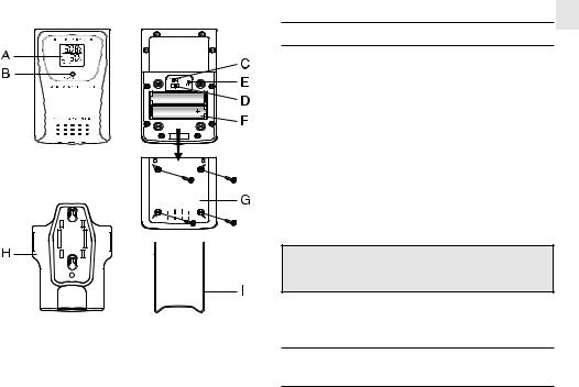
HWall-mount holder
Supports the remote unit in wall-mounting
IRemovable table stand
For standing the remote unit on a flat surface
EN
BEFORE YOU BEGIN
To ensure proper functioning of the EMR812HGN follow this setup procedure.
For best operation:
1.Assign different channels to different remote units.
2.Insert batteries for remote units before doing so for the main unit (see instructions for battery installation).
3.Place the main unit as close as possible next to the remote unit, reset the main unit after installing batteries. This will ensure easier synchronization between the transmission and reception of signals.
4.Position the remote unit and main unit within effective transmission range, which, in usual circumstances, is 20 to 30 meters.
Note that the effective range is vastly affected by the building materials and where the main and remote units are positioned. Try various set-ups for best result.
Though the remote units are weather proof, they should be placed away from direct sunlight, rain or snow.
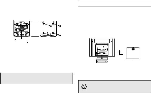
BATTERY AND CHANNEL
INSTALLATION: REMOTE UNIT
The remote thermo-hygro sensor unit uses two (2) UM-4 or “AAA” size alkaline batteries.
3
EN |
Follow these steps to install / replace batteries: |
||||||
|
|||||||
|
1. |
Remove the screws on the battery compartment. |
|||||
|
2. |
Select the channel number on the CHANNEL slide switch. |
|||||
|
3. |
Select the temperature display unit on the ° C/° F slide switch. |
|||||
|
|
|
|
|
|
|
|
|
|
|
|
|
|
|
|
|
|
|
|
|
|
|
|
|
|
|
|
|
|
|
|
|
|
|
|
|
|
|
|
|
|
|
|
|
|
|
|
|
|
|
|
|
|
|
|
4.Insert the batteries strictly according to the polarities shown therein.
5.Replace the battery compartment door and secure its screws.
Replace the batteries when the low-battery indicator of the particular channel lights up on the main unit. (Repeat the steps described in section “BEFORE YOU BEGIN”)
Note that once a channel is assigned to a remote unit, you can only change it by removing the batteries or resetting the unit.
BATTERY INSTALLATION: MAIN UNIT
The main unit uses two (2) UM-3 or “AA” size alkaline batteries.
Follow these steps to install / replace batteries:
1.Slide open the battery compartment door.
2.Insert the batteries strictly according to the polarities shown therein.
3.Replace the battery compartment door.
Replace the batteries when the low-battery indicator of the indoors temperature lights up. (Repeat the steps described in section “BEFORE YOU BEGIN”)
If not disposed of properly, batteries can be harmful.
Protect the environment by taking exhausted batteries ot authorized disposal stations.
4
 Loading...