


TX-SR703
Table of contents
 Loading...
E
n
AV Receiver
TX-SR803/803E
TX-SR703/703E
TX-SR8370
Instruction Manual
Thank you for purchasing an Onkyo AV Receiver.
Please read this manual thoroughly before making
connections and plugging in the unit.
Following the instructions in this manual will enable
you to obtain optimum performance and listening
enjoyment from your new AV Receiver.
Please retain this manual for future reference.
Contents
Introduction ..................................... 2
Connection .................................... 19
Turning On & First Time Setup..... 39
Basic Operation
Playing your AV components ....... 48
Using the Tuner............................ 49
Enjoying the Listening Modes ..... 60
Advanced Operation..................... 64
Troubleshooting ............................ 91
2
Important Safety Instructions
1. Read these instructions.
2. Keep these instructions.
3. Heed all warnings.
4. Follow all instructions.
5. Do not use this apparatus near water.
6. Clean only with dry cloth.
7. Do not block any ventilation openings. Install in
accordance with the manufacturer’s instructions.
8. Do not install near any heat sources such as radia-
tors, heat registers, stoves, or other apparatus
(including amplifiers) that produce heat.
9. Do not defeat the safety purpose of the polarized or
grounding-type plug. A polarized plug has two
blades with one wider than the other. A grounding
type plug has two blades and a third grounding
prong. The wide blade or the third prong are pro-
vided for your safety. If the provided plug does not
fit into your outlet, consult an electrician for
replacement of the obsolete outlet.
10. Protect the power cord from being walked on or
pinched particularly at plugs, convenience recepta-
cles, and the point where they exit from the appara-
tus.
11. Only use attachments/accessories specified by the
manufacturer.
12.
Use only with the cart, stand,
tripod, bracket, or table spec-
ified by the manufacturer, or
sold with the apparatus.
When a cart is used, use cau-
tion when moving the cart/
apparatus combination to
avoid injury from tip-over.
13. Unplug this apparatus during lightning storms or
when unused for long periods of time.
14. Refer all servicing to qualified service personnel.
Servicing is required when the apparatus has been
damaged in any way, such as power-supply cord or
plug is damaged, liquid has been spilled or objects
have fallen into the apparatus, the apparatus has
been exposed to rain or moisture, does not operate
normally, or has been dropped.
15. Damage Requiring Service
Unplug the apparatus from the wall outlet and refer
servicing to qualified service personnel under the
following conditions:
A. When the power-supply cord or plug is damaged,
B. If liquid has been spilled, or objects have fallen
into the apparatus,
C. If the apparatus has been exposed to rain or
water,
D. If the apparatus does not operate normally by
following the operating instructions. Adjust only
those controls that are covered by the operating
instructions as an improper adjustment of other
controls may result in damage and will often
require extensive work by a qualified technician
to restore the apparatus to its normal operation,
E. If the apparatus has been dropped or damaged in
any way, and
F. When the apparatus exhibits a distinct change in
performance this indicates a need for service.
16. Object and Liquid Entry
Never push objects of any kind into the apparatus
through openings as they may touch dangerous volt-
age points or short-out parts that could result in a
fire or electric shock.
The apparatus shall not be exposed to dripping or
splashing and no objects filled with liquids, such as
vases shall be placed on the apparatus.
Don’t put candles or other burning objects on top of
this unit.
17. Batteries
Always consider the environmental issues and fol-
low local regulations when disposing of batteries.
18. If you install the apparatus in a built-in installation,
such as a bookcase or rack, ensure that there is ade-
quate ventilation.
Leave 20 cm (8") of free space at the top and sides
and 10 cm (4") at the rear. The rear edge of the shelf
or board above the apparatus shall be set 10 cm (4")
away from the rear panel or wall, creating a flue-like
gap for warm air to escape.
WARNING:
TO REDUCE THE RISK OF FIRE OR ELECTRIC
SHOCK, DO NOT EXPOSE THIS APPARATUS
TO RAIN OR MOISTURE.
CAUTION:
TO REDUCE THE RISK OF ELECTRIC SHOCK,
DO NOT REMOVE COVER (OR BACK). NO
USER-SERVICEABLE PARTS INSIDE. REFER
SERVICING TO QUALIFIED SERVICE
PERSONNEL.
The lightning flash with arrowhead symbol, within an
equilateral triangle, is intended to alert the user to the
presence of uninsulated “dangerous voltage” within
the product’s enclosure that may be of sufficient
magnitude to constitute a risk of electric shock to
persons.
The exclamation point within an equilateral triangle is
intended to alert the user to the presence of important
operating and maintenance (servicing) instructions in
the literature accompanying the appliance.
WARNING
RISK OF ELECTRIC SHOCK
DO NOT OPEN
RISQUE DE CHOC ELECTRIQUE
NE PAS
OUVRIR
AVIS
PORTABLE CART WARNING
S3125A

3
Precautions
1. Recording Copyright—Unless it’s for personal use
only, recording copyrighted material is illegal with-
out the permission of the copyright holder.
2. AC Fuse—The AC fuse inside the unit is not user-
serviceable. If you cannot turn on the unit, contact
your Onkyo dealer.
3. Care—Occasionally you should dust the unit all
over with a soft cloth. For stubborn stains, use a soft
cloth dampened with a weak solution of mild deter-
gent and water. Dry the unit immediately afterwards
with a clean cloth. Don’t use abrasive cloths, thin-
ners, alcohol, or other chemical solvents, because
they may damage the finish or remove the panel let-
tering.
4. Power
WARNING
BEFORE PLUGGING IN THE UNIT FOR THE
FIRST TIME, READ THE FOLLOWING SEC-
TION CAREFULLY.
AC outlet voltages vary from country to country.
Make sure that the voltage in your area meets the
voltage requirements printed on the unit’s rear panel
(e.g., AC 230 V, 50 Hz or AC 120 V, 60 Hz).
Some models have a voltage selector switch for
compatibility with power systems around the world.
Before you plug in such a model, make sure that the
voltage selector is set to the correct voltage for your
area.
For North American & Australian models
Setting the [STANDBY/ON] switch to STANDBY
does not fully shutdown the unit. If you do not
intend to use the unit for an extended period,
remove the power cord from the AC outlet.
5. Never Touch this Unit with Wet Hands—Never
handle this unit or its power cord while your hands
are wet or damp. If water or any other liquid gets
inside this unit, have it checked by your Onkyo
dealer.
6. Handling Notes
• If you need to transport this unit, use the original
packaging to pack it how it was when you origi-
nally bought it.
• Do not leave rubber or plastic items on this unit
for a long time, because they may leave marks on
the case.
• This unit’s top and rear panels may get warm
after prolonged use. This is normal.
• If you do not use this unit for a long time, it may
not work properly the next time you turn it on, so
be sure to use it occasionally.
Memory Backup
The AV receiver uses a battery-less memory backup
system in order to retain radio presets and other settings
when it’s unplugged or in the case of a power failure.
Although no batteries are required, the AV receiver
must be plugged into an AC outlet in order to charge the
backup system. Once it has been charged, the AV
receiver will retain the settings for several weeks,
although this depends on the environment and will be
shorter in humid climates.
For British models
Replacement and mounting of an AC plug on the power
supply cord of this unit should be performed only by
qualified service personnel.
IMPORTANT
The wires in the mains lead are coloured in accordance
with the following code:
Blue: Neutral
Brown: Live
As the colours of the wires in the mains lead of this
apparatus may not correspond with the coloured mark-
ings identifying the terminals in your plug, proceed as
follows:
The wire which is coloured blue must be connected to
the terminal which is marked with the letter N or
coloured black.
The wire which is coloured brown must be connected to
the terminal which is marked with the letter L or
coloured red.
IMPORTANT
The plug is fitted with an appropriate fuse. If the fuse
needs to be replaced, the replacement fuse must
approved by ASTA or BSI to BS1362 and have the same
ampere rating as that indicated on the plug. Check for
the ASTA mark or the BSI mark on the body of the fuse.
If the power cord’s plug is not suitable for your socket
outlets, cut it off and fit a suitable plug. Fit a suitable
fuse in the plug.
For European Models
Declaration of Conformity
We,
ONKYO EUROPE
ELECTRONICS GmbH
LIEGNITZERSTRASSE 6,
82194 GROEBENZELL,
GERMANY
GROEBENZELL, GERMANY
ONKYO EUROPE ELECTRONICS GmbH
K. MIYAGI
declare in own responsibility, that the ONKYO product
described in this instruction manual is in compliance with the
corresponding technical standards such as EN60065,
EN55013, EN55020 and EN61000-3-2, -3-3.
4
Precautions—Continued
For U.S. models
FCC Information for User
CAUTION:
The user changes or modifications not expressly
approved by the party responsible for compliance could
void the user’s authority to operate the equipment.
NOTE:
This equipment has been tested and found to comply
with the limits for a Class B digital device, pursuant to
Part 15 of the FCC Rules. These limits are designed to
provide reasonable protection against harmful interfer-
ence in a residential installation.
This equipment generates, uses and can radiate radio
frequency energy and, if not installed and used in accor-
dance with the instructions, may cause harmful interfer-
ence to radio communications. However, there is no
guarantee that interference will not occur in a particular
installation. If this equipment does cause harmful inter-
ference to radio or television reception, which can be
determined by turning the equipment off and on, the
user is encouraged to try to correct the interference by
one or more of the following measures:
• Reorient or relocate the receiving antenna.
• Increase the separation between the equipment and
receiver.
• Connect the equipment into an outlet on a circuit dif-
ferent from that to which the receiver is connected.
• Consult the dealer or an experienced radio/TV techni-
cian for help.
For Canadian Models
NOTE: THIS CLASS B DIGITAL APPARATUS
COMPLIES WITH CANADIAN ICES-003.
For models having a power cord with a polarized plug:
CAUTION: TO PREVENT ELECTRIC SHOCK,
MATCH WIDE BLADE OF PLUG TO WIDE SLOT,
FULLY INSERT.
Modèle canadien
REMARQUE: CET APPAREIL NUMÉRIQUE DE
LA CLASSE B EST CONFORME À LA NORME
NMB-003 DU CANADA.
Sur les modèles dont la fiche est polarisée:
ATTENTION: POUR ÉVITER LES CHOCS ÉLEC-
TRIQUES, INTRODUIRE LA LAME LA PLUS
LARGE DE LA FICHE DANS LA BORNE CORRE-
SPONDANTE DE LA PRISE ET POUSSER
JUSQU’AU FOND.
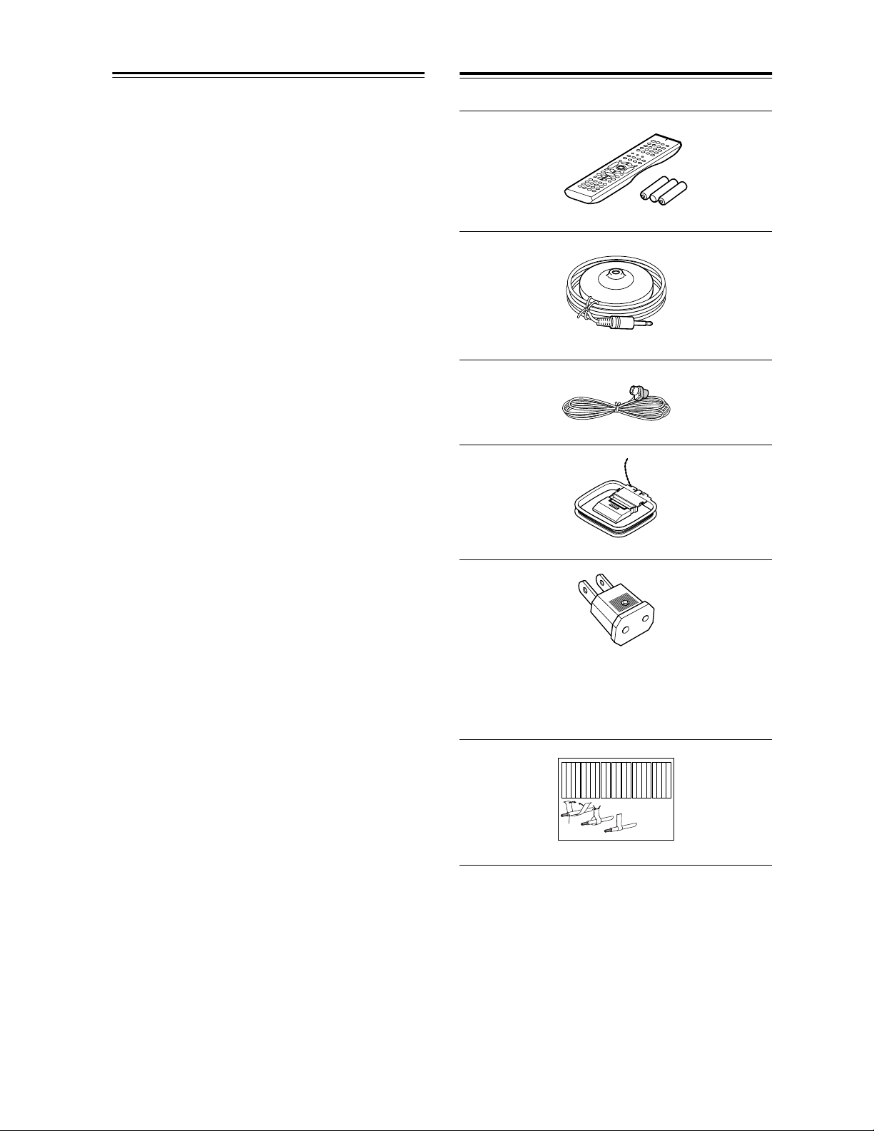
Supplied Accessories
Make sure you have the following accessories:
* In catalogs and on packaging, the letter at the end of the
product name indicates the color. Specifications and oper-
ation are the same regardless of color.
Remote controller and three batteries (AA/R6)
Speaker setup microphone
Indoor FM antenna
AM loop antenna
Power-plug adapter
Only supplied in certain countries. Use this adapter if
your AC outlet does not match with the plug on the AV
receiver’s power cord. (Adapter varies from country to
country.)
Speaker cable labels
Front
Left
Front
Left
SP-B/Zone 2
Left
SP-B/Zone 2
Left
Surround
Right
Surround
Right
Surround Back
Right
Surround Back
Right
Zone 2
Right
Zone 2
Right
Front
Left
Front
Left
SP-B/Zone 2
Left
SP-B/Zone 2
Left
Front
Right
Front
Right
SP-B/Zone 2
Right
SP-B/Zone 2
Right
Front
Right
Front
Right
SP-B/Zone 2
Right
SP-B/Zone 2
Right
Surround
Right
Surround
Right
Center
Center
Center
Center
Surround
Left
Surround
Left
Surround
Left
Surround
Left
Surround Back
Right
Surround Back
Right
Zone 2
Right
Zone 2
Right
Surround Back
Left
Surround Back
Left
Zone 2
Left
Zone 2
Left
Surround Back
Left
Surround Back
Left
Zone 2
Left
Zone 2
Left
1
2
3
Speaker Cable
5
Contents
Introduction
Important Safety Instructions ....................2
Precautions .................................................3
Supplied Accessories.................................4
Features .......................................................6
Getting to Know the AV Receiver..............7
Remote Controller.....................................13
Connection
Connecting Your Speakers ......................19
Connecting Antenna.................................22
Connecting Your Components ................24
About AV Connections ................................24
Connecting Audio and Video Signals
to the AV Receiver .................................... 25
Which Connections Should I Use?..............25
TV or Projector ............................................26
DVD player .................................................. 27
VCR or DVD Recorder for Playback ...........29
VCR or DVD Recorder for Recording.......... 30
Satellite, Cable, Set-top box,
or Other Video Source ..............................31
Camcorder, Games Console,
or Other Device.........................................32
CD Player .................................................... 33
Turntable .....................................................33
Cassette, CDR, MiniDisc,
or DAT Recorder.......................................34
Power Amplifier ...........................................34
Connecting Onkyo Components ..........35
Connecting Components with HDMI
(TX-SR803/803E Only) ............................. 36
Connecting the Power Cords of Other
Components..............................................38
Connecting the RS232 Port.........................38
Connecting the Power Cord ........................38
Turning On & First Time Setup
Turning On the AV Receiver ....................39
Turning On and Standby .............................39
First Time Setup........................................40
Automatic Speaker Setup............................40
HDMI Video Setup
(TX-SR803/803E Only) ............................. 43
Component Video Setup .............................44
Digital Audio Input Setup.............................45
Changing the Input Display .........................46
Minimum Speaker Impedance.....................46
TV Format Setup
(not North American models) .................... 47
AM Frequency Step Setup
(on some models) .....................................47
Basic Operation
Playing Your AV Components ................ 48
Listening to the Radio.............................. 49
Listening to AM/FM Stations....................... 49
Listening to XM Satellite Radio
®
................. 52
Presetting AM/FM Stations
and XM Channels..................................... 56
Using the Multichannel DVD Input.......... 57
Common Functions.................................. 58
Setting the Display Brightness.................... 58
Adjusting Speaker Levels ........................... 58
Muting the AV Receiver .............................. 58
Using the Sleep Timer ................................ 59
Using Headphones ..................................... 59
Displaying Source Information.................... 59
Enjoying the Listening Modes
Using the Listening Modes...................... 60
Selecting the Listening Modes.................... 60
About the Listening Modes ......................... 62
Advanced Operation
Recording.................................................. 64
Onscreen Setup Menus ........................... 65
Adjusting the Listening Modes ............... 66
Using the Re-EQ function ........................... 66
Audio Adjust Menu ..................................... 66
Default Listening Modes ............................. 69
Advanced Setup ....................................... 70
Speaker Setup ............................................ 70
Input Setup ................................................. 76
Preferences ................................................ 78
Remote IDs................................................. 80
Digital Input Signal Formats ....................... 81
Zone 2........................................................ 82
Connecting Zone 2 ..................................... 82
Powered Zone 2 Setting ............................. 83
Using Zone 2 .............................................. 83
Using the Remote Controller in Zone 2 and
Multiroom Control Kits .............................. 85
Controlling Other Components............... 86
Entering Remote Control Codes................. 86
Resetting the Remote Controller ................ 87
Learning Commands from Other Remote
Controllers ................................................ 89
Using Macros.............................................. 90
Troubleshooting ....................................... 91
Specification ............................................. 95

6
Features
Amplifier
• 7-channel amplifier
• Optimum Gain Volume Circuitry
• Zone 2 capability
• WRAT (Wide Range Amplifier Technology)
• Massive High Current Power Supply (H.C.P.S.) trans-
former
• Color-coded speaker terminal posts
• VLSC (Vector Linear Shaping Circuitry) on all chan-
nels
Processing
• THX
*1
Surround EX
• THX Select2 certified
• Dolby
*2
Digital, Dolby Digital EX, Dolby Pro Logic
IIx
• DTS
*3
, DTS-ES Discrete, DTS-ES Matrix,
DTS Neo:6, and DTS 96/24
• 24-bit/192 kHz D/A converters
• Powerful and highly accurate 32-bit DSP processing.
• Re-EQ
*4
Function
Audio/Video
• Powered Zone 2 and 12V trigger
• Composite video to S-Video and S-Video to compos-
ite video conversion
• 7 digital inputs (5 optical, 2 coaxial), 1 output (optical)
• 3 component video inputs, 1 output
• 5 S-Video inputs, 3 outputs
• RS-232 control (not North America and Australia)
• Color-coded 7.1 multichannel input
• 7.1-channel pre out
Tuner
•XM
*5
Satellite Radio (North American only)
*XM Connect-and-Play accessory required; sold separately.
• 40 AM/FM/XM presets
• AM/FM auto tuning
• RDS radio data (Europe only)
Others
• Microphone for automatic speaker setup
• Easy-to-use onscreen setup menus
• Preprogrammed remote controller for use with other
AV components
• Remote controller Learning function
• Remote controller Macro function
• 105 watts per channel into 8 ohms, 20 Hz to 20 kHz,
less than 0.08% total harmonic distortion (FTC rating)
• 2 HDMI
*6
inputs, 1 output (Version 1.1)
• IR IN and OUT
• 100 watts per channel into 8 ohms, 20 Hz to 20 kHz,
less than 0.08% total harmonic distortion (FTC rating)
• IR IN
*1 The THX logo is a trademark of THX Ltd. Which may be
registered in some jurisdictions. All rights reserved.
*2 Manufactured under license from Dolby Laboratories.
“Dolby”, “Pro Logic”, “Surround EX” and the double-D
symbol are trademarks of Dolby Laboratories.
*3 “DTS”, “DTS 96/24”, “DTS-ES”, and “Neo:6” are trade-
marks of Digital Theater Systems, Inc.
*4 Re-Equalization and the “Re-EQ” logo are trademarks of
THX Ltd.
*5 XM Connect & Play™, XM Ready
®
, XM Public
Radio™ are trademarks of XM Satellite Radio Inc.
©2005 XM Satellite Radio Inc. All rights reserved.
All other trademarks are the property of their respec-
tive owners.
*6 HDMI, the HDMI logo and High Definition Multimedia
Interface and trademarks or registered trademarks of
HDMI Licensing, LLC.
* “Xantech” is a registered trademark of Xantech Corporation.
* “Niles” is a registered trademark of Niles Audio Corporation.
* Apple and iPod are trademarks of Apple Computer, Inc., reg-
istered in the U.S. and other countries.
TX-SR803/803E, TX-SR703/703E, and
TX-SR8370
TX-SR803/803E Only
TX-SR703/703E and TX-SR8370 Only
THX Select2
Before any home theater component can be THX
Select2 certified, it must pass a rigorous series of
quality and performance tests. Only then can a prod-
uct feature the THX Select2 logo, which is your
guarantee that the Home Theater products you pur-
chase will give you superb performance for many
years to come. THX Select2 requirements define
hundreds of parameters, including power amplifier
performance, and pre-amplifier performance and
operation for both digital and analog domains. THX
Select2 receivers also feature proprietary THX tech-
nologies (e.g., THX Mode) which accurately trans-
late movie soundtracks for home theater playback.
This product incorporates copyright protection tech-
nology that is protected by U.S. patents and other
intellectual property rights. Use of this copyright
protection technology must be authorized by Macro-
vision Corporation, and is intended for home and
other limited consumer uses only unless otherwise
authorized by Macrovision. Reverse engineering or
disassembly is prohibited.
7
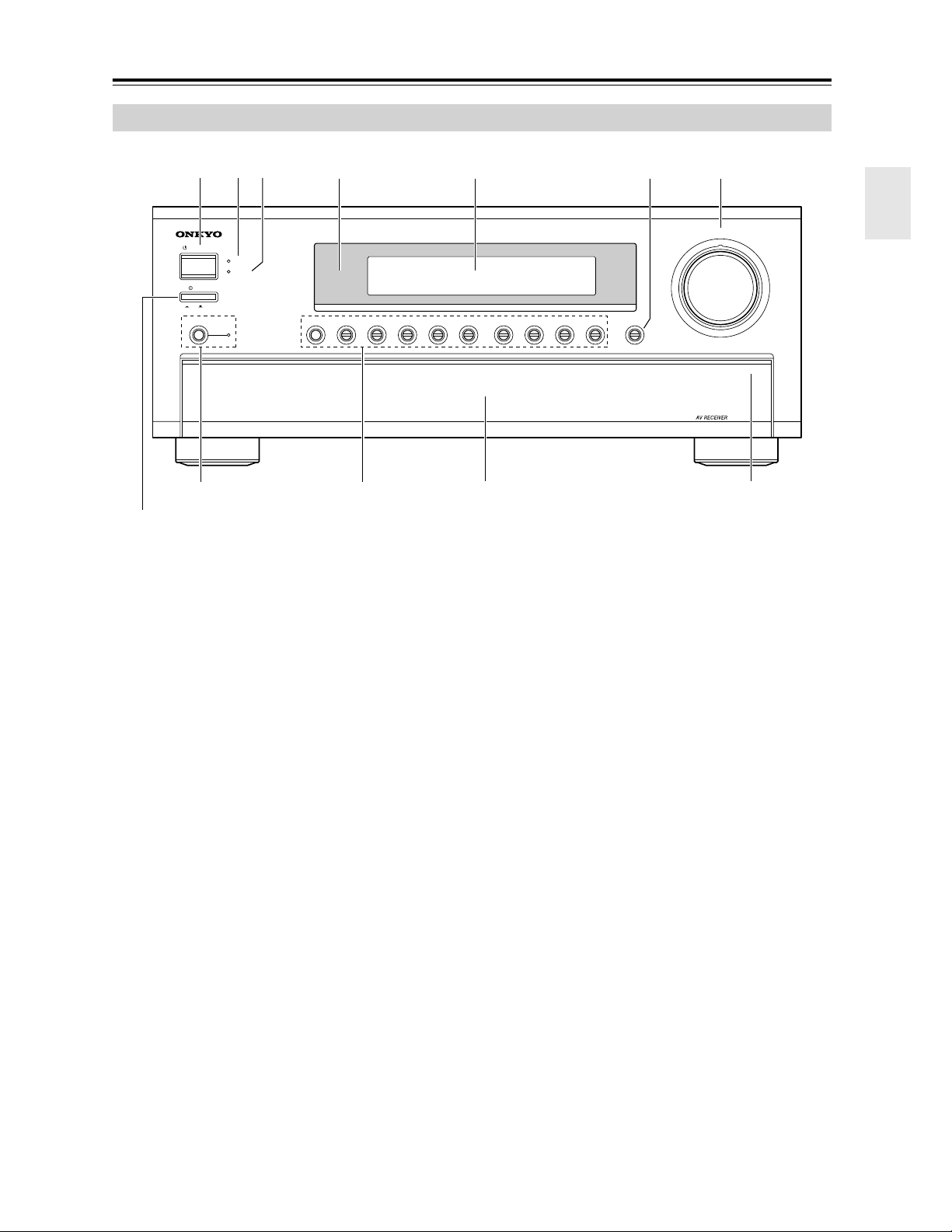
Getting to Know the AV Receiver
The actual front panel has various logos printed on it. They are not shown here for clarity.
For detailed information, see the pages in parentheses.
A STANDBY/ON button (39)
Sets the AV receiver to On or Standby.
B STANDBY indicator (39)
Lights up when the AV receiver is on Standby and
flashes while a signal is being received from the
remote controller.
C ZONE 2 indicator (83)
Lights up when Zone 2 is on.
D Remote-control sensor (13)
Receives control signals from the remote controller.
E Display
See “Display” on page 9.
F DISPLAY button (59)
Displays various information about the currently
selected input source.
G MASTER VOLUME control (48)
Sets the volume of the AV receiver to –∞ dB, –81 dB,
–80 dB through +18 dB (relative display).
The volume level can also be displayed as an abso-
lute value. See “Volume Setup” on page 78.
H Power switch
American and Australian models don’t have this
switch.
This is the main power switch. When set to OFF, the
AV receiver is completely shutdown. When set to
ON, it’s in Standby mode and the STANDBY indi-
cator lights up.
I PURE AUDIO button and indicator (60)
Selects the Pure Audio listening mode. The indica-
tor lights up when this mode is selected. Pressing
this button again selects the previous listening
mode.
J Input selector buttons (48)
Select the following input sources: MULTI CH,
DVD, VIDEO 1, VIDEO 2, VIDEO 3, VIDEO 4,
PHONO, TAPE, TUNER, or CD.
The [MULTI CH] button selects the multichannel
DVD input.
Front Panel
STANDBY/ON
STANDBY
MASTER VOLUME
PHONO
ZONE 2
DISPLAY
PURE AUDIO
TUNERTAPE
VIDEO 4VIDEO 3VIDEO 2VIDEO 1
DVDMULTI CH CD
OFF
ON
POWER
PUSH TO OPEN
4 5 76
1 2 3
J
8
9
Front flap
Not North American and Australian models
Push here to open
the flap
8
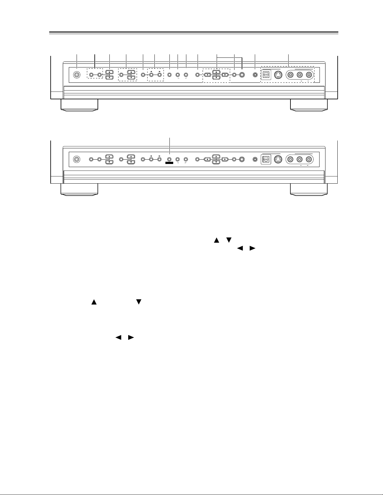
Getting to Know the AV Receiver—Continued
For detailed information, see the pages in parentheses.
K PHONES jack (59)
This 1/4-inch phone jack is for connecting a stan-
dard pair of stereo headphones for private listening.
L ZONE 2 and OFF buttons (83)
The ZONE 2 button is used to turn on Zone 2 and
select the input source for Zone 2.
The OFF button is used to turn off Zone 2.
M ZONE 2 LEVEL buttons (84)
Set the volume of the Zone 2 speakers.
N TONE, Up [ ], and Down [ ] buttons (67)
Used to adjust the bass and treble.
O STEREO button (60)
Selects the Stereo listening mode.
P LISTENING MODE [ ]/[ ] buttons (60)
Select the listening modes.
Q DIMMER (RT/PTY/TP) button (51, 58)
Adjusts the display brightness.
On the European model, this is the RT/PTY/TP but-
ton, and it’s used with RDS (Radio Data System).
See “Using RDS (European Model Only)” on
page 50.
R MEMORY button (56)
Used when storing or deleting radio presets.
S TUNING MODE button (49)
Selects the Auto or Manual tuning mode for AM
and FM radio.
T SETUP button
Opens and closes the onscreen setup menus, which
are displayed on the connected TV.
U Arrow/TUNING/PRESET and ENTER buttons
When AM, FM, or XM is selected, the TUNING
[ ] [ ] buttons are used for radio tuning, and the
PRESET [ ] [ ] buttons are used to select radio
presets (see page 56). With the onscreen setup
menus, they work as arrow buttons and are used to
select and set items. The ENTER button is also used
with the onscreen setup menus.
V RETURN button
Selects the previously displayed onscreen setup
menu.
W SETUP MIC (40)
The automatic speaker setup microphone connects
here.
X VIDEO 4 INPUT (32, 64)
Used to connect a camcorder, game console, and so
on. There are jacks for optical digital audio,
S-Video, composite video, and analog audio.
OFF TONEZONE 2
ZONE 2 LEVEL
PHONES
STEREO
RT / PTY/ TP MEMORY
LISTENING MODE
TUNING
MODE SETUP
PRESET PRESET
TUNING
RETURN
ENTER SETUP MIC
VIDEO
S VIDEO
DIGITAL
VIDEO 4 INPUT
AUDIOLR
CLEAR
RDS
Q
OFF TONEZONE 2
ZONE 2 LEVEL
PHONES
STEREO
DIMMER MEMORY
LISTENING MODE
TUNING
MODE SETUP
PRESET PRESET
TUNING
RETURN
ENTER SETUP MIC
VIDEO
S VIDEO
DIGITAL
VIDEO 4 INPUT
AUDIOLR
CLEAR
KLM N QR S T V WO P XU
On European Model

9
Getting to Know the AV Receiver—Continued
For detailed information, see the pages in parentheses.
1 MUTING indicator (58)
Flashes while the AV receiver is muted.
2 ZONE 2 indicator (83)
Lights up when Zone 2 is on.
3 Listening mode and format indicators (60)
Show the selected listening mode and the format of
digital input signals.
4 Tuning indicators (49)
TUNED (49): Lights up when tuned to a radio sta-
tion.
AUTO (49): For AM and FM radio, lights up when
Auto Tuning mode is selected, and disappears when
Manual Tuning mode is selected.
RDS (European model only) (50): Lights up
when tuned to a radio station that supports RDS
(Radio Data System).
MEMORY (56): Lights up when presetting radio
stations.
FM STEREO (49): Lights up when tuned to a ste-
reo FM station.
5 SLEEP indicator (59)
Lights up when the Sleep function has been set.
6 Message area
Displays various information about the selected
input source.
Display
2134
5
6
10
Getting to Know the AV Receiver—Continued
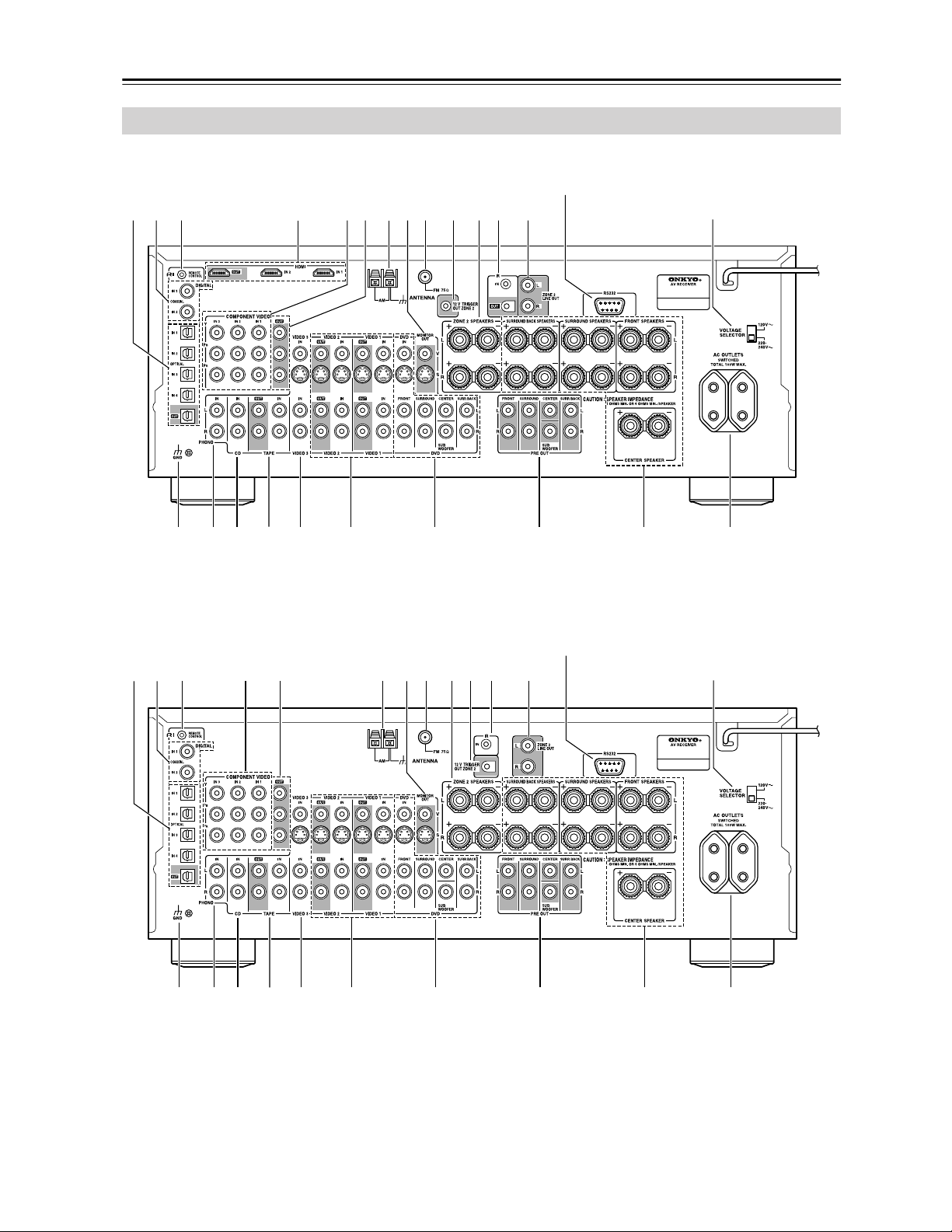
Rear Panel
P Q R S
3 4 76 85 J9 LK M
O
T U Y
21
N
VWX
TX-SR803/803E
Not North American and Australian models
On some models
P Q R S
3 76 85 J9 LK M
N
O
T U V W X Y
21
TX-SR703/703E and TX-SR8370
Not North American and Australian models
On some models
11
Getting to Know the AV Receiver—Continued
A OPTICAL DIGITAL
These optical digital audio inputs are for connecting
components with optical digital audio outputs, such
as CD players and DVD players.
The optical digital audio output is for connecting a
digital recorder with an optical digital input, such as
a CD recorder.
B COAXIAL DIGITAL
These coaxial digital audio inputs are for connect-
ing components with coaxial digital audio outputs,
such as CD players and DVD players.
C REMOTE CONTROL
This (Remote Interactive) jack can be con-
nected to the jack on another -capable
Onkyo component, for remote and system control.
To use , you must make an analog audio connec-
tion (RCA) between the AV receiver and the other
component, even if they are connected digitally.
D HDMI IN 1, 2, and OUT (TX-SR803/803E only)
HDMI (High Definition Multimedia Interface) con-
nections carry digital audio and digital video.
The HDMI inputs are for connecting components
with HDMI outputs, such as DVD players.
The HDMI output is for connecting a TV or projec-
tor with an HDMI input.
E COMPONENT VIDEO IN 1, 2, and 3
These RCA component video inputs are for con-
necting components with component video outputs,
such as DVD players.
F COMPONENT VIDEO OUT
This RCA component video output is for connect-
ing a TV or projector with a component video input.
G AM ANTENNA
These push terminals are for connecting an AM
antenna.
H MONITOR OUT
The S-Video or composite video jack should be
connected to a video input on your TV or projector.
I FM ANTENNA
This jack is for connecting an FM antenna.
J 12V TRIGGER OUT ZONE 2
This output can be connected to the 12-volt trigger
input on a component in Zone 2. When Zone 2 is
turned on on the AV receiver, a 12-volt trigger sig-
nal is output.
K ZONE 2 SPEAKERS
These terminal posts are for connecting speakers in
Zone 2.
L IR IN/OUT
A commercially available IR receiver can be con-
nected to the IR IN jack, allowing you to control the
AV receiver while you’re in Zone 2, or control it
when it’s out of sight, for example, installed in a
cabinet.
A commercially available IR emitter can be con-
nected to the IR OUT jack to pass IR (infrared)
remote control signals along to other components
(only the TX-SR803/803E has an IR OUT).
M ZONE 2 LINE OUT
This analog audio output can be connected to a line
input on an amplifier in Zone 2.
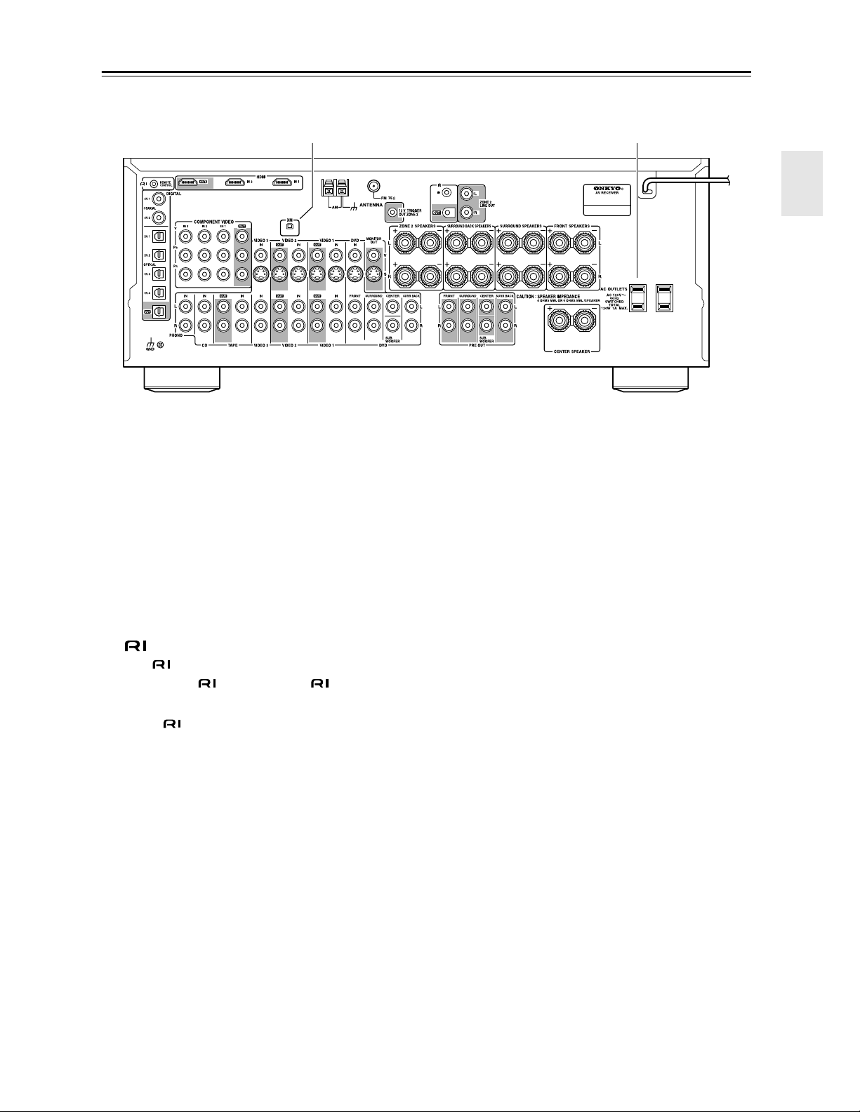
Z
Y
On North American Model
12
Getting to Know the AV Receiver—Continued
N RS232
American and Australian models don’t have this
port.
This port is for connecting the AV receiver to home
automation equipment and external controllers.
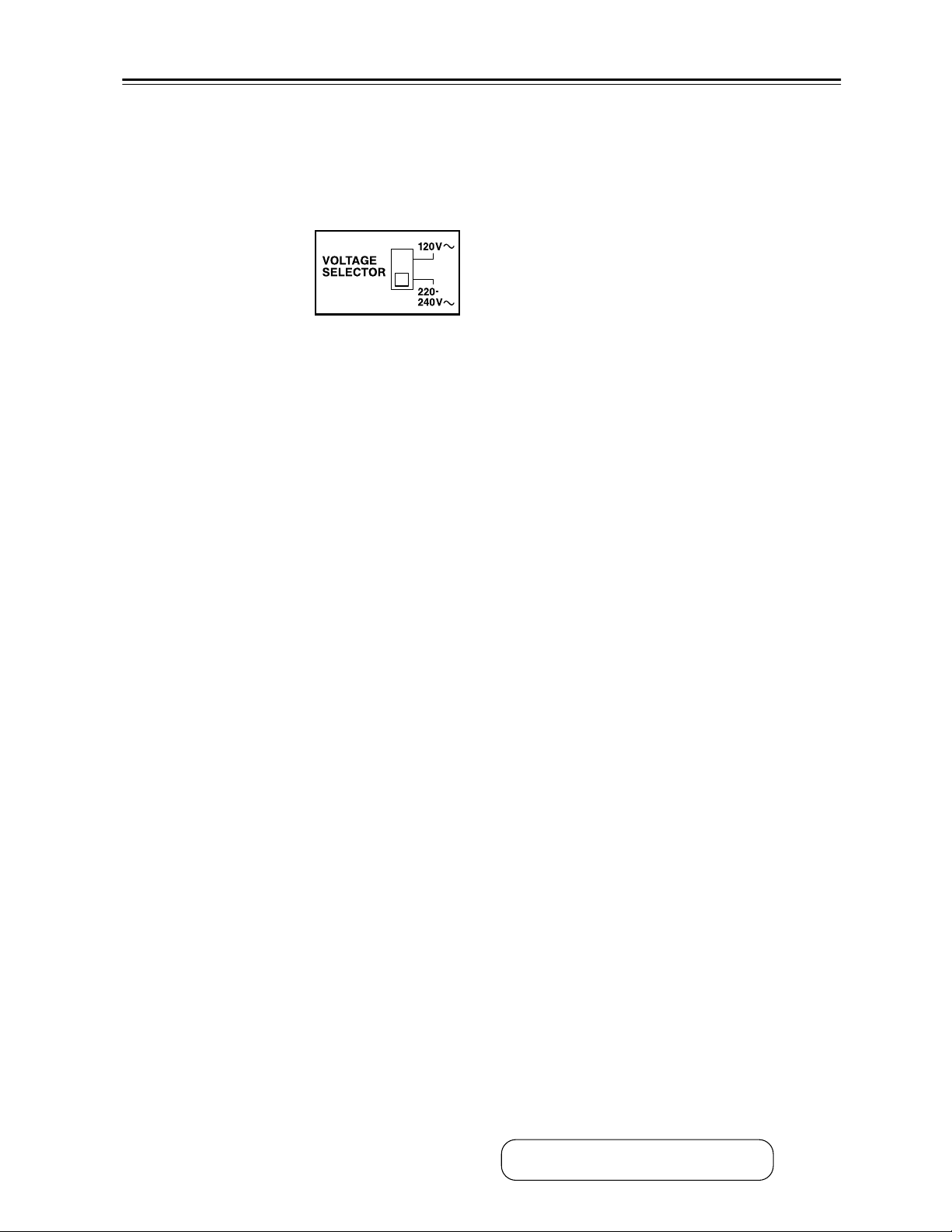
O VOLTAGE SELECTOR (on some models)
Some models have a volt-
age selector switch for
compatibility with power
systems around the world.
Before you plug in such a
model, make sure that the
voltage selector is set to the correct voltage for your
area. If it isn’t, use a small screwdriver to select the
correct setting. For example, if the voltage in your
area is 120 volts, set the selector to “120 V.” If it’s
between 220 and 240 volts, set it to “220-240 V.”
P GND screw
This screw is for connecting a turntable’s ground
wire.
Q PHONO IN
This analog audio input is for connecting a turnta-
ble.
R CD IN
This analog audio input is for connecting a CD
player’s analog audio output.
S TAPE IN/OUT
This analog audio input and output are for connect-
ing a recorder with an analog audio input and out-
put, such as a cassette deck, MD recorder, etc.
T VIDEO 3 IN
A VCR for playback only, or a cable or satellite
receiver can be connected here. There’s S-Video and
composite video input jacks for connecting the
video signal.
U VIDEO 1 IN/OUT and VIDEO 2 IN/OUT
One or two video components can be connected
here for recording and playback, such as a VCR.
There’s S-Video and composite video input and out-
put jacks for connecting the video signal.
V DVD IN
This input are for connecting a DVD player. There’s
S-Video and composite video input jacks for con-
necting the video signal, and stereo (FRONT) and
multichannel 5.1/7.1 jacks for connecting the ana-
log audio signals.
W PRE OUT FRONT L/R, SURROUND L/R,
CENTER, SUBWOOFER, and SURR BACK
L/R
This 5.1/7.1 analog audio output can be connected
to the analog audio input on another power ampli-
fier, for when you want to use the AV receiver as a
preamplifier. The SUBWOOFER jack is for con-
necting a powered subwoofer.
X FRONT, CENTER, SURROUND, and
SURROUND BACK SPEAKERS
These terminal posts are for connecting the front
L/R, center, surround L/R, and surround back L/R
speakers.
Y AC OUTLETS
These switched AC outlets can be used to supply
power to other AV components. The type and num-
ber of outlets depends on the country in which you
purchased your AV receiver.
Z XM antenna (on North American model)
This jack is for connecting an XM digital antenna,
sold separately.
See pages 19–38 for hookup information.
13
Remote Controller
Notes:
• If the remote controller doesn’t work reliably, try
replacing the batteries.
• Don’t mix new and old batteries or different types of
batteries.
• If you intend not to use the remote controller for a long
time, remove the batteries to prevent damage from
leakage or corrosion.
• Expired batteries should be removed as soon as possi-
ble to prevent damage from leakage or corrosion.
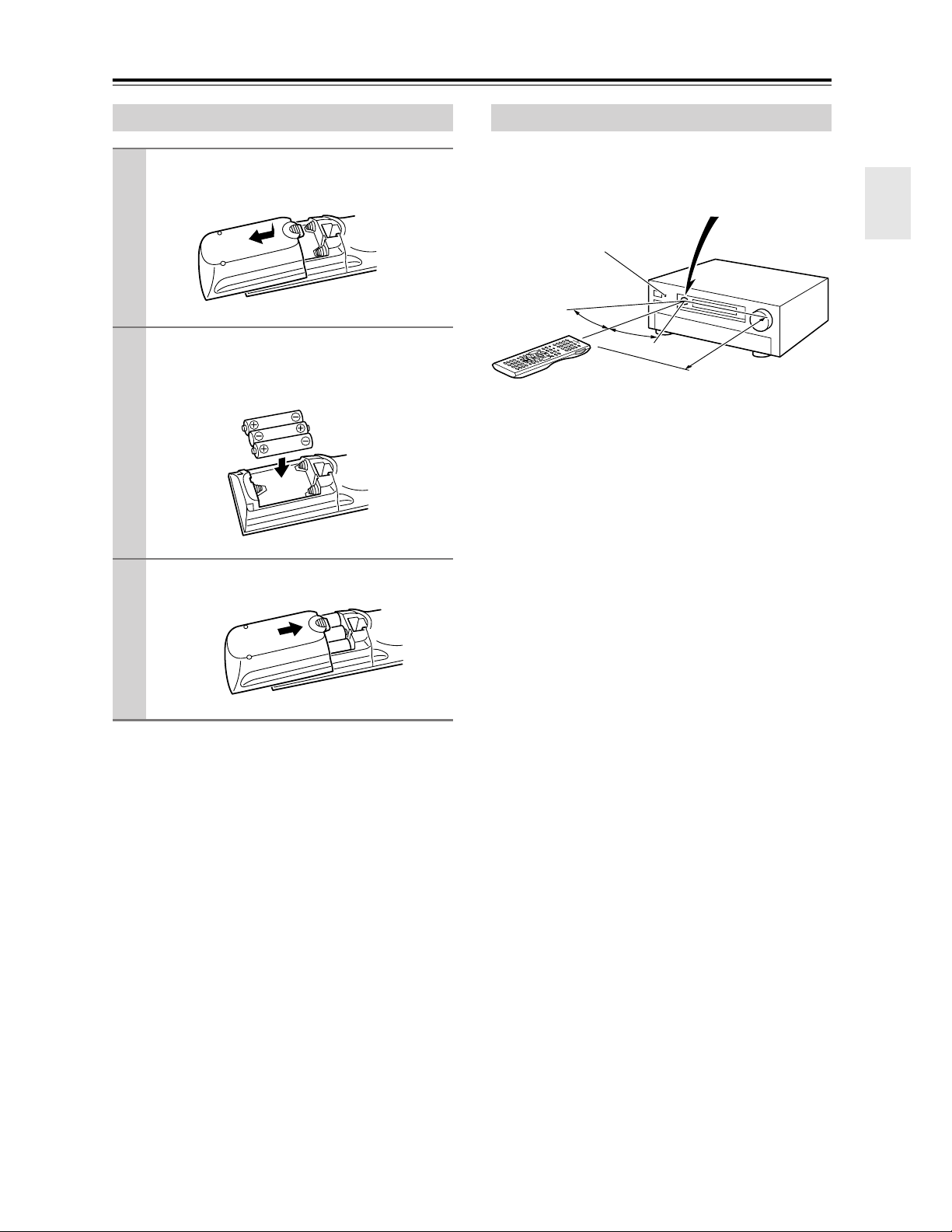
To use the remote controller, point it at the AV receiver’s
remote control sensor, as shown below.
Notes:
• The remote controller may not work reliably if the AV
receiver is subjected to bright light, such as direct sun-
light or inverter-type fluorescent lights. Keep this in
mind when installing.
• If another remote controller of the same type is used in
the same room, or the AV receiver is installed close to
equipment that uses infrared rays, the remote control-
ler may not work reliably.
• Don’t put anything on top of the remote controller,
such as a book or magazine, because a button may be
pressed continuously, thereby draining the batteries.
• The remote controller may not work reliably if the AV
receiver is installed in a rack behind colored glass
doors. Keep this in mind when installing.
• The remote controller will not work if there’s an obsta-
cle between it and the AV receiver’s remote control
sensor.
Installing the Batteries
1
To open the battery compartment, press
the small hollow and slide open the cover.
2
Insert the three supplied batteries (AA/R6)
in accordance with the polarity diagram
inside the battery compartment.
3
Slide the cover shut.
Using the Remote Controller
30˚
30˚
Approx. 16 ft.
(5 m)
Remote control sensor
STANDBY indicator
AV receiver
14
Remote Controller—Continued
Including the AV receiver, the remote controller can be
used to control up to nine different components. The
remote controller has a specific operating mode for use
with each type of component. Modes are selected by
using the eight REMOTE MODE buttons.
■ RECEIVER/TAPE Mode
In RECEIVER/TAPE mode, you can control the AV
receiver and an Onkyo cassette recorder connected via
.
■ DVD Mode
By default, you can control an Onkyo DVD player in this
mode. By entering the appropriate remote control code,
you can control components made by other manufactur-
ers (see page 86).
■ CD Mode
By default, you can control an Onkyo CD player in this
mode. By entering the appropriate remote control code,
you can control a CD player, MD recorder, or CD
recorder made by another manufacturer (see page 86).
■ HDD Mode
This mode is for controlling Onkyo’s next generation
HDD-compatible components via .
■ TV and VCR Modes
With these modes, you can control a TV and VCR. You
must enter the appropriate remote control code first (see
page 86).
■ CABLE/CDR and SAT/MD Modes
In CABLE/CDR mode, you can control an Onkyo CD
recorder or a cable TV receiver. In SAT/MD mode, you
can control an Onkyo MD recorder or a satellite TV
receiver. You must enter the appropriate remote control
code first (see page 86).
Note:
Some of the remote controller operations described in
this manual may not work as expected with other com-
ponents.
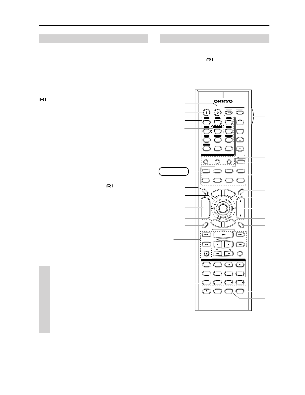
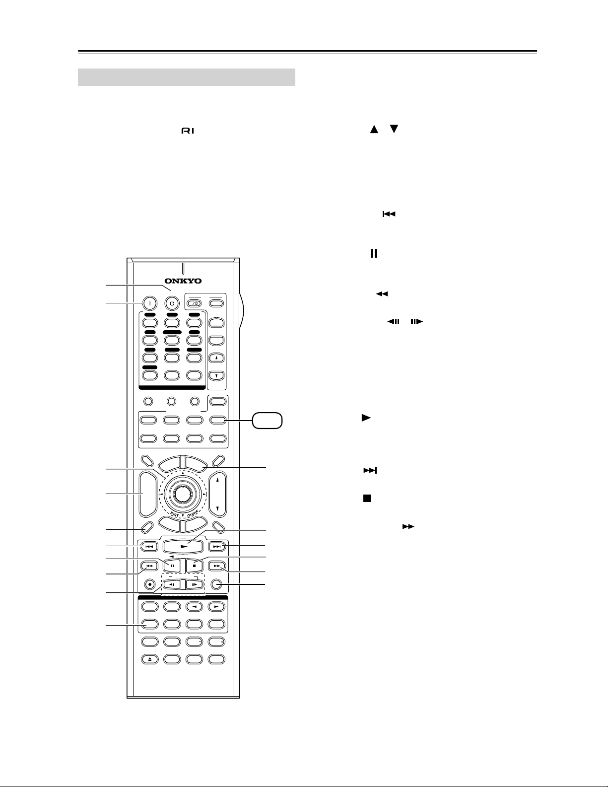
RECEIVER/TAPE mode is used to control the AV
receiver. It can also be used to control an Onkyo cassette
recorder connected via .
To set the remote controller to RECEIVER/TAPE
mode, press the [RECEIVER] REMOTE MODE
button.
About the Remote Controller Modes
1
Use the REMOTE MODE buttons to select
a mode.
2
Use the buttons supported by that mode
to control the component.
RECEIVER/TAPE mode: see page 14
DVD mode: see page 16
CD/MD/CDR modes: see page 17
HDD mode: see page 18
TV/VCR/SAT/CABLE modes: see page 88
RECEIVER/TAPE Mode
THX
10
--/---
11 12
REMOTE MODE
HDD
RECEIVER
TAPE/AMP
DVD CD
ZONE2
SAT
TV
VCR
CABLE
MDCDR
STEREO
SURR
DIRECT
SUBTITLEAUDIO
ALLST
PLAY MODE
VIDEO OFF
REPEAT
RANDOMREC PLAYLIST
OPEN/CLOSE
Re-EQ
+
-
TV CH
T
V VOL
ENTER
S
E
T
U
P
T
O
P
M
E
N
U
M
E
N
U
VOL
+
-
CH
DISPLAY
PREV
CH
DIMMER
SLEEP
MUTING
LISTENING MODE
INPUT SELECTOR
32
MACRO
1
+
10 0
CLEAR
12
3
456
789
INPUT
I
ON STANDBY
TV
CD
V1 V2 V3
MULTI CH
DVD
TUNER
PHONO
DISC
ALBUM
V4
TAPE
PURE A
TEST TONE
CH SEL LEVEL LEVEL
L NIGHT
R
E
T
U
R
N
RC-620M
1
B
K
H
O
S
F
5
I
A
Q
P
R
T
U
V
G
RECEIVER
N
L
J
M
D
C

15
Remote Controller—Continued
For detailed information, see the pages in parentheses.
A STANDBY button (39)
Sets the AV receiver to Standby.
B ON button (39)
Turns on the AV receiver.
C INPUT SELECTOR buttons (48)
Used to select the input sources.
D MULTI CH button (57)
Selects the multichannel DVD input.
E DIMMER button (58)
Adjusts the display brightness.
F Arrow [ ]/[ ]/[ ]/[ ] and ENTER buttons
Used to select and adjust settings.
G CH +/– button (56)
Selects radio presets.
H RETURN button
Returns to the previous display when changing set-
tings.
I DISPLAY button (59)
Displays various information about the currently
selected input source.
J LISTENING MODE buttons (60)
Used to select the listening modes. The [STEREO],
[SURR], and LISTENING MODE [ ]/[ ] but-
tons can be used regardless of the currently selected
remote controller mode.
K TEST TONE, CH SEL, LEVEL-, and LEVEL+
buttons (58, 73)
Used to adjust the level of each speaker.
L LIGHT button
Turns the remote controller’s illuminated buttons on
or off.
M MACRO buttons (90)
Used with the Macro function.
N ZONE 2 (84)
Used when setting the volume and input source for
Zone 2.
O REMOTE MODE buttons (14)
Used to select the remote controller modes. When a
remote controller button is pressed, the REMOTE
MODE button of the currently selected mode lights
up.
P SLEEP button (59)
Used with the Sleep function.
Q MENU button (on North American model)
(53)
Selects the search mode for XM Satellite Radio.
R VOL [ ]/[ ] button (48)
Adjusts the volume of the AV receiver regardless of
the currently selected remote controller mode.
S SETUP button
Used to change settings.
T MUTING button (58)
Mutes or unmutes the AV receiver.
U Re-EQ (66)
Turns the Re-EQ function on or off.
V L NIGHT button (68)
Turns the Late Night function on or off.
■ TAPE mode
On twin cassette decks, only Deck B can be controlled.
1 Previous and Next [ ]/[ ] buttons
The Previous [ ] button selects the previous
track. During playback it selects the beginning of
the current track. The Next [ ] button selects the
next track.
Depending on how they were recorded, the Previous
and Next [ ]/[ ] buttons may not work prop-
erly with some cassette tapes.
Play [ ] button
Starts playback.
Rewind and FF [ ]/[ ] buttons
The Rewind [ ] button starts rewind. The FF
[ ] button starts fast forward.
Reverse Play [ ] button
Starts reverse playback.
Stop [ ] button
Stops playback.
REC [ ] button
Starts recording.
16
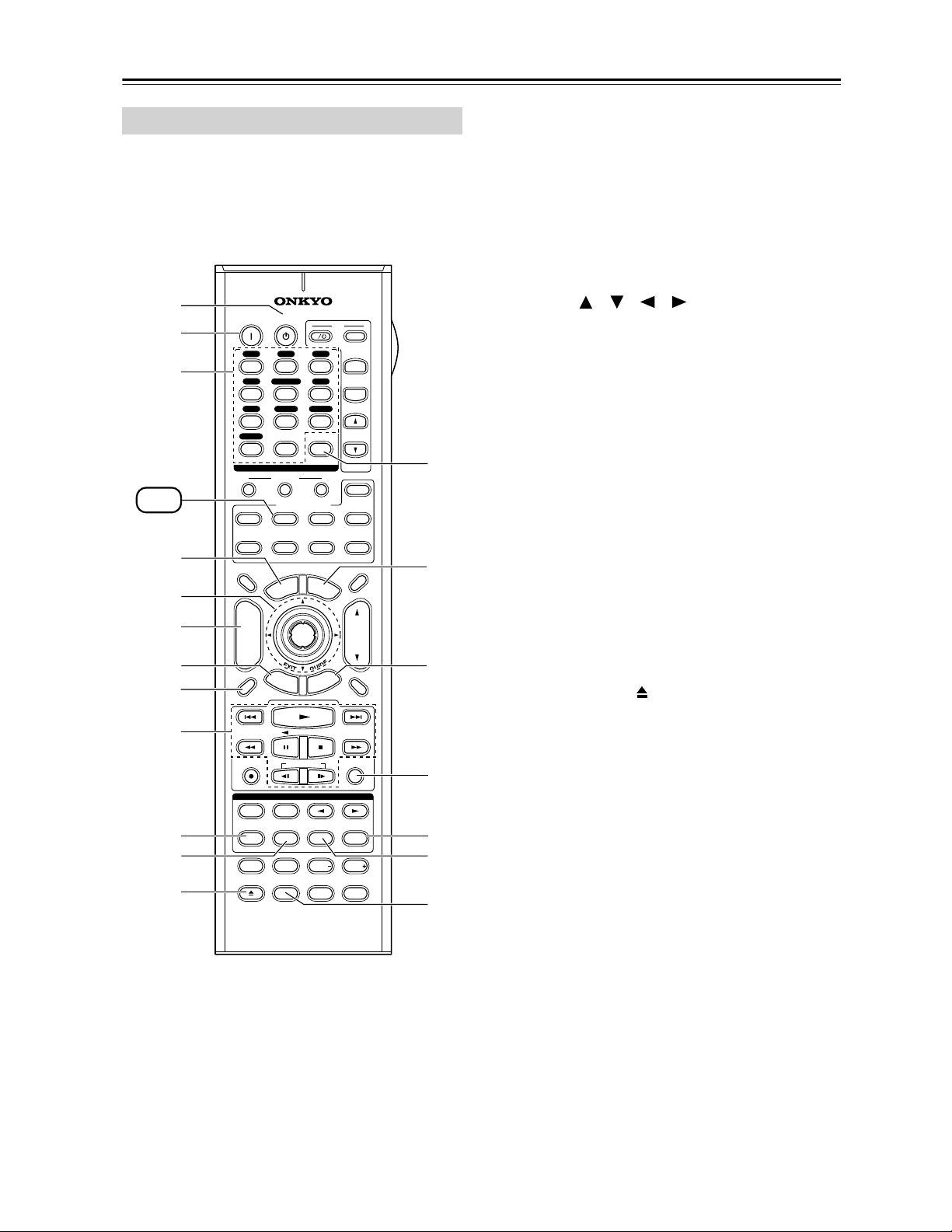
Remote Controller—Continued
To set the remote controller to DVD mode, press the
[DVD] REMOTE MODE button.
A STANDBY button
Sets the DVD player to Standby.
B ON button
Turns on the DVD player.
C Number buttons
Used to enter title, chapter, and track numbers, and
to enter times for locating specific points.
D TOP MENU button
Selects a DVD’s top menu.
E Arrow [ ]/[ ]/[ ]/[ ] and ENTER buttons
Used to navigate menus and select items.
F DISC +/– button
Selects discs on a DVD changer.
G RETURN button
Exits the DVD player’s onscreen setup menu.
H DISPLAY button
Displays information about the current disc, title,
chapter, or track, including elapsed time, remaining
time, total time, and so on.
I Playback buttons
From left to right: Previous, Play, Next, Rewind,
Pause, Stop, Fast Forward, Slow Reverse, and Slow
Forward.
J REPEAT button
Used with the repeat playback function.
K AUDIO button
Selects foreign language soundtracks and audio for-
mats (e.g., Dolby Digital or DTS).
L OPEN/CLOSE [ ] button
Opens and closes the disc tray.
M CLEAR button
Cancels functions and clears entered numbers.
N MENU button
Displays a DVD’s menu.
O SETUP button
Used to access the DVD player’s settings.
P RANDOM button
Used with the random playback function.
Q PLAY MODE button
Selects play modes on components with selectable
play modes.
R SUBTITLE button
Selects subtitles.
S VIDEO OFF button
Turns off the internal video circuitry, eliminating
any possibility of interference.
DVD Mode
THX
10
--/---
11 12
REMOTE MODE
HDD
RECEIVER
TAPE/AMP
DVD CD
ZONE2
SAT
TV
VCR
CABLE
MDCDR
STEREO
SURR
DIRECT
SUBTITLEAUDIO
ALLST
PLAY MODE
VIDEO OFF
REPEAT
RANDOMREC PLAYLIST
OPEN/CLOSE
Re-EQ
+
-
TV CH
TV VOL
ENTER
S
E
T
U
P
T
O
P
M
E
N
U
M
E
N
U
VOL
+
-
CH
DISPLAY
PREV
CH
DIMMER
SLEEP
MUTING
LISTENING MODE
INPUT SELECTOR
32
MACRO
1
+
10 0
CLEAR
12
3
456
789
INPUT
I
ON STANDBY
TV
CD
V1 V2 V3
MULTI CH
DVD
TUNER
PHONO
DISC
ALBUM
V4
TAPE
PURE A
TEST TONE
CH SEL LEVEL LEVEL
L NIGHT
R
E
T
U
R
N
RC-620M
L
B
G
H
M
Q
R
S
F
E
I
C
D
A
DVD
O
N
P
J
K
17
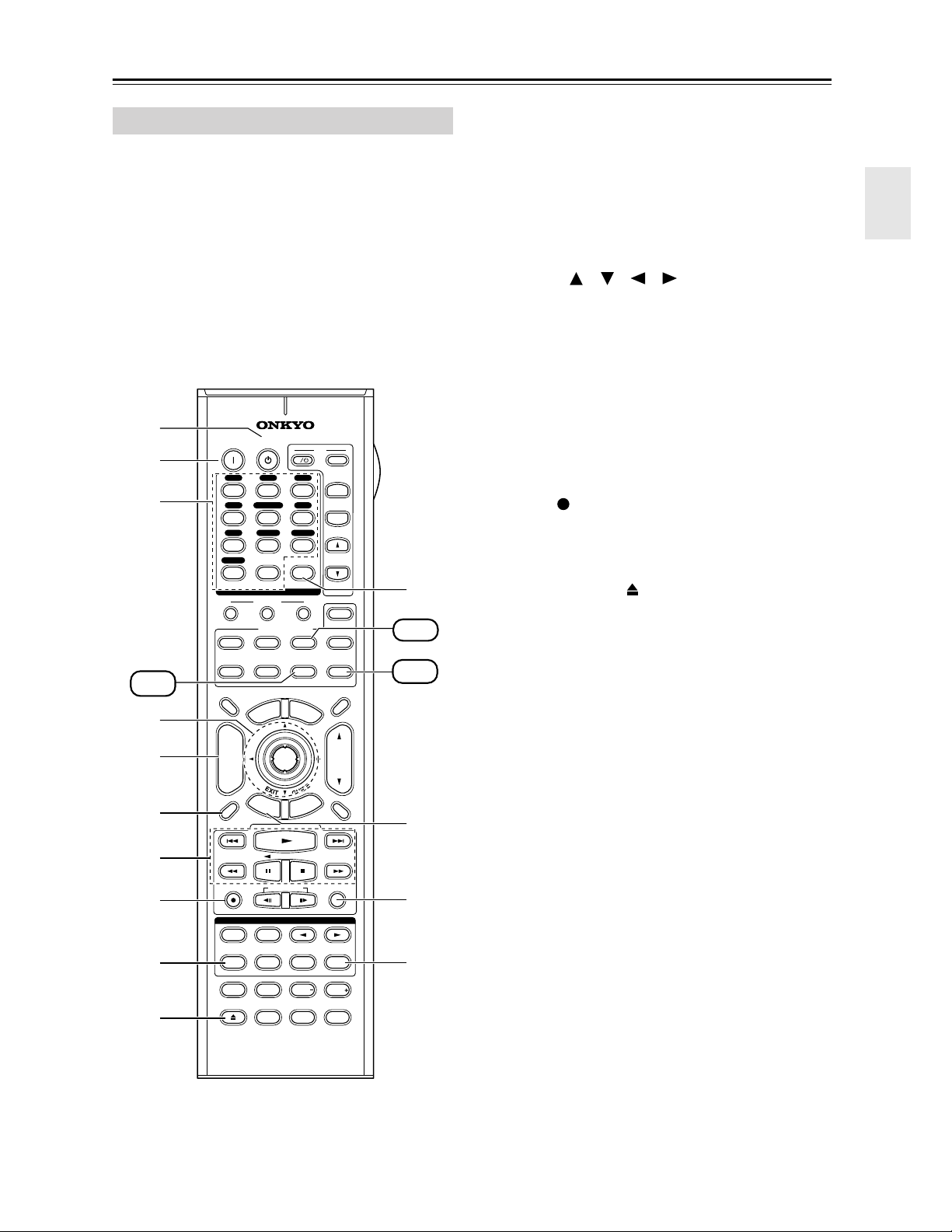
Remote Controller—Continued
To control an Onkyo CD player or a CD/MD recorder
made by another manufacturer, press the [CD]
REMOTE MODE button to select the CD remote
controller mode.
To control an Onkyo MD recorder or CD recorder,
press the [MD] or [CDR] REMOTE MODE button to
select the MD or CDR remote controller mode.
In order to control an Onkyo MD recorder or CD
recorder, or a component made by another manufacturer,
you must first enter the appropriate remote control code
(see page 86).
A STANDBY button
Sets the CD player or MD/CD recorder to Standby.
B ON button
Set the CD player or MD/CD recorder to On or
Standby.
C Number buttons
Used to enter track numbers and times for locating
specific points.
D Arrow [ ]/[ ]/[ ]/[ ] and ENTER buttons
Used with some components.
E DISC +/– button
Selects discs on a CD changer.
F DISPLAY button
Displays information about the current disc or track,
including elapsed time, remaining time, total time,
and so on.
G Playback buttons
From left to right: Previous, Play, Next, Rewind,
Pause, Stop, and Fast Forward.
H REC [ ] button
Starts recording.
I REPEAT button
Used with the repeat playback function.
J OPEN/CLOSE [ ] button
Opens and closes the disc tray or ejects the Mini-
Disc.
K CLEAR button
Cancels functions and clears entered numbers.
L RETURN button
Used with some components.
M RANDOM button
Used with the random playback function.
N PLAY MODE button
Selects play modes on components with selectable
play modes.
CD, MD, and CDR Modes
THX
10
--/---
11 12
REMOTE MODE
HDD
RECEIVER
TAPE/AMP
DVD CD
ZONE2
SAT
TV
VCR
CABLE
MDCDR
STEREO
SURR
DIRECT
SUBTITLEAUDIO
ALLST
PLAY MODE
VIDEO OFF
REPEAT
RANDOMREC PLAYLIST
OPEN/CLOSE
Re-EQ
+
-
TV CH
TV VOL
ENTER
S
E
T
U
P
T
O
P
M
E
N
U
M
E
N
U
VOL
+
-
CH
DISPLAY
PREV
CH
DIMMER
SLEEP
MUTING
LISTENING MODE
INPUT SELECTOR
32
MACRO
1
+
10 0
CLEAR
12
3
456
789
INPUT
I
ON STANDBY
TV
CD
V1 V2 V3
MULTI CH
DVD
TUNER
PHONO
DISC
ALBUM
V4
TAPE
PURE A
TEST TONE
CH SEL LEVEL LEVEL
L NIGHT
R
E
T
U
R
N
RC-620M
B
K
F
7
8
9
J
E
L
C
D
A
MD
CDR
CD
M
N
18
Remote Controller—Continued
HDD mode is for controlling Onkyo’s next generation
HDD-compatible components. As of 2005, it can be used
with the Onkyo DS-A1 Remote Interactive Dock and
Apple iPod connected via .
When Using the DS-A1:
• Connect the DS-A1 to the TAPE IN or VIDEO 3 IN
jacks.
• Set the DS-A1’s RI MODE switch to HDD.
• Set the AV receiver’s input display to HDD (see
page 46).
• Refer to the DS-A1’s instruction manual.
A STANDBY button
Turns off the HDD-compatible component.
B ON button*
Turns on the HDD-compatible component.
C Arrow [ ]/[ ] and ENTER buttons*
Used to navigate menus and select items.
D ALBUM +/– button*
Selects the next or previous album.
E DISPLAY button*
Turns on the backlight for 30 seconds.
F Previous [ ] button
Restarts the current song. Press it twice to select the
previous song.
G Pause [ ] button
Pauses playback. (With 3rd generation iPods, it
works as a Play/Pause button.)
H Rewind [ ] button
Press and hold to rewind.
I PLAYLIST [ ]/[ ] buttons*
Used to select the previous or next playlist on the
HDD-compatible component.
J REPEAT button*
Used with the repeat function.
K MENU button*
Used to access menus.
L Play [ ] button
Starts playback. If the component is off, it will turn
on automatically. (With 3rd generation iPods, this
button works as a Play/Pause button.)
M Next [ ] button
Selects the next song.
N Stop [ ] button
Stops playback and displays a menu.
O Fast Forward [ ] button
Press and hold to fast forward.
P RANDOM button*
Used with the shuffle function.
* Buttons marked with an asterisk (*) are not supported by
3rd generation iPods.
HDD Mode
THX
10
--/---
11 12
REMOTE MODE
HDD
RECEIVER
TAPE/AMP
DVD CD
ZONE2
SAT
TV
VCR
CABLE
MDCDR
STEREO
SURR
DIRECT
SUBTITLEAUDIO
ALLST
PLAY MODE
VIDEO OFF
REPEAT
RANDOMREC PLAYLIST
OPEN/CLOSE
Re-EQ
+
-
TV CH
TV VOL
ENTER
S
E
T
U
P
T
O
P
M
E
N
U
M
E
N
U
VOL
+
-
CH
DISPLAY
PREV
CH
DIMMER
SLEEP
MUTING
LISTENING MODE
INPUT SELECTOR
32
MACRO
1
+
10 0
CLEAR
12
3
456
789
INPUT
I
ON STANDBY
TV
CD
V1 V2 V3
MULTI CH
DVD
TUNER
PHONO
DISC
ALBUM
V4
TAPE
PURE A
TEST TONE
CH SEL LEVEL LEVEL
L NIGHT
R
E
T
U
R
N
RC-620M
B
M
F
5
C
D
A
O
N
P
G
8
9
J
HDD
L
K
19
Connecting Your Speakers
Thanks to the AV receiver’s superb capabilities, you can enjoy surround sound with a real sense of movement in your
own home—just like being in a movie theater or concert hall. You can enjoy DVDs featuring DTS and Dolby Digital.
With analog and digital TV, you can enjoy Dolby Pro Logic IIx and Onkyo’s own DSP surround listening modes. You
can also enjoy THX Surround EX (THX-certified THX speaker system recommended).
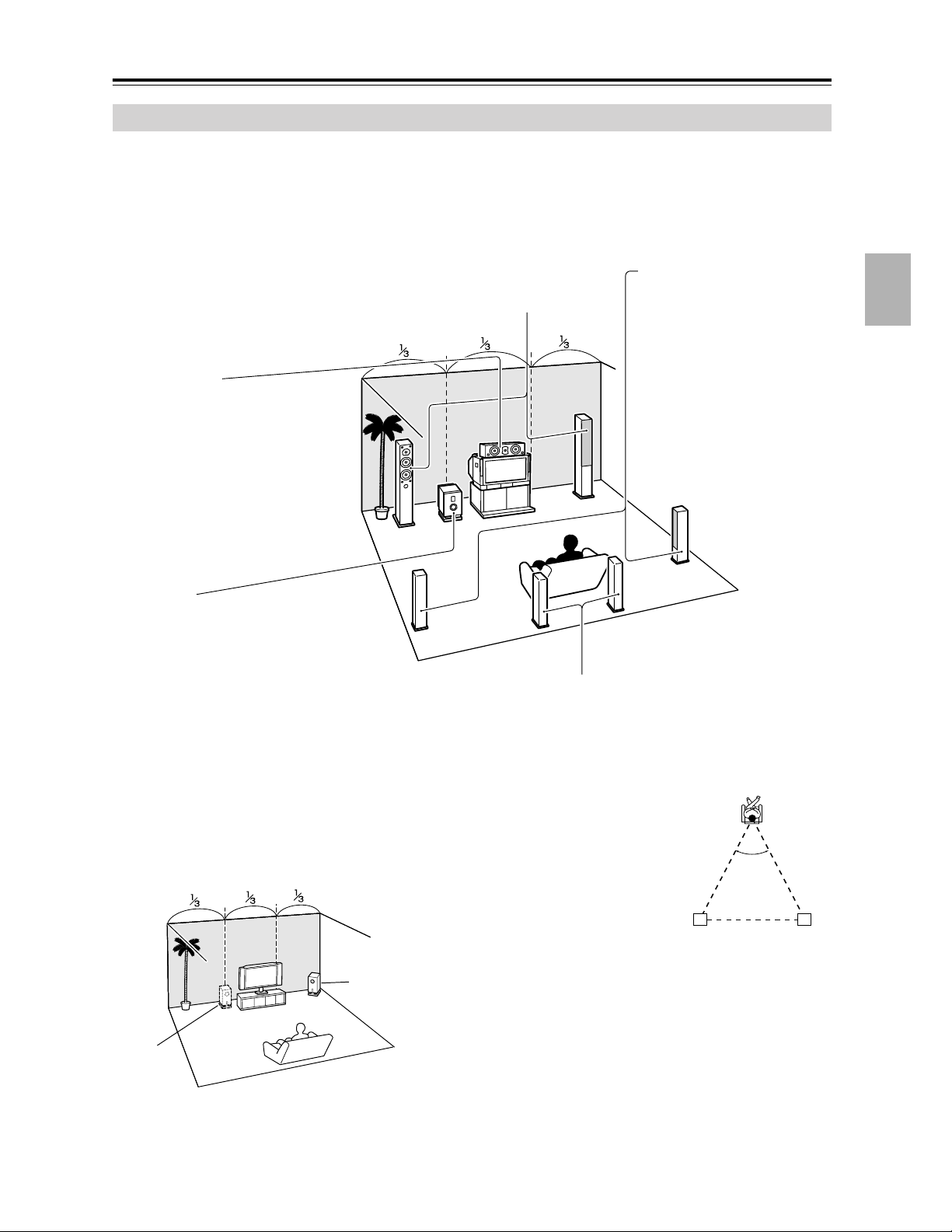
Enjoying Home Theater
Corner
position
1/3 wall
position
Front left and right speakers
These output the overall sound. Their role in a home theater is to provide a solid
anchor for the sound image. They should be positioned facing the listener at about
ear level, and equally spaced from the TV. Angle them inward slightly so as to
create a triangle, with the listener at the apex.
Center speaker
This speaker enhances the front left
and right speakers, making sound
movements distinct and providing a
full sound image. For movies it’s used
mainly for dialog.
Position it close to your TV (preferably
on top) facing forward at about ear
level, or at the same height as the
front left and right speakers.
Subwoofer
The subwoofer handles the bass sounds of
the LFE (Low-Frequency Effects) channel.
The volume and quality of the bass output
from your subwoofer will depend on its posi-
tion, the shape of your listening room, and
your listening position. In general, a good
bass sound can be obtained by installing the
subwoofer in a front corner, or at one-third
the way along the wall, as shown.
Tip: To find the best position for your sub-
woofer, while playing a movie or some
music with good bass, experiment by plac-
ing your subwoofer at various positions
within the room, and choose the one that
provides the most satisfying results.
Surround back left and right speakers
These speakers are necessary to enjoy Dolby Digital EX, DTS-ES
Matrix, DTS-ES Discrete, THX Surround EX, etc. They enhance the real-
ism of surround sound and improve sound localization behind the lis-
tener. Position them behind the listener about 2–3 feet (60–100 cm)
above ear level.
THX recommends that they be equally
spaced from the listener, creating a triangle,
and that the angle at the apex of the triangle
be about 60 degrees. Make sure that the lis-
tening position is within range of the speak-
ers.
60˚
Surround
back left
speaker
Surround
back right
speaker
Surround left and right
speakers
These speakers are used for
precise sound positioning and
to add realistic ambience.
Position them at the sides of
the listener, or slightly behind,
about 2–3 feet (60–100 cm)
above ear level. Ideally they
should be equally spaced
from the listener.
20
Connecting Your Speakers—Continued
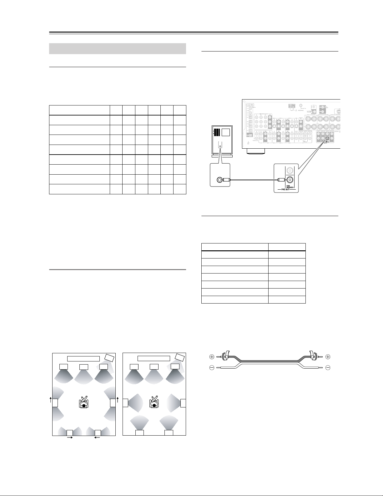
Speaker Configuration
For the best surround-sound experience, you should con-
nect seven speakers and a powered subwoofer.
The following table shows which channels you should
use based on the number of speakers you have.
*If you’re using only one surround back speaker, connect it to
the left (L) SURROUND BACK SPEAKERS terminals.
No matter how many speakers you use, a powered sub-
woofer is recommended for a really powerful and solid
bass.
To get the best from your surround-sound system, you
need to set the speaker settings by using the supplied
setup microphone (see page 40).
Using Dipole Speakers
You can use dipole speakers for the surround left and
right and surround back left and right speakers. Dipole
speakers output the same sound in two directions.
Dipole speakers typically have an arrow printed on them to
indicate how they should be positioned. The surround left
and right dipole speakers should be positioned so that their
arrows point toward the TV/screen, while the surround
back left and right dipolar speakers should be positioned
so that their arrows point toward each other, as shown.
Connecting a Powered Subwoofer
Using a suitable cable, connect the AV receiver’s SUB-
WOOFER PRE OUT to the input on your powered sub-
woofer. If your subwoofer is unpowered and you’re
using an external amplifier, connect the SUBWOOFER
PRE OUT to the amp’s input.
Attaching the Speaker Labels
The AV receiver’s positive (+) speaker terminals are
color-coded for ease of identification. (The negative (–)
speaker terminals are all black.)
The supplied speaker labels are also color-coded and you
should attach them to the positive (+) side of each
speaker cable in accordance with the above table. All you
need to do then is to match the color of each label to the
corresponding speaker terminal.
Connecting Your Speakers
Number of speakers: 234567
Front left ✓✓✓✓✓✓
Front right ✓✓✓✓✓✓
Center ✓ ✓✓✓
Surround left ✓✓✓✓
Surround right ✓✓✓✓
Surround back ✓
Surround back left* ✓
Surround back right* ✓
2
1
3
4
2
1
3
4
5
7 8
6
5
6
78
TV/screen TV/screen
1. Subwoofer
2. Front left speaker
3. Center speaker
4. Front right speaker
5. Surround left speaker
6. Surround right speaker
7. Surround back left
speaker
8. Surround back right
speaker
Dipole speakers
Normal speakers
Speaker terminal Color
Front left, Zone 2 left White
Front right, Zone 2 right Red
Center Green
Surround left Blue
Surround right Gray
Surround back left Brown
Surround back right Tan
LINE INPUT
LINE INPUT
Powered
subwoofer
21
Connecting Your Speakers—Continued
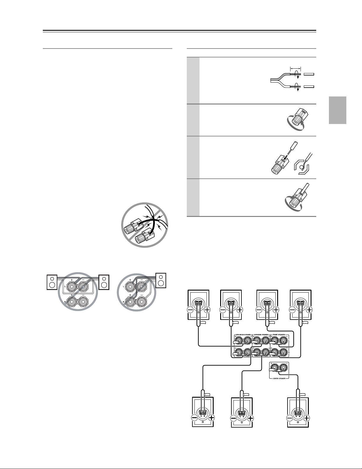
Speaker Connection Precautions
Read the following before connecting your speakers:
• You can connect speakers with an impedance of
between 4 and 16 ohms. If the impedance of any of the
connected speakers is 4 ohms or more but less than 6,
be sure to set the minimum speaker impedance to 4
ohms (see page 46). If you use speakers with a lower
impedance, and use the amplifier at high volume lev-
els for a long period of time, the built-in amp protec-
tion circuit may be activated.
• Disconnect the power cord from the wall outlet before
making any connections.
• Read the instructions supplied with your speakers.
• Pay close attention to speaker wiring polarity. In other
words, connect positive (+) terminals to only positive
(+) terminals, and negative (–) terminals to only nega-
tive (–) terminals. If you get them the wrong way
around, the sound will be out of phase and will sound
unnatural.
• Unnecessarily long or very thin speaker cables may
affect the sound quality and should be avoided.
• Be careful not to short the
positive and negative wires.
Doing so may damage the AV
receiver.
• Don’t connect more than one
cable to each speaker termi-
nal. Doing so may damage the
AV receiver.
• Don’t connect a speaker to several terminals.
Connecting the Speaker Cables
The following illustration shows which speaker should
be connected to each pair of terminals.
If you’re using only one surround back speaker, connect
it to the left (L) SURROUND BACK SPEAKERS termi-
nals.
1
Strip about 5/8" (15
mm) of insulation from
the ends of the
speaker cables, and
twist the bare wires
tightly, as shown.
2
Unscrew the terminal.
3
Fully insert the bare
wires.
4
Screw the terminal tight.
5/8" (15 mm)
Surround
back left
speaker
Surround
back right
speaker
Front left
speaker
Front right
speaker
Center
speaker
Surround
right speaker
Surround left
speaker
22
Connecting Antenna
This section explains how to connect the supplied indoor
FM antenna and AM loop antenna, and how to connect
commercially available outdoor FM and AM antennas.
The AV receiver won’t pick up any radio signals without
any antenna connected, so you must connect the antenna
to use the tuner.
The supplied indoor FM antenna is for indoor use only.
If you cannot achieve good reception with the supplied
indoor FM antenna, try a commercially available out-
door FM antenna instead (see page 23).
The supplied indoor AM loop antenna is for indoor use
only.
If you cannot achieve good reception with the supplied
indoor AM loop antenna, try using it with a commer-
cially available outdoor AM antenna (see page 23).
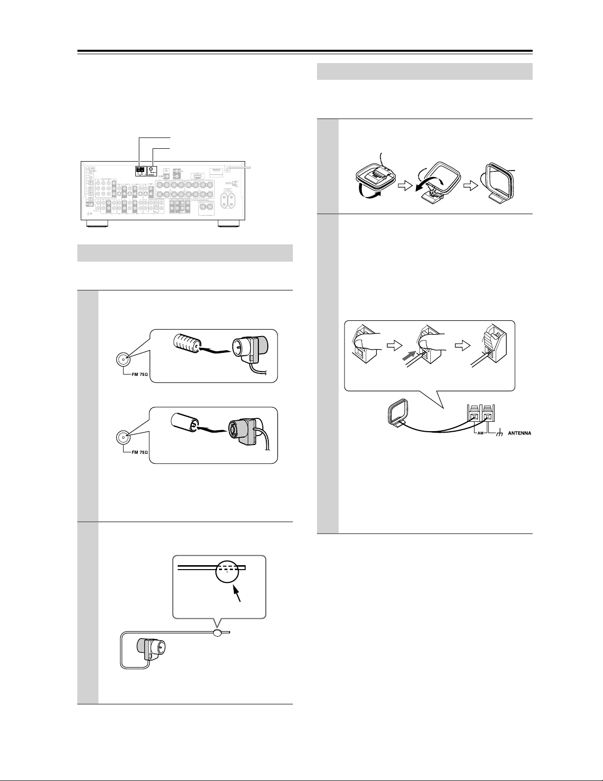
Connecting the Indoor FM Antenna
1
Attach the FM antenna, as shown.
■ American Model
■ Other Models
Once your AV receiver is ready for use, you’ll
need to tune into an FM radio station and adjust
the position of the FM antenna to achieve the best
possible reception.
2
Use thumbtacks or something similar to
fix the FM antenna into position.
Caution: Be careful that you don’t injure yourself
when using thumbtacks.
AM antenna push terminals
FM antenna jack
Insert the plug fully
into the jack.
Insert the plug fully
into the jack.
Thumbtacks, etc.
Connecting the AM Loop Antenna
1
Assemble the AM loop antenna, inserting
the tabs into the base, as shown.
2
Connect both wires of the AM loop
antenna to the AM push terminals, as
shown.
(The antenna’s wires are not polarity sensitive, so
they can be connected either way around).
Make sure that the wires are attached securely and
that the push terminals are gripping the bare
wires, not the insulation.
Once your AV receiver is ready for use, you’ll
need to tune into an AM radio station and adjust
the position of the AM antenna to achieve the best
possible reception.
Keep the antenna as far away as possible from
your AV receiver, TV, speaker cables, and power
cords.
Push Insert wire Release
23
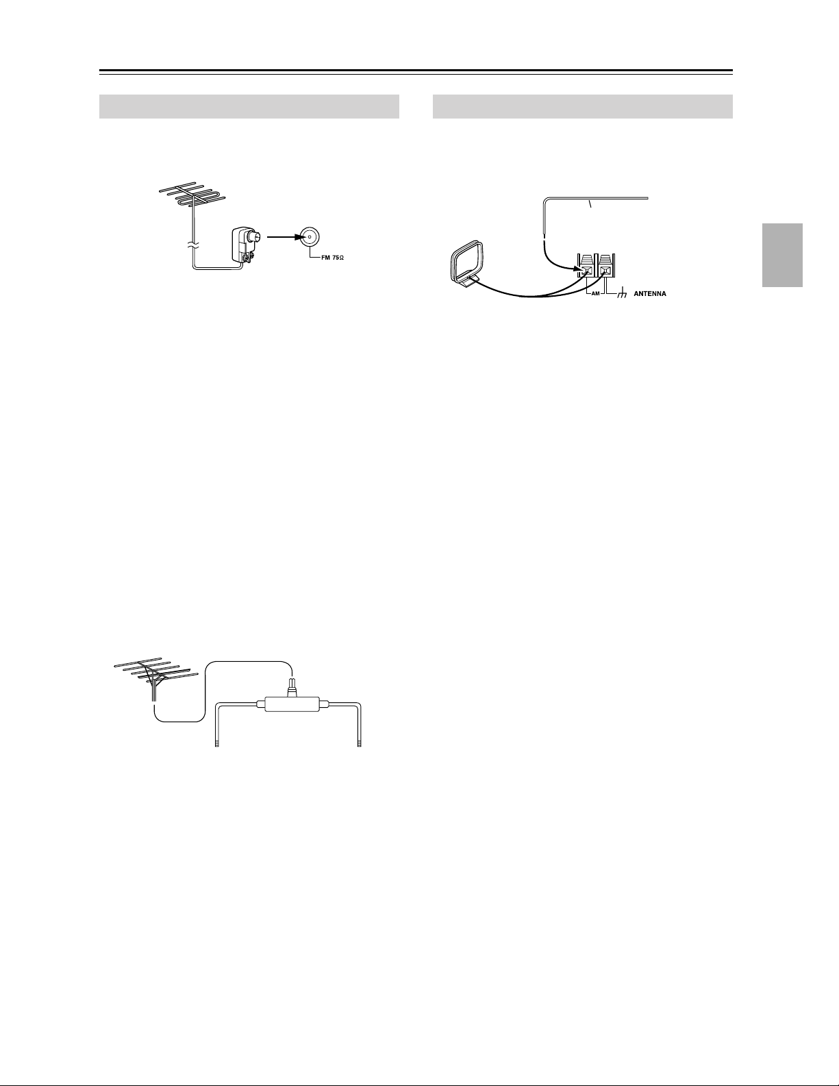
Connecting Antenna—Continued
If you cannot achieve good reception with the supplied
indoor FM antenna, try a commercially available out-
door FM antenna instead.
Notes:
• Outdoor FM antennas work best outside, but usable
results can sometimes be obtained when installed in an
attic or loft.
• For best results, install the outdoor FM antenna well
away from tall buildings, preferably with a clear line
of sight to your local FM transmitter.
• Outdoor antenna should be located away from possi-
ble noise sources, such as neon signs, busy roads, etc.
• For safety reasons, outdoor antenna should be situated
well away from power lines and other high-voltage
equipment.
• Outdoor antenna must be grounded in accordance
with local regulations to prevent electrical shock haz-
ards.
■ Using a TV/FM Antenna Splitter
It’s best not to use the same antenna for both FM and TV
reception, as this can cause interference problems. If cir-
cumstances demand it, use a TV/FM antenna splitter, as
shown.
If good reception cannot be achieved using the supplied
AM loop antenna, an outdoor AM antenna can be used in
addition to the loop antenna, as shown.
Outdoor AM antennas work best when installed horizon-
tally outside, but good results can sometimes be obtained
indoors by mounting horizontally above a window. Note
that the AM loop antenna should be left connected.
Outdoor antenna must be grounded in accordance with
local regulations to prevent electrical shock hazards.
Connecting an Outdoor FM Antenna
To AV receiver To TV (or VCR)
TV/FM antenna splitter
Connecting an Outdoor AM Antenna
Outdoor antenna
AM loop antenna
Insulated antenna cable

24
Connecting Your Components
• Before making any AV connections, read the manuals
supplied with your other AV components.
• Don’t connect the power cord until you’ve completed
and double-checked all AV connections.
Optical Digital Jacks
The AV receiver’s optical digital jacks have shutter-type
covers that open when an optical plug is inserted and
close when it’s removed. Push plugs in all the way.
Caution: To prevent shutter damage, hold the optical
plug straight when inserting and removing.
AV Connection Color Coding
RCA-type AV connections are usually color coded: red,
white, and yellow. Use red plugs to connect right-chan-
nel audio inputs and outputs (typically labeled “R”). Use
white plugs to connect left-channel audio inputs and out-
puts (typically labeled “L”). And use yellow plugs to
connect composite video inputs and outputs.
• Push plugs in all the way to make
good connections (loose connec-
tions can cause noise or malfunc-
tions).
• To prevent interference, keep
audio and video cables away from
power cords and speaker cables.
AV Cables and Jacks
Note: The AV receiver does not support SCART connections.
About AV Connections
Left (white)
Right (red)
(Yellow)
Analog audio
Composite video
Left (white)
Right (red)
(Yellow)
Right!
Wrong!
Video
Cable Jack Description
Component
video cable
Component video separates the luminance (Y) and
color difference signals (P
R, PB), providing the best
picture quality. (Some TV manufacturers label their
component video jacks slightly differently.)
S-Video cable
S-Video separates the luminance and color signals
and provides better picture quality than composite
video.
Composite
video cable
Composite video is commonly used on TVs, VCRs,
and other video equipment.
Audio
Cable Jack Description
Optical digital
audio cable
This offers the best sound quality and allows you to
enjoy Dolby Digital and DTS. The audio quality is
the same as for coaxial.
Coaxial digital
audio cable
This offers the best sound quality and allows you to
enjoy Dolby Digital and DTS. The audio quality is
the same as for optical.
Analog audio
cable (RCA)
This cable carries analog audio. It’s the most com-
mon connection format for analog audio and can be
found on virtually all AV components.
Multichannel
analog audio
cable (RCA)
This cable carries multichannel analog audio and is
typically used to connect DVD players with a 7.1-
channel analog audio output. Several standard ana-
log audio cables can be used instead of a multichan-
nel cable.
Y
P
R
P
B
P
R
P
B
Y
Y
P
B
PR
S
V
OPTICAL
COAXIAL
L
R
25
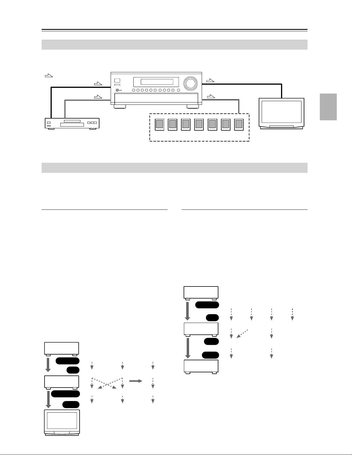
Connecting Your Components—Continued
By connecting both the audio and video outputs of your DVD player and other AV components to the AV receiver, you
can switch the audio and video signals simultaneously simply by changing the input source on the AV receiver.
The AV receiver supports several connection formats for compatibility with a wide range of AV equipment. The format
you choose will depend on the formats supported by your other components. Use the following sections as a guide.
For video components, you must make an audio connection and a video connection.
Video Connection Formats
Video equipment can be connected to the AV receiver by
using any one of the following video connection formats:
composite video, S-Video, or component video, the lat-
ter offering the best picture quality.
Composite video to S-Video and S-Video to composite
video conversion only applies to the MONITOR OUT V
and S outputs, not the VIDEO 1 and VIDEO 2 OUT V
and S outputs.
Note: The AV receiver can be set to upconvert composite
video and S-Video input signals and output them from
the COMPONENT VIDEO OUT (see page 44).
For optimum video performance, THX recommends
that video signals pass through without upconversion
(i.e., Composite video input to Composite video out-
put; S-Video input to S-Video output; Component
video input to Component video output).
Video Signal Flow Chart
Audio Connection Formats
Audio equipment can be connected to the AV receiver by
using any of the following audio connection formats:
analog, optical, coaxial, or analog multichannel.
When choosing a connection format, bear in mind that
the AV receiver does not convert digital input signals for
analog line output and vice versa. For example, audio
signals connected to an OPTICAL or COAXIAL input
are not output by the analog TAPE OUT.
Audio Signal Flow Chart
Connecting Audio and Video Signals to the AV Receiver
: Signal Flow
Video
Video
Audio
Speakers (see page 21 for hookup details)
DVD player, etc.
TV, projector,
etc.
Audio
Which Connections Should I Use?
DVD player,
etc.
AV receiver
TV,
projector,
etc.
Composite
Output
Input
Composite
Composite
Composite
S-Video
S-Video
S-Video
S-Video
Component
Component
Component
Component
page 44
IN
MONITOR OUT
DVD player,
etc.
AV receiver
MD recorder,
etc.
Optical
Output
Input
Optical
Optical
Coaxial
Coaxial
Analog
Analog
Analog
Multichannel
Multichannel
Optical
Analog
IN
OUT
26
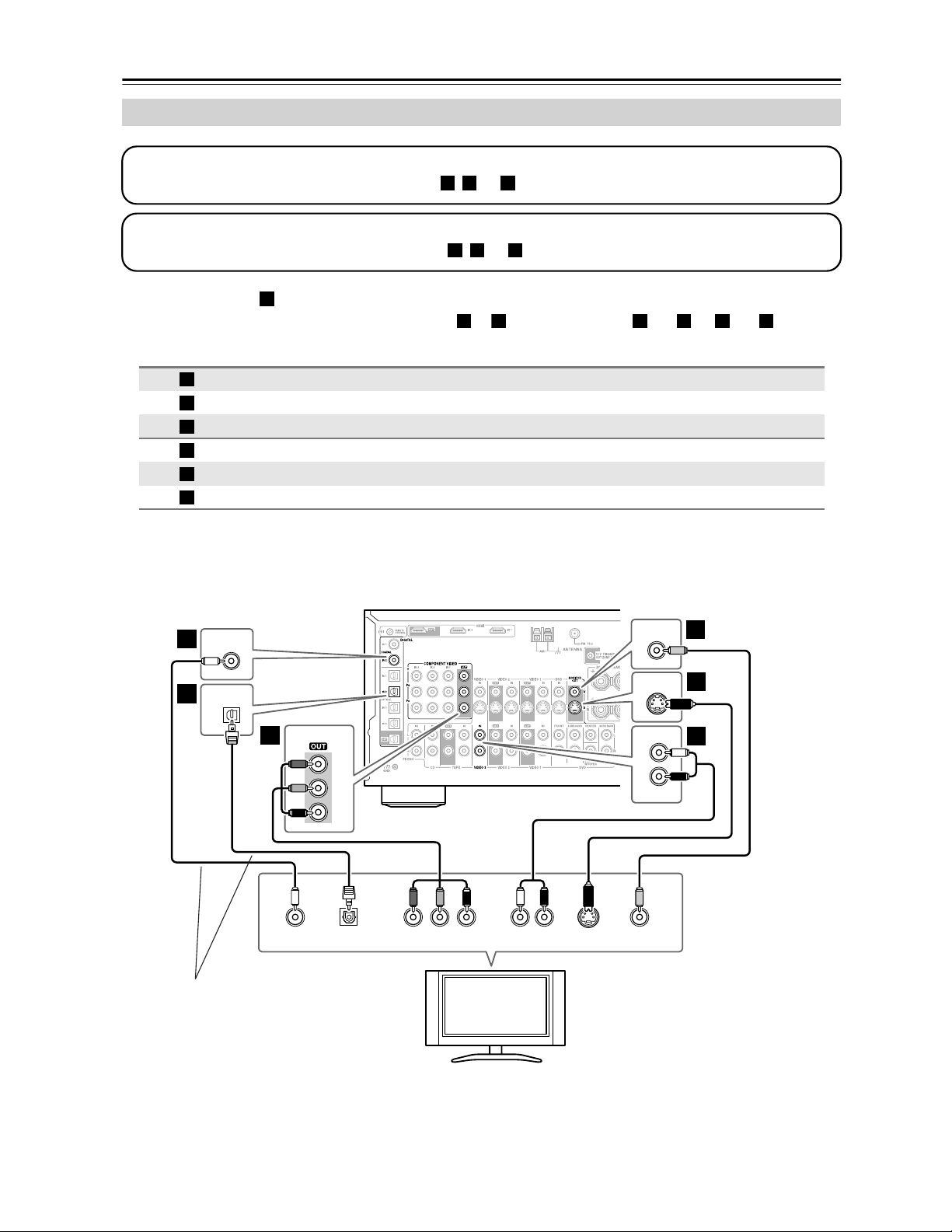
Connecting Your Components—Continued
• With connection , you can listen to and record audio from your TV and listen in Zone 2.
• To enjoy Dolby Digital and DTS, use connection or . (For recording, use and , or and .)
Hint!
If your TV has no audio outputs, connect an audio output from your VCR to the AV receiver and use its tuner to lis-
ten to TV programs through the AV receiver.
Connecting a TV or Projector
Connection AV receiver Signal flow TV Picture quality
COMPONENT VIDEO OUT
⇒
Component video input Best
MONITOR OUT S
⇒
S-Video input Better
MONITOR OUT V
⇒
Composite video input Standard
VIDEO 3 IN L/R
⇐
Analog audio L/R output
DIGITAL COAXIAL IN 2
⇐
Digital coaxial output
DIGITAL OPTICAL IN 2
⇐
Digital optical output
Step 1: Video Connection
Choose a video connection that matches your TV ( , , or ), and then make the connection.
A B C
Step 2: Audio Connection
Choose an audio connection that matches your TV ( , , or ), and then make the connection.
a b c
a
b
c
a b a c
A
B
C
a
b
c
COAXIAL
IN 2
YCOAXIAL
OUT
PB
COMPONENT VIDEO IN
P
R S VIDEO
IN
AUDIO
OUT
VIDEO
IN
MONITOR
OUT
V
S
MONITOR
OUT
LR
OPTICAL
OUT
OPTICAL
IN 2
Y
P
B
PR
COMPONENT VIDEO
L
R
IN
VIDEO 3
b
c
A
B
C
B
a
C
TV, projector,
etc.
Connect one
or the other
27
Connecting Your Components—Continued
• With connection , you can listen to and record audio from a DVD and listen in Zone 2.
• To enjoy Dolby Digital and DTS, use connection or . (For recording, use and , or and .)
• If your DVD player has main left and right outputs and multichannel left and right outputs, be sure to use the
main left and right outputs for connection .
Connecting a DVD player
Connection AV receiver Signal flow DVD player Picture quality
COMPONENT VIDEO IN 1
⇐
Component video output Best
DVD IN S
⇐
S-Video output Better
DVD IN V
⇐
Composite video output Standard
DVD IN FRONT
⇐
Analog audio L/R output
DIGITAL COAXIAL IN 1
⇐
Digital coaxial output
DIGITAL OPTICAL IN 4
⇐
Digital optical output
Step 1: Video Connection
Choose a video connection that matches your DVD player ( , , or
), and then make the connection.
If you use connection , you must connect the AV receiver to your TV with the same type of connection.
A B C
A
Step 2: Audio Connection
Choose an audio connection that matches your DVD player ( , , or ), and then make the connection.
a
b c
a
b c a b a c
a
A
B
C
a
b
c
COAXIAL
IN 1
YCOAXIAL
OUT
PB
COMPONENT VIDEO OUT
P
R S VIDEO
OUT
AUDIO
OUT
VIDEO
OUT
DVD
IN
V
S
DVD
IN
LR
OPTICAL
OUT
OPTICAL
IN 4
Y
P
B
PR
COMPONENT VIDEO
IN 1
L
R
FRONT
IN
b
c
A
B
C
B
a
C
DVD player
To connect a DVD player or DVD-Audio/SACD-capable player with a
multichannel analog audio output, see page 28.
Connect one
or the other
28
Connecting Your Components—Continued
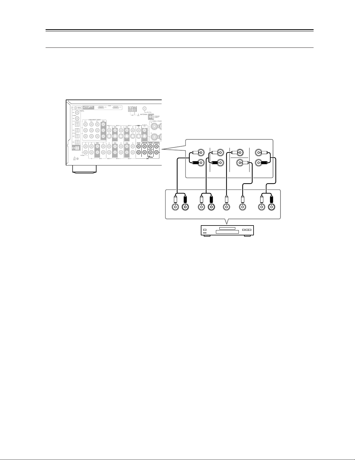
Hooking Up the Multichannel DVD Input
If your DVD player supports multichannel audio formats such as DVD-Audio or SACD, and it has a multichannel
analog audio output, you can connect it to the AV receiver’s multichannel DVD input.
Use a multichannel analog audio cable, or several normal audio cables, to connect the AV receiver’s DVD IN FRONT
L/R, CENTER, SURROUND L/R, SURR BACK L/R, and SUBWOOFER jacks to the 7.1-channel analog audio output
on your DVD player. If your DVD player has a 5.1-channel analog audio output, don’t connect anything to the AV
receiver’s SURR BACK L/R jacks. See “Using the Multichannel DVD Input” on page 57 for setup and operation.
R
FRONT
LLR
SURROUND
CENTER SUB
WOOFER
FRONT
SURROUND
DVD
SUB
WOOFER
CENTER
R
L
R
L
LR
SURR
BACK
SURR BACK
DVD player
29
Connecting Your Components—Continued
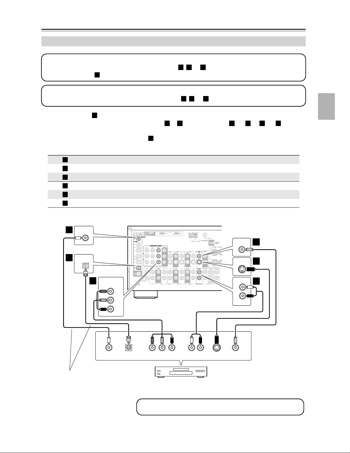
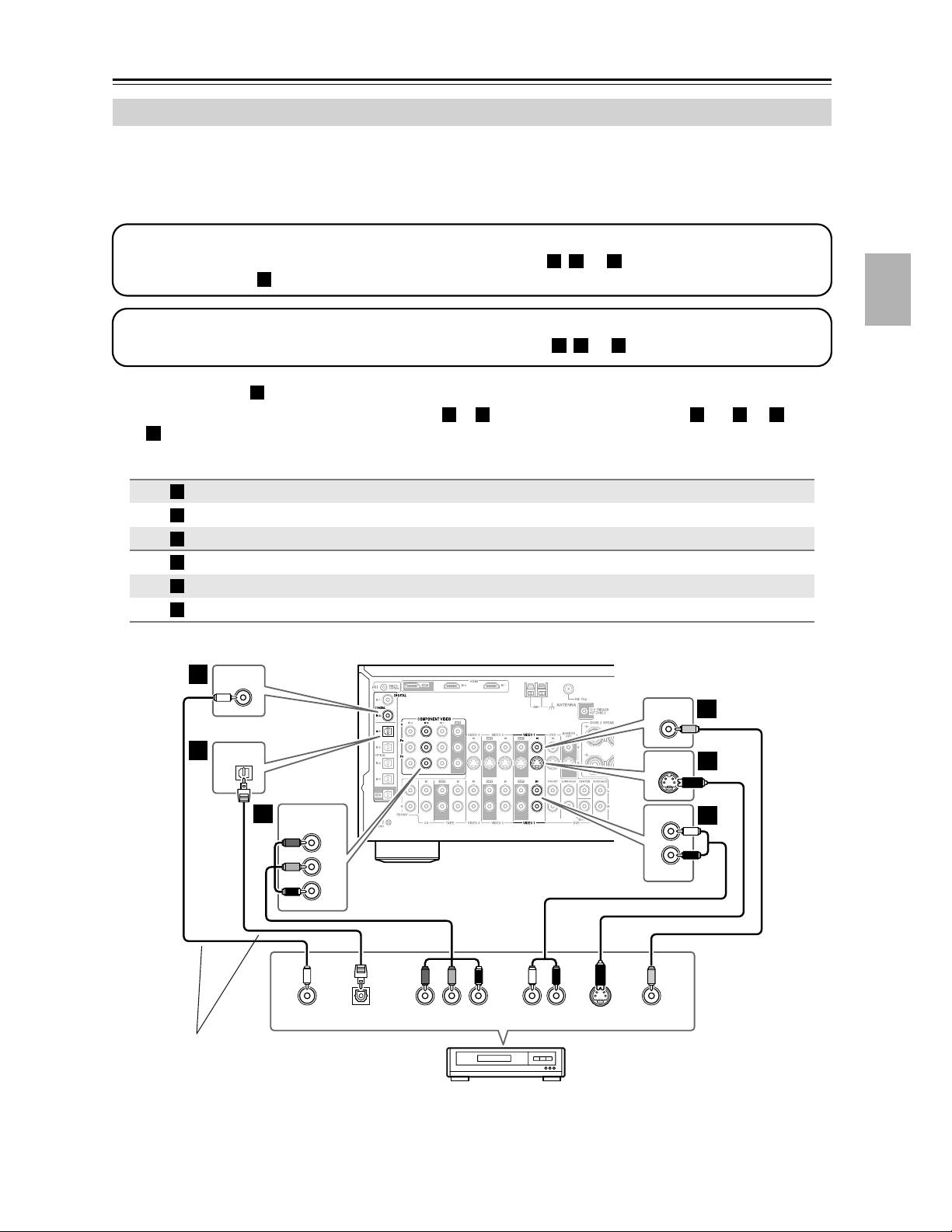
In addition to video playback, with this hookup, you can use your VCR’s tuner to listen to your favorite TV programs
via the AV receiver, useful if your TV has no audio outputs.
If you have two video recorders (e.g., a VCR and a DVD recorder), connect one recorder to the VIDEO 1 IN jacks, as
shown here, and connect the other recorder to the VIDEO 2 IN jacks in the same way.
• With connection , you can listen to the VCR or DVD recorder even in Zone 2.
• To enjoy Dolby Digital and DTS, use connection or . (To listen in Zone 2 as well, use and , or and
.)
Connecting a VCR or DVD Recorder for Playback
Connection AV receiver Signal flow VCR or DVD recorder Picture quality
COMPONENT VIDEO IN 2
⇐
Component video output Best
VIDEO 1 IN S
⇐
S-Video output Better
VIDEO 1 IN V
⇐
Composite video output Standard
VIDEO 1 IN L/R
⇐
Analog audio L/R output
DIGITAL COAXIAL IN 2
⇐
Digital coaxial output
DIGITAL OPTICAL IN 1
⇐
Digital optical output
Step 1: Video Connection
Choose a video connection that matches your VCR or DVD recorder ( , , or
), and then make the connection.
If you use connection , you must connect the AV receiver to your TV with the same type of connection.
A B C
A
Step 2: Audio Connection
Choose an audio connection that matches your VCR or DVD recorder ( , , or ), and then make the connection.
a b c
a
b c a b a
c
A
B
C
a
b
c
COAXIAL
IN 2
YCOAXIAL
OUT
PB
COMPONENT VIDEO OUT
P
R S VIDEO
OUT
AUDIO
OUT
VIDEO
OUT
VIDEO 1
IN
V
S
VIDEO 1
IN
LR
OPTICAL
OUT
OPTICAL
IN 1
Y
P
B
PR
COMPONENT VIDEO
IN 2
L
R
IN
VIDEO 1
b
c
A
B
C
B
a
C
VCR,
DVD recorder
Connect one
or the other
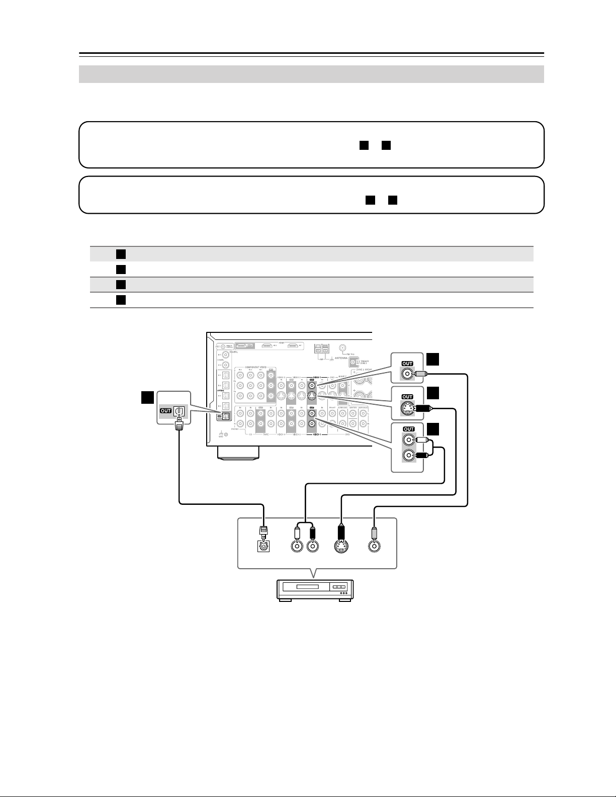
30
Connecting Your Components—Continued
If you have two video recorders (e.g., a VCR and a DVD recorder), connect one recorder to the VIDEO 1 OUT jacks,
as shown here, and connect the other recorder to the VIDEO 2 OUT jacks in the same way.
Connecting a VCR or DVD Recorder for Recording
Connection AV receiver Signal flow VCR or DVD recorder Picture quality
VIDEO 1 OUT S
⇒
S-Video input Better
VIDEO 1 OUT V
⇒
Composite video input Standard
VIDEO 1 OUT L/R
⇒
Audio L/R input
DIGITAL OPTICAL OUT
⇒
Digital optical input
Step 1: Video Connection
Choose a video connection that matches your VCR or DVD recorder ( or ), and then make the connection. The
video source to be recorded must be connected to the AV receiver via the same type of connection.
A B
Step 2: Audio Connection
Choose an audio connection that matches your VCR or DVD recorder ( or ), and then make the connection.
a b
A
B
a
b
S VIDEO
IN
AUDIO
IN
VIDEO
IN
VIDEO 1
VIDEO 1
V
S
LR
OPTICAL
IN
OPTICAL
L
R
VIDEO 1
b
B
C
A
a
B
VCR,
DVD recorder
Loading...