


TX-8211
Table of contents
 Loading...
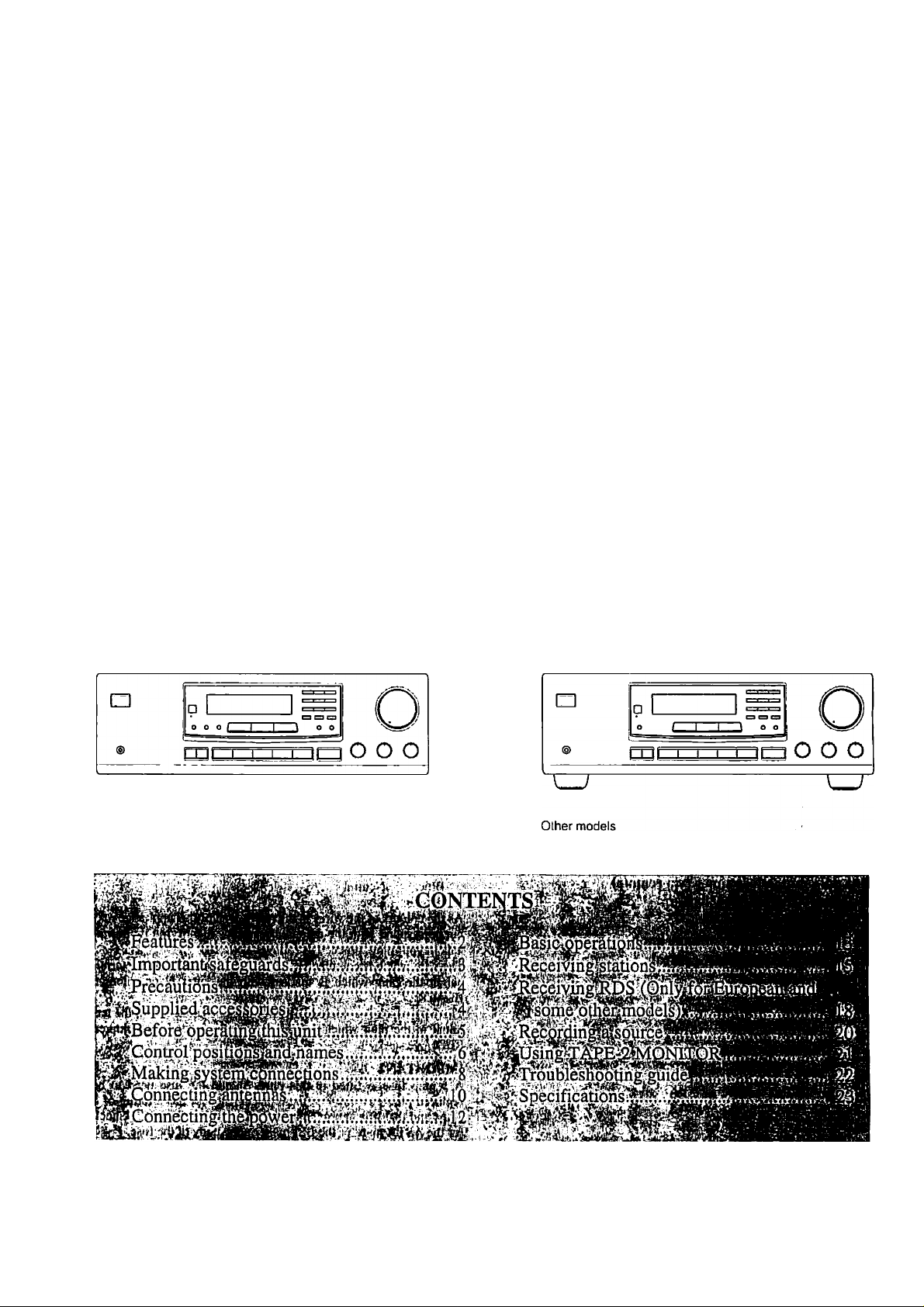
TX-8211
FM Stereo/AM Receiver
Instruction Manual
O“
European and some other models

Thank you for purchasing the Onkyo
TX-821 I FM Slereo/AM Receiver.
Please read this manual thoroughly before making con
nections and operating the unit.
Following the instructions in this manual will enable
you to obtain optimum performance and listening
enjoyment from your new Receiver.
Please retain this manual for future reference.
FOR U.S.A. MODEL
Note to CATV system installer:
• This reminder is provided to call the CATV system installer’s
attention to Section 820-40 of the NEC which provides guide
lines for proper grounding and, in particular, specifies that the
cable ground shall be coimecied to the grounding system of the
building, as clo.se to the point of cable entry as practical.
FOR^ANADIAN MODEL i^ y
POUR LEiiMODEUE CANADiEN^ ^'
Features
I Power output
USA & Canadian models:
50 watts per channel, min RMS, at 8 ohms, both
channels driven from 20 Hz to 20 kHz, with no
more than 0.08% Till).
European models:
2 X 70 watts at 4 ohms, 1 kHz (DIN)
Asian models:
2 X 00 watts at 4 ohm.s, 1 kHz (EIAJ)
I Discrete output stage circuits for true high-current,
low-impedance drive
I
Costly, high-quality parts such as large power tran
sistors, an oversized isolated transformer and heavyduty extruded heat sink makes it possible to accu
rately and effortlessly drive 4-ohm s|)eakers (rare for
a receiver)
I
4 Audio inputs
I
A/B Speaker selector and outputs
I
Cassette tape dubbing capability
I’
Selective tone control
I
2-Mode APR (Automatic Precision Reception) (local/
DX, aulo/inono)
I
30 FM/AM random presets
I
Preset scan tuning
I
3 Station group presets (10 stations per group)
I
RDS with PS, 1*TY, RT, I P (European and some
other models only)
I Direct access tuning
I Motor-driven, precision volume control
I Headphone jack
I Audio mute, sleep timer (via remote)
I Battery-free memory backup
I New non-resonant feel
I New slip-free rotary volume knob
I Rl Compatible remote control
• For models having a power cord with a polarized plug.
CAUTION: TO prevent electric shock, ma tch
WIDE BLADE OF PLUG TO WIDE SLOT, FULLY INSERT.
• Sur les modèles dont la fiche est polarisée.
ATTENTION: pour éviter les chocs élec
triques, INTRODUIRE LA LAME LA PLUS LARGE DE LA
FICHE DANS LA BORNE CORRESPONDANTE DE LA
PRISE ET POUSSER JUSQU'AU FOND.
FOR EUROPEAN MODEL;
Declaration of Conformity
We. ONKYO EUROPE
ELECTRONICS GMBH
INDUSTRIESTRASSE 18/20
82IIOGERMERING.
GERMANY
declare in own responsibility, that the ONKYO prrxluct de.scribed
in this instruction inanu:il is in compliance with the corresponding
technical standards such ;is EN550I3.EN5.V020.EN60555-2,
EN60065
GER.MERING.GERMANY
H. YAMAZOE
ONKYO EUROPE ELECTRONICS GMBH
r,n •■'Wf'- -i
......
¿l ATTENTION FOR BRITISH MODEL ,
Replacement and mounting of an AC plug on the power supply
cord of this unit should be perfomied only by qualified .service
personnel.
IMPORTANT:
The wires in the mains lead are coloured in accordance with the
following code:
Blue: Neutral
Brown: Live
As the colours of the wires in the mains lead of this appliance may
not correspond with the coloured markings identifying the termi
nals in your plug, proceed as follows:
The wire which is coloured BLUE must be connected to the termi
nal in the plug which is marked with the letter N or coloured
BLACK. '
The wire which is coloured BROWN must be connected to the ter
minal in the plug which is nnirked with the letter L or coloured
RED.
IMPORTANT
A 5 amp fu.se is fitted in this plug. Should the fuse need to be
replaced please ensure that the replacement-fu.se has a rating of 5
amps and that it is approved by ASTA or BSI to BS 1362. Check
for the ASTA mark or the BSI mark on the body of the fuse.
IF THE FITTED MOULDED PLUG IS UNSUITABLE FOR
THE SOCKET OUTLET IN YOUR HOME THEN THE FUSE
SHOULD BE REMOVED AND THE PLUG CUT OFF AND
DISPOSED Of- SAFELY. THERE IS A DANGER OF SEVERE
ELECTRICAL SHOCK IF THE CUT OFF PLUG IS INSERTED
INTO ANY 13 AMP SOCKET.
If ill any doubt please consult a iiuulilled electrician.
“WARNING”
•TO REDUCE THE RISK OF FIRE OR ELECTRIC SHOCK,
DO NOT EXPOSE THIS APPLIANCE TO RAIN OR MOIS
TURE."
CAUTION:
"TO REDUCE THE RISK OF ELECTRIC SHOCK. DO NOT
REMOVE COVER (OR BACK). NO USER-SERVICEABLE
PARTS INSIDE. REFER SERVICING TO QUALIFIED SER
VICE PERSONNEL."
Important safeguards
1. Read Instructions - All the safety ami operating insirueiions
.should be read before the appliance i.s operated.
2. Retain Instructions - The safely and operating instructions .should
be retained for fulure reference.
3. Heed Warnings - All warnings on the appUimee and in the operat
ing instructions sliould be adhered to.
4. Follow Instructions - All operating and u.se instructions should be
followed.
5. Water and Moisture - Tlie appliance should not be u.sed near
water - for example, near a bathtub, washbowl, kitchen sink, laundry
tub, in a wet basement, or near a swimming pool, and the like.
6. Carts and Stands - The appliance should be used only with a can
or stand that is recommended by the manufacturer.
6A. An appliance and cart combination
should be moved with care. Quick
stop.s, excessive lorce, and uneven PonTAOLE cart warning
surfaces may cause the appliance
and earl conihination to overturn.
WARNING
RISK OF ELECTRIC SHOCK
A
14. Power Lilies - An outdoor antenna should be located away from
power lines.
15. Nonuse Periods - The power cord of the appliance should be
unplugged from the outlet when left unused for a long period of time.
16. Object and Liquid Entry - Care should be taken so that objects
do not fall and liquids are not spilled into the enclosure through open
ings.
17. Damtige Requiring Service-The appliance should lie .serviced
by qualilieil service personnel when:
.A. The power-supply cord or the plug has been damaged; or
13. Objects have fallen, or liquid has been spilled into the appliance;
or
C. The appliance has been exposed to rain; or
D. The tippliance does not appear to operate normally or exhibits a
marked change in performance; or
E. The appliance Inis been dropped, or the enclosure damaged.
18. Servicing - The ii.ser .should not attempt to service the appliance
beyond that described in the operating instructions. .All other .servicing
should be referred ni qualified service personnel.
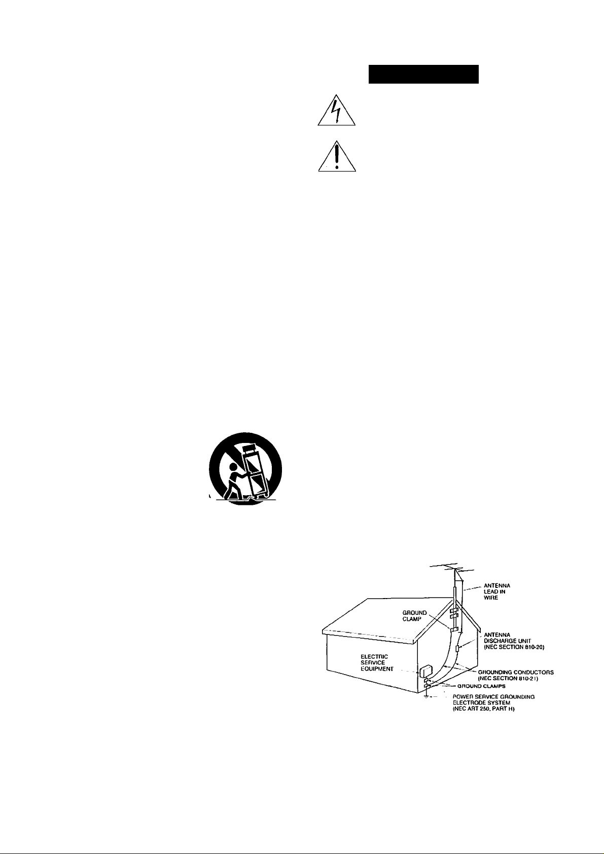
19. Outdoor Antenna Grounding - If an outside antenna is con
nected to the receiver, be sure the antenna system is grounded so as to
provide some proteelion against voltage surges and built up sialic
charges. Article 8 !0 of the National lileclrical Code, ANSI/NIT’A 70,
provides information with regard to proper grounding of the mtisl and
.supporting structure, grounding of the lead-in wire to an antenna dis
charge unit, size of grounding eondiiclors, location of the antenna-dis
charge unit, connection to grounding electrodes, and requirements for
the grounding eleeirode. See Figure 73.1.
DO NOT OPEN
The lightning flash with arrowhead symbot, within
an equilateral triangle, is intended to atert the user
to the presence of “dangerous voltage" within thoi
product's enclosure that may be of sufficient magni
tude to constitute a risk of etectric shock to persons.
The exclamation point within an equilateral triangle
is intended to alert the user to the presence of
important operating and maintenance (servicing)
instructions in the literature accompanying the
product.
A
7. W'all or Ceiling Mounting- The appliance should be mounted to
a wall or ceiling only as recommended by the manufacturer.
8. Ventilation - The appliance should be situated so that its locatioiT or
position does not interfere with its proper ventilation. For example,
the appliance should not be situated on a l>ed,’.sofa, rug, or similar sur
face that may block the ventilation openings; or if placed in a built-in
insiallalion. such as a book case or cabinet ihtit nitty impede the flow
of air through the ventilation ti|K-nings. there .shoiihl lie free space of at
least 20 ctii and open up behitid the appliance.
9.
lletlt -The appliaticc should Ire situated away from heat sources sucfi
as radiators, heal registers, stoves, or other applititices (iticluditig
amplifiers) Ihal produce heal.
10
Power Sources - The appliance should be connected to a power
sitpply only of the type de.scribed in the operalitig imslruciions or as
marked on the appliance.
II
I’olari/.lltioil - If the applitincc is provided with a polarized plug
havitig one blade wider than the other, please reat.1 the followitig infor
mation: The polarizalioti of the plug is a safely feature. The polarized
plug will only lit the outlet one way. If the plug does not lit fully itilo
the outlet, try reversing it. If there is still trouble insciling it, the user
should seek the services of a i|ualilied electrician. Under no circum
stances should the user attempt to defeat the pohnT7.ulion of the plug.
12. Power-Cord Protection - Power-supply cords should be routed so
that they are not likely to be walked on or pinched by items placed
U(ion or against them, especially near plugs, convenience receptticles.
and the point where they exit from the appliance.
13. Cleuning-Thc appliance should be cleaned only as recommended
by the manufacturer.
FIGURE 73.1:
EXAMPLE OF ANTTsNNA GROUNDING
N.ATTONAL ELECTRICAL CODE
NEC - NATIONAL ELECTRICAL CODE
SZSSSA
AS PER
Precautions
1. Warranty Claim
You can find the serial number on the rear panel. In case of war
ranty claim, please report this number.
2. Recording Copyright
Recording of copyrighted material for other than personal use is
illegal without permission of the copyright holder.
3. AC Fuse
The fuse is located inside the chassis and is not user-serviceable.
If power does not come on, contact your Onkyo authorized service
station.
4. Care
From time to time you should wipe the front and re;ir panels and
the cabinet with a soft cloth. For heavier dirt, dampen a .soft cloth
in a weak solution of mild detergent and water, wring it out dry.
and wipe off the dirt. Following this, dry immediately with a clean
cloth. Do not use rough material, thinners, alcohol or other chemi
cal solvents or cloths since these could damage the finish or
remove the panel lettering.
5. Power
WARNING
I3EFORE PLUGGING IN THE UNIT FOR THE FIRST TIME,
READ THE FOLLOWING SECTION CAREFULLY.
• Some models are designed for use only with the power supply
voltage of the region where they arc sold.
European and Ausiralian inodelsiAC 230V. 50H/.
U.S. and Canadian models; AC 120V, 60Hz
Worldwide model: AC 220-230V/I20V swilchabic,
50/60HZ
Other: AC 220V, 60Hz
• Voltage Selector (Rear Panel)
Worldwide models are equipped with a voltage selector to con-
, foiln to local power supplies. Be sure to set this switch to
match the voltage of the power supply in your area before
plugging in the unit. (See page 5.) Models wilhout a voltage
.selector can only be u.sed in areas where the power supply is
the same as that of the unit.
• The power does not shut off completely by just turning the
power off. So power cord should be removed froiii AC outlet
when not in use for a prolonged time.
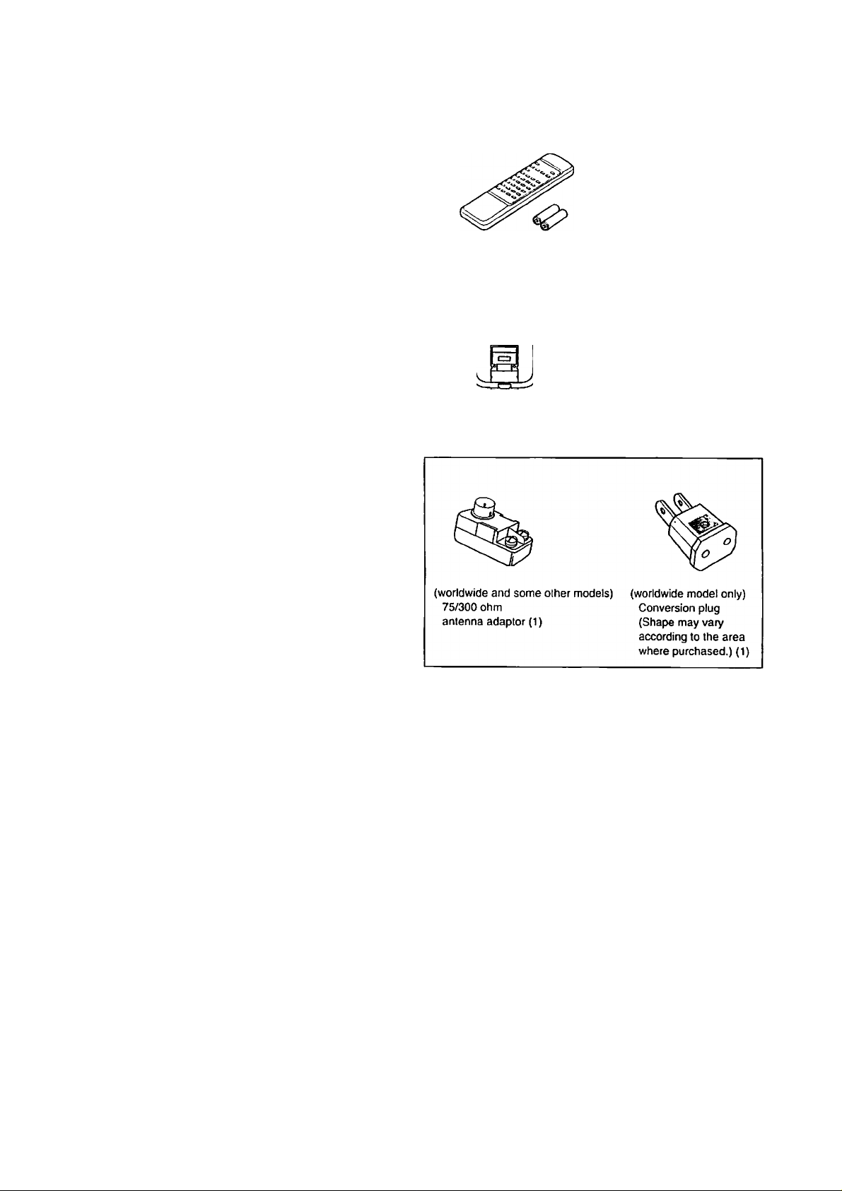
Supplied accessories
Remote control RC-330S (1)
Battery (size AA. R6, or UM-3) (2)
AM loop antenna (1)
T-shaped FM antenna (1)
Memory Preservation
This unit does not require memory preservation batteries. A built-in
memory power back-up system preserves the contents of the mem
ory during power failures and even when the unit is unplugged. The
unit must be plugged in order to charge the back-up .system.
The memory preservation period after the unit has been unplugged
varies depending on climate and placement of the unit. On the aver-
iige, memory contents are protected over a period of a few weeks
after the last lime the unit has been unplugged. This [>eriod is
shorter when the unit is exposed to a highly humid climate.
Before operating this unit
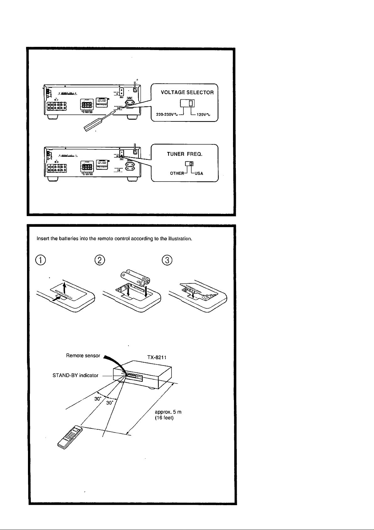
Setting the voltage selector tf'i (worldwide model only), "' ’"f.
. Deteiniine the proper voltage for your
mea: 220 - 230 V or 120 V.
. If the setting on the voltage selector is
not correct, insert a screwdriver into the
groove in the switch and slide the
switch completely to the right (120 V)
or the left (220 ~ 230 V), whichever is
appropriate.
Setting thatuh|ng>tep[^^ . ^
: frequency''''
i: (worldwide rriodel only) •: '
The worldwide model is equipped with a
switch that controls the AM (9 kH/7
10 kHz.) band tuning steps.
Please .set this switch to match the tuning
step frequency in your area.
U.S. & Canada: USA
Other areas: OTHER
Using the remote control
The following information will help you
get optimal use from the remote control.
• Place this unit away from direct bright
light which c:in prevent proper opera
tion of the remote control.
• Mttke sure audio rack doors do not have
tinted glass. Placing this unit behind
such a door may prevent proper remote
control operation.
Loading the batteries , •i
Remove the battery compartment cover by
opening it as shown in the illOistration.
Load two AA (R6 or UM-3)-size batteries
into the remote control with the plus (+)
and minus (-) tertninals positioned as indi
cated by the diagram inside the battery
compartment, then close the cover.
• Immediately remove empty batteries to
avoitl corrosion damage.
• To avoid potential conosion damage,
never mix old batteries with new ones.
• The manganese batteries supplied with
this unit have a .service life of approxi-
mtitely six months, dependitig on the
frequency of use.
• The TX-8211 comes equipped with two
AA (R6 or UM-3) manganese batteries,
but we recommend that long-life AA
(LR6 or AM-3)-size alkaline batteries
be used when replacing the batteries.
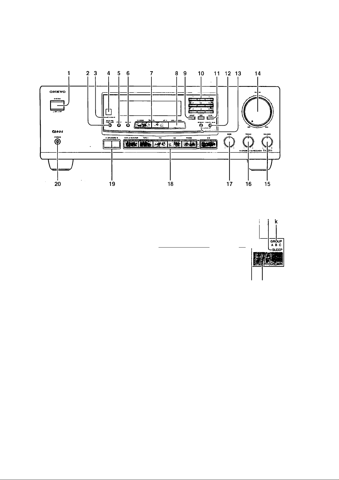
Control positions and names
other than USA & Canadian model
USA and Canadian model
1
For more information about buttons or
knobs, turn to the page number listed in [ ].
1. POWER (or SYSTEM) switch
112J
2. SELECTIVE I'ONE CONT
button [13]
3. STAND-BY indicator |12|
4. Remote sensor [5]
5. P l'YAl'P button [19]
(Only for European and some
other models)
6. DISPLAY button [19]
(Only for European and some
other models)
7. ◄ DOWN, UP ► TUNING
buttons [15]
8. DIRECT TUNING button [15]
Display
ЛГгт-тА P R
BF r STEREO
MODEST, MODE
[ЕНП^ЕШЗ
Bini' ПЕНЕ!
SPEAKERS A 8 AUDIO MUTE FM MUTE ► TUNED < MEMORY
'hT-2 monitor! IsTcl ON OFF ^STEREO ^-tlBia
ÌIÉ iWiHWl
mi mi inM miMm /zi^/
9. GROUP button [16,17] b.
10. Number buttons [15-17]
11. SCAN button [17,19] c.
12. FM MUTE/MODE button [16,17] d.
13. MEMORY button [16, 17] e.
14. VOLUME knob] 13] f.
15. BALANCE control knob [13] g.
16. TREBLE control knob [13] h,
17. BASS control knob ]13] i.
18. Input selector buttons 113] .]■
19. SPEAKERS A/B IniUons [ 13] k,
20. 1 leadphouejack]14] 1
: Display
- - — - # —
If (here is a protective Him on the surface R'
of the display which is making it dilTicult
to read the display, remove it.
a. APR indicators
g h
m I
T-2 MONITOR (Tape-2
Monitor) indicator
Speaker selector indicators
AUDIO MUTE indicator
Selective Tone Control indicator
FM MUTE ON/OEF indicator
STEREO indicator
TUNED indicator
MEMORY indicator
SLEEP indicator
(¡ROUP indiciitors
Preset station/sleep timer
displiiy
RDS indicator (Only for
luiropean atid some other models)
Multi function display
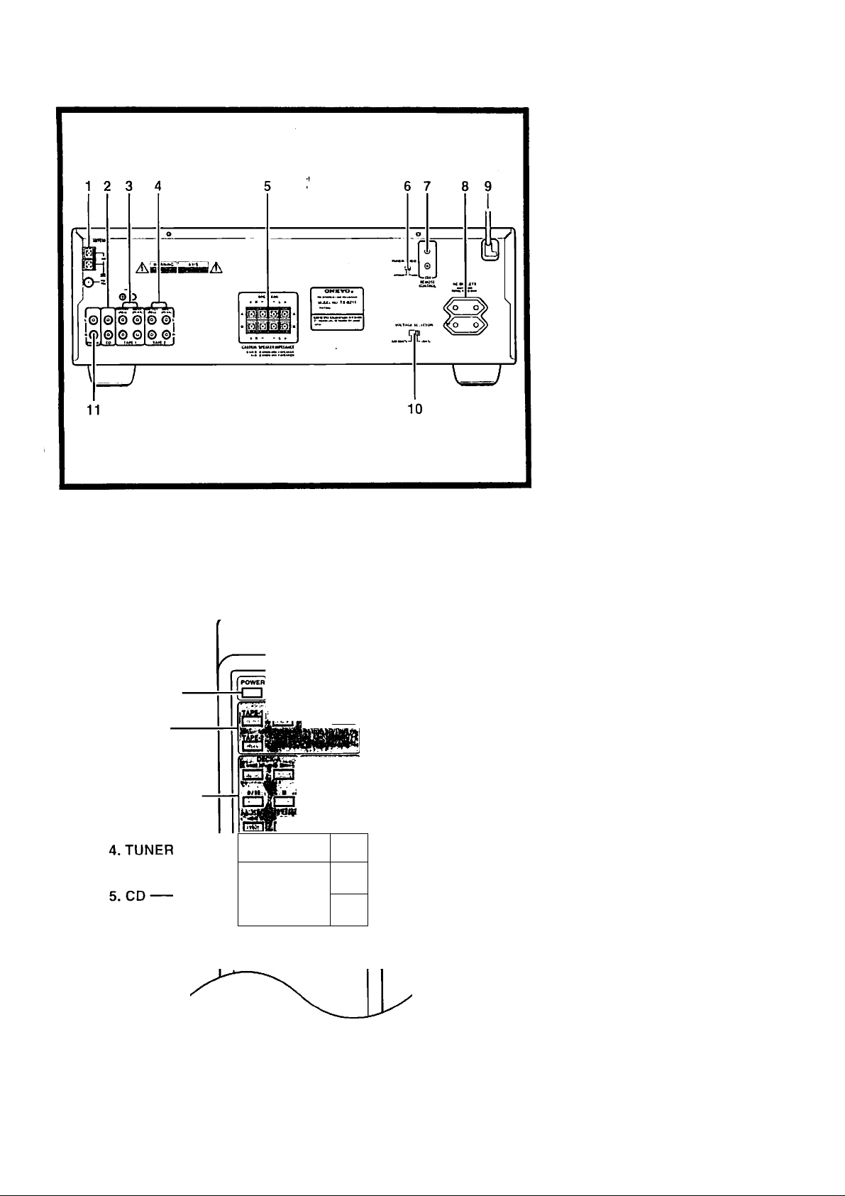
Control positions and names
1. ANTKNNA terminals [llj
2. CD input connectors [8]
3. TAl’E-1/lNl’UT/OUTPUT
connectors [8]
4. TAI»i:-2 INrUT/OUTPU r
connectors [8]
5. SPEAKERS terminals [9]
6. TUNER FREQ. (Tuning Step
Frecpiency) switch [5]
(Worldwide model only)
7. RI REMO TE CONTROL
connectors [8]
8. AC OUTLETS [9]
9. Power supply cord [12]
10. VOLTACiE SELECTOR [5)
(Worldwide model only)
11. PHONO input connectors [8]
1. POWER
2. INPUT
SELECTOR
3. DECK-A/DECK-B
INPUT SIieCTOR :
Ишикщшьси]
P."U .'tWiN. .
ONKYO
REMÜÍE CONTROLLER МС i>n
1
тГТП
MUTING
[ЦЬ
jv'a-.i
CZl
□
T
6. SLEEP
7, MUTING
8. VOLUME
Remote Control i
" t ■'
m
1. POWER hutton [12]
2. INPUT SELECTOR buttons
[13]
4. TUNER operation buttons 117]
GROUP : Group button
.^PRESET ► ;Pivset memory up/
down buttons
6. SLEEP btttton [14]
7. MUTING button [14]
8. VOLUME
When you liiive made the connections
mentioned on page 8, you will be able to
use the Ibllowing buttons.
A/T
buttons [13]
3. Tape deck operation buttons
(DECK-A, DECK-B)
; Reverse play button
: Forward play button
-4-4 : Fast rewind button
► ► : Fast I'oiAvard button
■ : Stop button
•/|| ; Rec/pause button
M: When only a single deck is used,
oix;nite DECK-B.
5. CD player operation buttons
(CD)
■ : Slop button
: Pause button
II
: Play button
: Down button
1-44
; Up button
► ► 1
: Disc button for CD changer
DISC
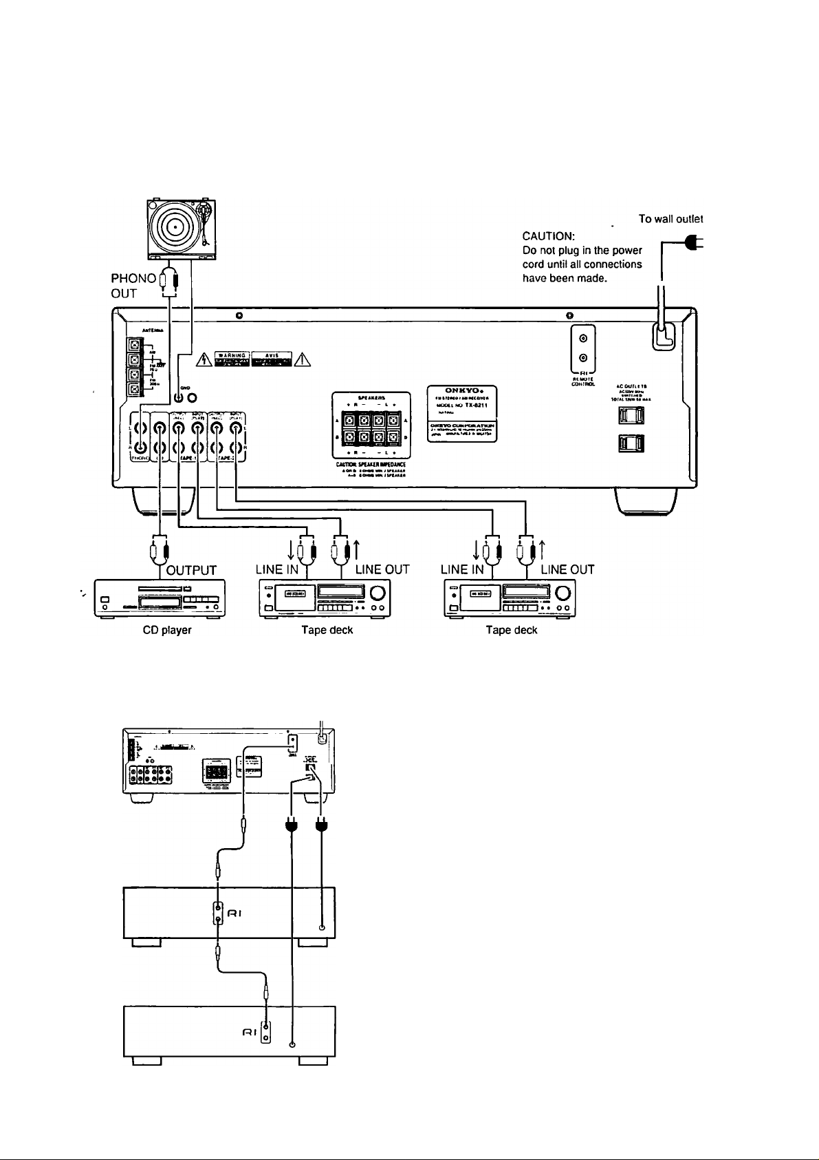
Making system connections
Refer to the insiniciion manual of each component when making connections.
On each pair of connectors, the connector (red and marked R) corresponds to the right
channel and the connector (white and marked L) to the left channel.
Turntable
TX-8211
Cassette tape decks and a compact disc player that are equipped
with an Onkyo Rl connector can be operated using the remote
control included with this unit.
To enable remote control operation of other components, connect
the remote control cable as shown at the left.
NOTK:
• To enable proper remote control operation, both the RI cables
and the audio cables must be connected to the units.
• This unit’s remote control cannot be used to control Onkyo
tnrntable.<t.
• An RI remote control cable equipped with 1/8" (3.5 mm) mini
jacks is included with any other component installed with an
Rl connector.
8
Loading...