


 Loading...
TUNER AMPLIFIER
R-801A
Instruction Manual
TUNER AMPLIFIER
VOLUME
STANDBY |
|
|
|
STANDBY / ON |
DISPLAY MEMORY FM MODE |
INPUT |
TUNING |
PHONES |
CLEAR |
|
ACOUSTIC |
|
|
||
|
|
|
PRESENCE |
R-801A
European models front panel shown.
Thank you for purchasing the ONKYO R-801A Tuner Amplifier.
Please read this manual thoroughly before making any connection or turning on the power.
Follow these instructions to obtain optimum performance and maximum listening enjoyment from your new R-801A. Please retain this manual for future reference.
English
Information Other Operation Preparations Connections using Before
WARNING:
TO REDUCE THE RISK OF FIRE OR ELECTRIC SHOCK, DO NOT EXPOSE THIS APPLIANCE TO RAIN OR MOISTURE.
CAUTION:
TO REDUCE THE RISK OF ELECTRIC SHOCK, DO NOT REMOVE COVER (OR BACK). NO USER-SERVICEABLE PARTS INSIDE. REFER SERVICING TO QUALIFIED SERVICE PERSONNEL.
WARNING |
|
AVIS |
RISK OF ELECTRIC SHOCK |
|
RISQUE DE CHOC ELECTRIQUE |
DO NOT OPEN |
|
NE PAS OUVRIR |
The lightning flash with arrowhead symbol, within an equilateral triangle, is intended to alert the user to the presence of uninsulated “dangerous voltage” within the
product’s enclosure that may be of sufficient magnitude to constitute a risk of electric shock to persons.
The exclamation point within an equilateral triangle is intended to alert the user to the presence of important operating and maintenance (servicing)
instructions in the literature accompanying the appliance.
Important Safeguards
1.Read Instructions – All the safety and operating instructions should be read before the appliance is operated.
2.Retain Instructions – The safety and operating instructions should be retained for future reference.
3.Heed Warnings – All warnings on the appliance and in the operating instructions should be adhered to.
4.Follow Instructions – All operating and use instructions should be followed.
5.Cleaning – Unplug the appliance from the wall outlet before cleaning. The appliance should be cleaned only as recommended by the manufacturer.
6.Attachments – Do not use attachments not recommended by the appliance manufacturer as they may cause hazards.
7.Water and Moisture – Do not use the appliance near water –for example, near a bath tub, wash bowl, kitchen sink, or laundry tub; in a wet basement; or near a swimming pool; and the like.
8.Accessories – Do not place the appliance on an unstable cart, stand, tripod, bracket, or table.The appliance may fall, causing serious injury to a child or adult, and serious damage to the appliance. Use only with a cart, stand, tripod, bracket, or table recommended by the manufacturer, or sold with the appliance. Any mounting of the appliance should follow the manu-
facturer’s instructions, and
should use a mounting PORTABLE CART WARNING
accessory recommended by the manufacturer.
9.An appliance and cart combination should be moved with care. Quick stops, excessive force, and S3125A
uneven surfaces may cause the appliance and cart combination to overturn.
10.Ventilation – Slots and openings in the cabinet are provided for ventilation and to ensure reliable operation of the appliance and to protect it from overheating, and these openings must not be blocked or covered. The openings should never be blocked by placing the appliance on a bed, sofa, rug, or other similar surface. The appliance should not be placed in a built-in installation such as a bookcase or rack unless proper ventilation is provided. There should be free space of at least 20 cm (8 in.) and an opening behind the appliance.
11.Power Sources – The appliance should be operated only from the type of power source indicated on the marking label. If you are not sure of the type of power supply to your home, consult your appliance dealer or local power company.
12.Grounding or Polarization – The appliance may be equipped with a polarized alternating current line plug (a plug having one blade wider than the other). This plug will fit into the power outlet only one way. This is a safety feature. If you are unable to insert the plug fully into the outlet, try reversing the plug. If the plug should still fail to fit, contact your electrician to replace your obsolete outlet. Do not defeat the safety purpose of the polarized plug.
13.Power-Cord Protection – Power-supply cords should be routed so that they are not likely to be walked on or pinched by items placed upon or against them, paying particular attention to cords at plugs, convenience receptacles, and the point where they exit from the appliance.
2
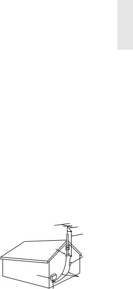
14.Outdoor Antenna Grounding – If an outside antenna or cable system is connected to the appliance, be sure the antenna or cable system is grounded so as to provide some protection against voltage surges and built-up static charges. Article 810 of the National Electrical Code, ANSI/NFPA 70, provides information with regard to proper grounding of the mast and supporting structure, grounding of the leadin wire to an antenna-discharge unit, size of grounding conductors, location of antenna-discharge unit, connection to grounding electrodes, and requirements for the grounding electrode. See Figure 1.
15.Lightning – For added protection for the appliance during a lightning storm, or when it is left unattended and unused for long periods of time, unplug it from the wall outlet and disconnect the antenna or cable system. This will prevent damage to the appliance due to lightning and power-line surges.
16.Power Lines – An outside antenna system should not be located in the vicinity of overhead power lines or other electric light or power circuits, or where it can fall into such power lines or circuits. When installing an outside antenna system, extreme care should be taken to keep from touching such power lines or circuits as contact with them might be fatal.
17.Overloading – Do not overload wall outlets, extension cords, or integral convenience receptacles as this can result in a risk of fire or electric shock.
18.Object and Liquid Entry – Never push objects of any kind into the appliance through openings as they may touch dangerous voltage points or short-out parts that could result in a fire or electric shock. Never spill liquid of any kind on the appliance.
19.Servicing – Do not attempt to service the appliance yourself as opening or removing covers may expose you to dangerous voltage or other hazards. Refer all servicing to qualified service personnel.
20.Damage Requiring Service – Unplug the appliance form the wall outlet and refer servicing to qualified service personnel under the following conditions:
A.When the power-supply cord or plug is damaged,
B.If liquid has been spilled, or objects have fallen into the appliance,
C.If the appliance has been exposed to rain or water,
D.If the appliance does not operate normally by following the operating instructions. Adjust only those controls that are covered by the operating instructions as an improper adjustment of other controls may result in damage and will often require extensive work by a qualified technician to restore the appliance to its normal operation,
E.If the appliance has been dropped or damaged in any way, and
F.When the appliance exhibits a distinct change in performance – this indicates a need for service.
21.Replacement Parts – When replacement parts are required, be sure the service technician has used replacement parts specified by the manufacturer or have the same characteristics as the original part. Unauthorized substitutions may result in fire, electric shock, or other hazards.
22.Safety Check – Upon completion of any service or repairs to the appliance, ask the service technician to perform safety checks to determine that the appliance is in proper operation condition.
23.Wall or Ceiling Mounting – The appliance should be mounted to a wall or ceiling only as recommended by the manufacturer.
24.Heat – The appliance should be situated away from heat sources such as radiators, heat registers, stoves, or other appliances (including amplifiers) that produce heat.
FIGURE 1:
EXAMPLE OF ANTENNA GROUNDING AS PER NATIONAL ELECTRICAL CODE, ANSI/NFPA 70
ANTENNA
LEAD IN
WIRE
GROUND
CLAMP
ANTENNA DISCHARGE UNIT (NEC SECTION 810-20)
ELECTRIC
SERVICE
EQUIPMENT
GROUNDING CONDUCTORS (NEC SECTION 810-21)

 GROUND CLAMPS

 POWER SERVICE GROUNDING
ELECTRODE SYSTEM (NEC ART 250, PART H)
NEC – NATIONAL ELECTRICAL CODE
S2898A
3

Precautions
1. Recording Copyright
Recording of copyrighted material for other than personal use is illegal without permission of the copyright holder.
2. AC Fuse
The fuse is located inside the chassis and is not user-serviceable. If power does not come on, contact your Onkyo authorized service station.
3. Care
From time to time you should wipe the front and rear panels and the cabinet with a soft cloth. For heavier dirt, dampen a soft cloth in a weak solution of mild detergent and water, wring it out dry, and wipe off the dirt. Following this, dry immediately with a clean cloth. Do not use rough material, thinners, alcohol or other chemical solvents or cloths since these could damage the finish or remove the panel lettering.
4. Power
WARNING
BEFORE PLUGGING IN THE UNIT FOR THE FIRST TIME, READ THE FOLLOWING SECTION CAREFULLY.
The voltage of the available power supply differs according to country or region. Be sure that the power supply voltage of the area where this unit will be used meets the required voltage (e.g., AC 230 V, 50 Hz or AC 120 V, 60 Hz) written on the rear panel.
Setting the STANDBY button to standby does not shut off the power completely. So the power cord should be removed from the AC outlet when the unit is not used for a prolonged time.
For British model
Replacement and mounting of an AC plug on the power supply cord of this unit should be performed only by qualified service personnel.
IMPORTANT
The wires in the mains lead are coloured in accordance with the following code:
Blue : Neutral Brown : Live
As the colours of the wires in the mains lead of this apparatus may not correspond with the coloured markings identifying the terminals in your plug, proceed as follows:
The wire which is coloured blue must be connected to the terminal which is marked with the letter N or coloured black.
The wire which is coloured brown must be connected to the terminal which is marked with the letter L or coloured red.
IMPORTANT
A 5 ampere fuse is fitted in this plug. Should the fuse need to be replaced, please ensure that the replacement fuse has a rating of 5 amperes and that it is approved by ASTA or BSI to BS1362. Check for the ASTA mark or the BSI mark on the body of the fuse.
IF THE FITTED MOULDED PLUG IS UNSUITABLE FOR THE SOCKET OUTLET IN YOUR HOME THEN THE FUSE SHOULD BE REMOVED AND THE PLUG CUT OFF AND DISPOSED OF SAFELY. THERE IS A DANGER OF SEVERE ELECTRICAL SHOCK IF THE CUT OFF PLUG IS INSERTED INTO ANY 13 AMPERE SOCKET.
If in any doubt, please consult a qualified electrician.
4

For U.S. model
Note to CATV system installer:
This reminder is provided to call the CATV system installer’s attention to Article 820-40 of the NEC, ANSI/NFPA 70, which provides guidelines for proper grounding and, in particular, specifies that the cable ground shall be connected to the grounding system of the building, as close to the point of cable entry as practical.
FCC Information for User
CAUTION:
The user changes or modifications not expressly approved by the party responsible for compliance could void the user’s authority to operate the equipment.
NOTE:
This equipment has been tested and found to comply with the limits for a Class B digital device, pursuant to Part 15 of the FCC Rules. These limits are designed to provide reasonable protection against harmful interference in a residential installation. This equipment generates, uses and can radiate radio frequency energy and, if not installed and used in accordance with the instructions, may cause harmful interference to radio communications. However, there is no guarantee that interference will not occur in a particular installation. If this equipment does cause harmful interference to radio or television reception, which can be determined by turning the equipment off and on, the user is encouraged to try to correct the interference by one or more of the following measures:
•Reorient or relocate the receiving antenna.
•Increase the separation between the equipment and receiver.
•Connect the equipment into an outlet on a circuit different from that to which the receiver is connected.
•Consult the dealer or an experienced radio/TV technician for help.
For Canadian model
For models having a power cord with a polarized plug:
CAUTION: TO PREVENT ELECTRIC SHOCK, MATCH WIDE BLADE OF PLUG TO WIDE SLOT, FULLY INSERT.
NOTE:
THIS CLASS B DIGITAL APPARATUS COMPLIES WITH CANADIAN ICES-003.
Modele pour les Canadien
Sur les modèles dont la fiche est polarisée: ATTENTION: POUR ÉVITER LES CHOCS ÉLECTRIQUES, INTRODUIRE LA LAME LA PLUS LARGE DE LA FICHE DANS LA BORNE CORRESPONDANTE DE LA PRISE ET POUSSER JUSQU’AU FOND.
REMARQUE:
CET APPAREIL NUMÉRIQUE DE LA CLASSE B EST CONFORME À LA NORME NMB-003 DU CANADA.
Memory Preservation
This unit does not require memory preservation batteries. A built-in memory power backup system preserves the contents of the memory during power failures and even when the unit is unplugged. The unit must be plugged in order to charge the back-up system.
The memory preservation period after the unit has been unplugged varies depending on climate and placement of the unit. On the average, memory contents are protected over a period of a few weeks after the last time the unit has been unplugged. This period is shorter when the unit is exposed to a highly humid climate.
5
Main Features
• A compact, discrete component with |
• Automatic Scan Tuning (FM only) |
|||
|
155mm (6-1/8") wide |
• |
FM TUNED Indicator |
|
• 24 Watts per channel into 4 ohms DIN |
• Audio Muting (operable via remote con- |
|||
• |
Low impedance drive discrete output |
|
trol) |
|
|
stage |
• |
Battery-free Backup System to Protect |
|
• |
Accoustic Presence |
|
Memory Contents |
|
• RDS (Radio Data System) PS only (Euro- |
• Motor driven Volume control |
|||
|
pean model) |
• |
Head phone Jack |
|
• FM/AM random 30 Stations Preset Tuning |
• |
|
Compatible Remote Control Included |
|
|
||||
• |
Timer Play (Weekday,Weekend),Sleep & |
• Blushed Alminume Front Panel |
||
|
Timer Rec |
|
|
|
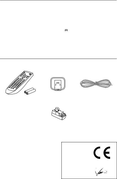
Supplied accessories
Check that the following accessories are supplied with this unit.
|
|
|
|
|
|
FM indoor antenna x 1 |
|
|
|
|
|
|
|
|
|
|
|
|
|
|
|
|
|
|
|
|
|
|
|
|
|
|
|
|
AM loop antenna x 1 |
||||||
Remote controller x 1 (RC-466S)
Batteries x 2
(Size AA, R6, or UM-3)
75/300 ohm antenna adapter x 1 (Available in Asia)
Declaration of Conformity
We, ONKYO EUROPE ELECTRONICS GmbH INDUSTRIESTRASSE 20 82110 GERMERING, GERMANY
declare in own responsibility, that the ONKYO product described in this instruction manual is in compliance with the corresponding technical standards such as EN60065, EN55013, EN55020 and EN61000-3-2, -3-3.
GERMERING, GERMANY
I. MORI
ONKYO EUROPE ELECTRONICS GmbH
6

Table of contents
Before using |
|
Supplied accessories ............................................................................................................ |
6 |
Connections |
|
Connecting to the ONKYO Separate Collection Series components ............................... |
8 |
Connecting to components other than the Separate Collection Series ........................ |
13 |
Connecting speaker systems............................................................................................. |
16 |
Antenna connections ........................................................................................................ |
17 |
Preparations |
|
Preparing the remote controller ...................................................................................... |
20 |
Connecting the AC power cord (mains lead) .................................................................. |
21 |
Operation |
|
Setting the Clock ............................................................................................................... |
22 |
Choosing the required source .......................................................................................... |
27 |
Adjusting the sound.......................................................................................................... |
28 |
Muting/Listening with the headphones .......................................................................... |
29 |
Recording........................................................................................................................... |
30 |
Receiving stations.............................................................................................................. |
31 |
Naming a preset station ................................................................................................... |
34 |
Receiving RDS (European models only) ........................................................................... |
37 |
Using the timer.................................................................................................................. |
38 |
Other Information |
|
Index to parts and controls............................................................................................... |
45 |
Troubleshooting................................................................................................................ |
48 |
Specifications..................................................................................................................... |
50 |
7

Connecting to the ONKYO Separate Collection Series components
This section introduces you to the other Separate Collection Series system components and their convenient system functions, followed by connecting instructions.
The following Separate Collection Series components are commercially available:
• C-701A .............. Compact Disc (CD) Player
•MD-101A ........... Minidisc (MD) Recorder
•CDR-201A ......... Audio CD Recorder
Note that the available components may vary according to the area.
Combination use of the unit with the above system components enables you to operate the following convenient functions:
•Auto Power On
–You can turn on the unit by pressing the STANDBY/ON switch on one of the system components.
–You can turn on all the system components at the same time by pressing the STANDBY/ ON switch on the unit.
You can turn off each component not in use independently afterwards.
•Direct Change
Press the following button on the component you want to operate to switch the unit’s input selector automatically to that component:
–The play button on the CD player, MD recorder or stereo cassette tape deck.
•Remote Control Operation
All the system components can be operated using the supplied remote controller.
•Program Timer
You can operate timer playback and recording using this unit.
•Sleep Timer
You can fall asleep to a music/radio program using this unit.
•CD Dubbing
Simple CD dubbing using an MD recorder or CD recorder is possible with the pressing of a single button. (Refer to the MD-101A or CDR-201A Instruction Manual for more information).
•CD/MD/CDR Synchro Recording
If a connected MD recorder or CD recorder is in recording stand-by mode, pressing the play button on the CD player will automatically start recording. (Refer to the MD-101A, CDR201A or C-701A instruction manual for more information.)
•Dubbing a specific track from CD
You can specify a track on a CD and easily dub it to a connected MD recorder or CDR-201A. (Refer to the MD-101A or CDR-201A instruction manual for more information.)
8
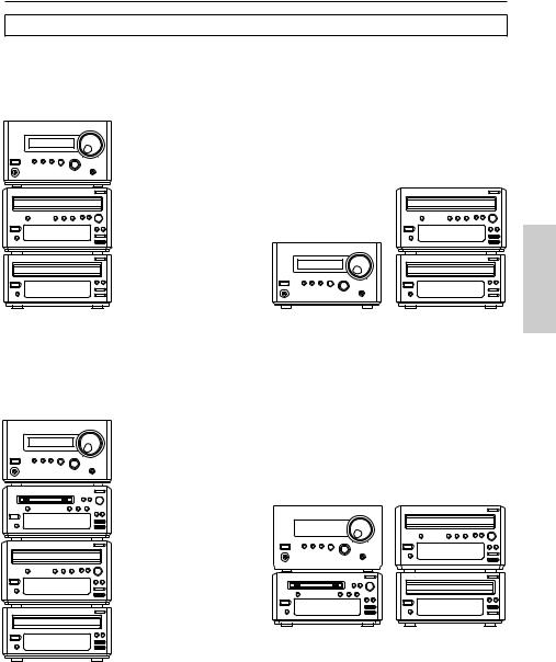
Arranging the system components
Combination example 1
Select the CD player C-701A and CD recorder in addition to this unit. When you arrange these components, stack them as shown below.
Vertical way stacking |
Horizontal way stacking |
This unit (R-801A)
CD recorder (CDR-201A)
CD recorder (CDR-201A)
This unit (R-801A)
CD player (C-701A)
CD player (C-701A)
Combination example 2
Select the CD player C-701A, CD recorder and MD recorder MD-101A in addition to this unit. When you arrange these components, stack them as shown below.
Vertical way stacking |
Horizontal way stacking |
This unit (R-801A)
MD recorder (MD-101A)
|
|
|
|
|
|
|
CD recorder |
|
|
This unit (R-801A) |
|
|
(CDR-201A) |
||
|
|
|
|
|
|
|
|
|
|
|
|
|
|
|
|
|
|
|
|
|
|
|
|
|
|
|
|
|
|
|
|
|
|
|
|
|
|
|
|
CD recorder (CDR-201A)
CD player (C-701A)
MD recorder (MD-101A) CD player (C-701A)
9
Connecting to the ONKYO Separate Collection Series components
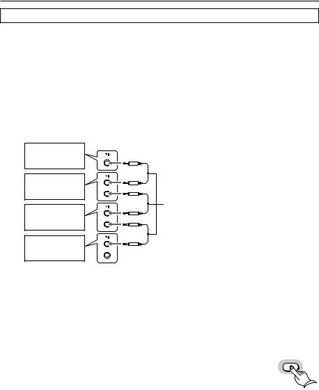
Connecting to the audio connector
Before connecting
•Do not connect the unit’s AC power cord (mains lead) to a wall outlet (the mains) until you have completed all the other connections, including 
 and AC OUTLET connections on page 12 and “Connecting speaker systems” on page 16.
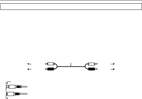
•On each pair of connectors, a red connector (marked R) corresponds to the right channel, and a white connector (marked L) to the left channel. Connect white plugs of audio connection cables to L connectors and connect red plugs of audio connection cables to R connectors.
•Please refer to the instruction manual for each component when you make any connections.
|
|
Audio connection |
|
|
|
cable |
|
To L connector |
(White) |
(White) |
To L connector |
To R connector |
(Red) |
(Red) |
To R connector |
• Insert the plug securely. If the connection is incomplete, noise or malfunction may result.
Improper connection
 Insert completely
•When you use a digital audio optical cable, do not bend it sharply nor coil it tightly.
•Bundling an audio connection cable with the power cord or speaker cord may degrade the sound quality.
•Be sure to use the 
 cable, supplied with each component (except for the R-801A) to connect to the
 remote control connector. If the connection is incomplete, you will be unable to operate the device using the remote controller.
•CD recorders and MD recorders use heat-sensitive parts. Do not place them on top of the amplifier.
10

Note:
To connect both the MD recorder MD-101A and CD player C-701A to the unit:
Connect the MD recorder to the unit following the “Connection for combination example.”
The European model is shown in the following illustrations.
Connections for combination example
CD/DVD |
OUT |
TAPE |
IN |
IN |
|
L |
|
|
R |
|
|
OUT MD |
IN |
OUT CDR/PC IN |
L |
|
|
R |
|
|
ANALOG
INPUT OUTPUT
ANALOG OUTPUT
R L L
R 


ANTENNA |
CD/DVD |
OUT |
TAPE |
|
|
|
|
IN |
IN |
|
SUBWOOFER |
||
|
L |
|
|
|
PRE OUT |
|
|
|
|
|
|
|
|
|
|
|
REMOTE |
|
|
|
|
|
|
CONTROL |
R |
L |
|
AM |
R |
|
|
|
|
|
|
|
|
|
|
|
|
|
OUT MD |
|
OUT CDR/PC |
SPEAKERS |
|
|
|
IN |
IN |
|
|
||
FM 75 |
L |
|
|
CAUTION: |
|
|
|
|
|
|
SPEAKER |
R |
L |
|
|
|
|
IMPEDANCE |
|
|
|
|
|
|
4 OHMS MIN. |
|
|
|
R |
|
|
/ SPEAKER |
|
|
This unit (R-801A)
ANALOG
INPUT OUTPUT
L
Audio
R 

 CD recorder (CDR-201A)
ANALOG OUTPUT |
DIGITAL OUTPUT |
|
|
|
|
|
||
R |
L |
REMOTE |
OPTICAL |
|
|
|
MINIDISC RECORDER |
|
CONTROL |
AC OUTLET |
|
|
|
||||
|
|
|
|
|
|
MODEL NO. MD-101A |
||
|
|
|
AC 230-240V |
50 Hz |
ANALOG |
|
|
|
|
|
|
UNSWITCHED |
|
INPUT |
OUTPUT |
REMOTE |
|
|
|
|
100W MAX. |
|
CONTROL |
|
||
|
|
|
|
|
L |
|
DIGITAL INPUT |
|
|
|
|
|
|
|
|
OPTICAL |
|
COMPACT DISC PLAYER |
|
|
|
|
1 |
2 |
||
|
MODEL NO. C-701A |
|
|
R |
|
|
|
|
|
RATING: AC 230-240V |
|
|
|
|
|
||
|
50 Hz |
8W |
|
|
|
|
|
|
INPUT |
INPUT |
OUTPUT |
1 |
2 |
|
AC OUTLET |
|
OPTICAL |
|
|
|
AC 220 |
|
DIGITAL |
|
AC OUTLET |
|
-230V |
|
|
|
|
|
50 / 60 Hz |
ANALOG |
|
AC 230-240V |
|
|
UNSWITCHED |
REMOTE |
50 Hz |
|
||
100W MAX. |
INPUT |
OUTPUT |
UNSWITCHED |
AUDIO CD RECORDER |
|
|
|
|
CONTROL |
100W MAX. |
MODEL NO. CDR-201A |
L
|
|
|
R |
CD player (C-701A) |
MD recorder |
|
|
|
(MD-101A) |
|
|
DIGITAL OUTPUT |
DIGITAL INPUT |
|
|
OPTICAL |
OPTICAL |
INPUT |
INPUT OUTPUT |
1 |
1 |
2 |
|
|
2 |
|
|
DIGITAL
Optical cable
 : Signal flow
11
Connecting to the ONKYO Separate Collection Series components
Connecting the  connectors and AC OUTLETS
Before connecting
•The hookups on page 11 is needed in addition to the 
 (for remote control operations) and AC OUTLET (for power supply to each component) hookups on this page.
•Each component has two 
 connectors. There is no difference between those connectors. The components may be connected in any order.
•The 
 remote control cable for connecting the
 connectors is supplied with each component (not supplied with the unit).
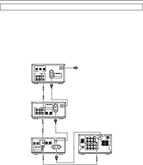
Connections
To use the Clock/Timer function of this unit’s, connect the power cord as shown below and connect the 
 remote control cable and audio connection cables (see page 11). Be sure to connect the power cord of this unit to an AC outlet that supplies continuous power.
CD recorder (CDR-201A)
MD recorder (MD-101A)
CD player (C-701A)
INPUT |
INPUT |
OUTPUT |
|
To wall outlet |
1 |
2 |
|
|
|
|
OPTICAL |
|
|
|
|
DIGITAL |
|
|
|
|
|
|
AC OUTLET |
|
ANALOG |
|
AC 230-240V |
|
|
INPUT |
OUTPUT |
REMOTE |
50 Hz |
|
UNSWITCHED |
AUDIO CD RECORDER |
|||
|
|
CONTROL |
100W MAX. |
MODEL NO. CDR-201A |
L
R
|
|
MINIDISC RECORDER |
|
|
|
|
MODEL NO. MD-101A |
|
|
ANALOG |
REMOTE |
|
|
|
INPUT |
OUTPUT |
CONTROL |
|
AC OUTLET |
L |
|
DIGITAL INPUT |
AC 220 |
|
|
-230V |
|||
|
|
OPTICAL |
|
50 / 60 Hz |
|
|
1 |
2 |
UNSWITCHED |
|
|
100W MAX. |
||
R
ANTENNA |
CD/DVD |
TAPE |
IN |
OUT |
IN |
SUBWOOFER |
|
|
|
PRE OUT |
|
|
|
|
|
|
L |
|
|
|
|
|
|
|
|
|
|
|
|
|
|
|
REMOTE |
|
|
|
ANALOG OUTPUT |
DIGITAL OUTPUT |
|
|
|
|
|
CONTROL |
R |
L |
|||
R |
L |
REMOTE |
OPTICAL |
|
AM |
R |
|
|
|
|
|
|
CONTROL |
AC OUTLET |
|
|
|
|
|
|
|
This unit (R-801A) |
|||
|
|
|
100W MAX. |
|
|
|
|
|
|
SPEAKERS |
|
|
|
|
|
AC 230-240V |
50 Hz |
|
|
MD |
|
OUT CDR/PC |
|
|
|
|
|
|
UNSWITCHED |
|
|
OUT |
IN |
IN |
|
|
||
|
|
|
|
|
FM 75 |
L |
|
|
|
CAUTION: |
|
|
|
|
|
|
|
|
|
|
|
|
SPEAKER |
R |
L |
|
|
|
|
|
|
|
|
|
|
IMPEDANCE |
|
|
COMPACT DISC PLAYER |
|
|
|
|
|
|
|
4 OHMS MIN. |
|
|
||
|
MODEL NO. C-701A |
|
|
|
R |
|
|
|
/ SPEAKER |
|
|
|
|
RATING: AC 230-240V |
|
|
|
|
|
|
|
|
|
|
|
|
50 Hz |
8W |
|
|
|
|
|
|
|
|
|
|
12
Connecting to components other than the Separate Collection Series
Connecting audio/video equipment to audio connectors
Before connecting
•Do not connect the AC power cord (mains lead) to the wall outlet (the mains) until you have completed all the other connections including the sound processor connections on the next page, the 
 connections on page 15, and the speaker connections on page 16.
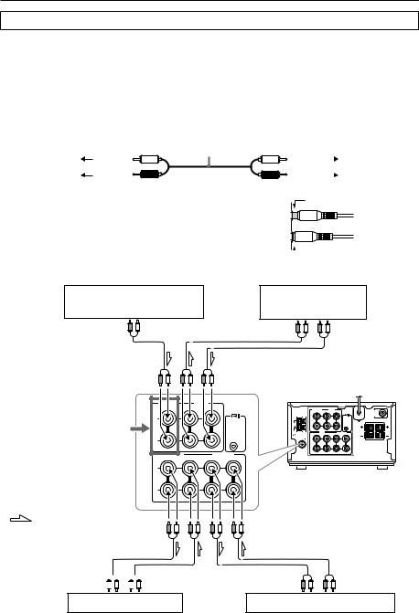
•On each pair of connectors, a red connector (marked R) corresponds to the right channel, and a white connector (marked L) to the left channel.Connect white plugs of audio connection cables to L connectors and connect red plugs of audio connection cables to R connectors.
Audio connection cable
To L connector |
(White) |
To R connector |
(Red) |
• Please refer to the instruction manual for each component when you make any connections.
• Insert the plug securely. If the connection is incomplete, noise or malfunction may result.
(White) |
|
To L connector |
|
||
(Red) |
|
To R connector |
|
Improper connection
 Insert completely
Connections
CD player/DVD player
OUTPUT
Refer to the note on page 15 for information on connecting a CD or DVD player.
: Signal flow
CD/DVD |
OUT |
TAPE |
IN |
IN |
L
REMOTE
CONTROL
R
OUT MD IN |
OUT CDR/PC IN |
L
R
REC 
 PLAY INPUT
 OUTPUT
MD recorder
Stereo cassette tape deck
REC |
|
|
PLAY |
|
|
INPUT |
|
|
OUTPUT |
|
|
This unit (R-801A) |
|||||
ANTENNA |
CD/DVD |
OUT |
TAPE |
|
|
|
IN |
IN |
SUBWOOFER |
||
|
L |
|
|
PRE OUT |
|
|
|
|
|
|
|
|
|
|
REMOTE |
|
|
|
|
|
CONTROL |
R |
L |
AM |
R |
|
|
|
|
|
|
|
|
|
|
|
OUT MD |
|
SPEAKERS |
|
|
|
IN |
OUT CDR/PC IN |
|
|
|
FM 75 |
L |
|
CAUTION: |
|
|
|
|
|
SPEAKER |
R |
L |
|
|
|
IMPEDANCE |
|
|
|
|
|
4 OHMS MIN. |
|
|
|
R |
|
/ SPEAKER |
|
|
(illustration is European model)
REC |
PLAY |
INPUT |
OUTPUT |
CD recorder/audio processor
13
Connecting to components other than the Separate Collection Series
Connecting a subwoofer
Before connecting
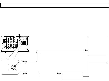
•If your subwoofer isn’t equipped with an amplifier, connect a separate amplifier to the unit first, then connect the subwoofer to that amplifier.
•The SUBWOOFER PRE OUT connector supplies the left and right mixed monaural signals to the subwoofer.
Connections
This unit (R-801A)
ANTENNA |
CD/DVD |
OUT |
TAPE |
|
|
|
When connecting a subwoofer |
|
|
IN |
|
IN |
|
SUBWOOFER |
|||
|
|
|
|
CONTROL |
|
R |
L |
|
|
L |
|
|
|
|
PRE OUT |
|
|
|
|
|
|
REMOTE |
|
|
|
|
AM |
OUT |
MD |
IN |
OUT CDR/PC IN |
SPEAKERS |
|
|
with a built-in amplifier |
|
R |
|
|
|
|
|
|
|
FM 75 |
L |
|
|
|
CAUTION: |
|
|
Subwoofer |
|
R |
|
|
|
SPEAKER |
R |
L |
|
|
|
|
|
/ SPEAKER |
|
|
||
|
|
|
|
|
IMPEDANCE |
|
|
|
|
|
|
|
|
4 OHMS MIN. |
|
|
|
|
|
|
|
|
|
|
|
Audio connection cable |
|
|
|
|
|
|
|
|
When connecting a subwoofer |
SUBWOOFER |
|
|
or |
with no built-in amplifier |
||||
PRE OUT |
|
|
|
|
||||
|
|
|
|
|
|
|
|
Subwoofer |
|
|
|
|
|
|
|
|
Amplifier |
|
|
|
|
|
|
|
|
Audio connection cable |
14
Connecting the  remote control cables
If your other components are made by ONKYO and those components are equipped with 
 connectors, you can control the
 -connected components with the supplied remote controller.
Before connecting
•The unit must be connected in the 
 system hookups for
 control operations.
•Each component has two 
 connectors. There is no difference between these connectors.
•The components may be connected in any order.
•The hookups on the previous page are necessary independently of the 
 system hookups.
The illustration below is an example of a 
 hookup.
Connections
This unit (R-801A)
MD recorder
Audio CD recorder
CD player
 remote control cable (supplied with every ONKYO component that has
  connectors except for the amplifier and receiver)
• This is not an example of stacking the components. For the example, refer to page 9.
Note:
Select “CD” as the input display when you connect a CD player to the R-801A’s CD/DVD connector, and select “DVD” when you connect a DVD player. If you select the wrong input, the system will not operate even if the connection is correct.
Toggling between “CD” and “DVD” for the input display
To toggle between “CD” or “DVD” for the input display, make sure that the
CD/DVD
display indicates “CD” or “DVD,” then press and hold down the CD/DVD button on the remote controller for two seconds or more.
15
Connecting speaker systems
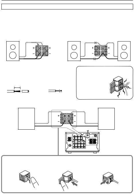
Connecting left and right speakers
Before connecting
•The load impedance of each speaker must be at least 4 ohms.
•Do not use unnecessarily long or extremely thin speaker cords. Otherwise, the DC resistance of the speaker cords may become too high, lowering the damping factor and causing the sound quality to deteriorate.
•Do not connect the speaker cord to the L and R connectors at the same time and do not connect two or more speakers to the same speaker connectors.
SPEAKERS
R L
Preparing the speaker cords for connection
1 Strip 15 mm from |
2 Twist the stripped |
||||||
the end of each |
end of the cord. |
||||||
cord. |
|
|
|
||||
|
|
15mm |
|
|
|
||
|
|
|
|
|
|
|
|
|
|
|
|
|
|
|
|
SPEAKERS |
|
R |
L |
Note |
NO |
|
To prevent dam- |
||
|
||
age to circuits |
|
|
never short-circuit |
|
|
the positive (+) |
|
|
and negative (–) |
|
|
speaker wires. |
|
Connecting the speaker cords to the speaker connectors
Right speaker +
-
SPEAKERS |
|
|
|
|
|
|
|
|
Left |
|
|
|
|
|
|
|
|
speaker |
|
|
|
|
|
|
|
|
|
+ |
|
R |
L |
|
|
|
|
|
|
|
|
|
|
|
|
|
|
|
|
- |
|
|
ANTENNA |
CD/DVD |
OUT |
TAPE |
|
|
|
|
|
|
|
IN |
|
IN |
|
SUBWOOFER |
|
||
|
|
L |
|
|
|
|
PRE OUT |
|
|
|
|
|
|
|
REMOTE |
|
|
|
|
|
|
|
|
|
CONTROL |
R |
L |
|
|
|
AM |
R |
|
|
|
|
|
|
|
|
|
|
|
|
|
|
|
|
|
|
|
|
MD |
|
OUT CDR/PC |
SPEAKERS |
|
|
|
|
|
OUT |
IN |
IN |
|
|
This unit |
||
|
|
|
|
|
|
4 OHMS MIN. |
|
|
|
|
FM 75 |
L |
|
|
|
CAUTION: |
|
|
|
|
|
|
|
|
|
SPEAKER |
R |
L |
|
|
|
|
|
|
|
IMPEDANCE |
|
|
|
|
|
R |
|
|
|
/ SPEAKER |
|
|
|
1 Press down the lever.
2 Insert the wire into the hole.
3Release the lever to replace it.
16
Loading...