


A-933
E
n
Integrated Amplifier
A-933
Instruction Manual
Thank you for purchasing an Onkyo Integrated Ampli-
fier. Please read this manual thoroughly before making
connections and plugging in the unit.
Following the instructions in this manual will enable
you to obtain optimum performance and listening
enjoyment from your new Integrated Amplifier.
Please retain this manual for future reference.
Contents
Introduction.................................... 2
Connections ................................. 10
Enjoying Audio Sources.............. 17
Troubleshooting ........................... 20
Specifications .............................. 22
*EnA93301.fm Page 1 Monday, December 20, 2004 1:23 PM
2
Important Safety Instructions
1. Read these instructions.
2. Keep these instructions.
3. Heed all warnings.
4. Follow all instructions.
5. Do not use this apparatus near water.
6. Clean only with dry cloth.
7. Do not block any ventilation openings. Install in
accordance with the manufacturer’s instructions.
8. Do not install near any heat sources such as radia-
tors, heat registers, stoves, or other apparatus
(including amplifiers) that produce heat.
9. Do not defeat the safety purpose of the polarized or
grounding-type plug. A polarized plug has two
blades with one wider than the other. A grounding
type plug has two blades and a third grounding
prong. The wide blade or the third prong are pro-
vided for your safety. If the provided plug does not
fit into your outlet, consult an electrician for
replacement of the obsolete outlet.
10. Protect the power cord from being walked on or
pinched particularly at plugs, convenience recepta-
cles, and the point where they exit from the appara-
tus.
11. Only use attachments/accessories specified by the
manufacturer.
12.
Use only with the cart, stand,
tripod, bracket, or table spec-
ified by the manufacturer, or
sold with the apparatus.
When a cart is used, use cau-
tion when moving the
cart/apparatus combination
to avoid injury from tip-over.
13. Unplug this apparatus during lightning storms or
when unused for long periods of time.
14. Refer all servicing to qualified service personnel.
Servicing is required when the apparatus has been
damaged in any way, such as power-supply cord or
plug is damaged, liquid has been spilled or objects
have fallen into the apparatus, the apparatus has
been exposed to rain or moisture, does not operate
normally, or has been dropped.
15. Damage Requiring Service
Unplug the apparatus from the wall outlet and refer
servicing to qualified service personnel under the
following conditions:
A. When the power-supply cord or plug is damaged,
B. If liquid has been spilled, or objects have fallen
into the apparatus,
C. If the apparatus has been exposed to rain or
water,
D. If the apparatus does not operate normally by
following the operating instructions. Adjust only
those controls that are covered by the operating
instructions as an improper adjustment of other
controls may result in damage and will often
require extensive work by a qualified technician
to restore the apparatus to its normal operation,
E. If the apparatus has been dropped or damaged in
any way, and
F. When the apparatus exhibits a distinct change in
performance this indicates a need for service.
16. Object and Liquid Entry
Never push objects of any kind into the apparatus
through openings as they may touch dangerous volt-
age points or short-out parts that could result in a
fire or electric shock.
The apparatus shall not be exposed to dripping or
splashing and no objects filled with liquids, such as
vases shall be placed on the apparatus.
Don’t put candles or other burning objects on top of
this unit.
17. Batteries
Always consider the environmental issues and fol-
low local regulations when disposing of batteries.
18. If you install the apparatus in a built-in installation,
such as a bookcase or rack, ensure that there is ade-
quate ventilation.
Leave 20 cm (8") of free space at the top and sides
and 10 cm (4") at the rear. The rear edge of the shelf
or board above the apparatus shall be set 10 cm (4")
away from the rear panel or wall, creating a flue-like
gap for warm air to escape.
WARNING:
TO REDUCE THE RISK OF FIRE OR ELECTRIC
SHOCK, DO NOT EXPOSE THIS APPARATUS
TO RAIN OR MOISTURE.
CAUTION:
TO REDUCE THE RISK OF ELECTRIC SHOCK,
DO NOT REMOVE COVER (OR BACK). NO
USER-SERVICEABLE PARTS INSIDE. REFER
SERVICING TO QUALIFIED SERVICE
PERSONNEL.
The lightning flash with arrowhead symbol, within an
equilateral triangle, is intended to alert the user to the
presence of uninsulated “dangerous voltage” within
the product’s enclosure that may be of sufficient
magnitude to constitute a risk of electric shock to
persons.
The exclamation point within an equilateral triangle is
intended to alert the user to the presence of important
operating and maintenance (servicing) instructions in
the literature accompanying the appliance.
WARNING
RISK OF ELECTRIC SHOCK
DO NOT OPEN
RISQUE DE CHOC ELECTRIQUE
NE PAS
OUVRIR
AVIS
PORTABLE CART WARNING
S3125A
*EnA93302.fm Page 2 Tuesday, January 25, 2005 1:46 PM
3
Precautions
1. Recording Copyright
—Unless it’s for personal use
only, recording copyrighted material is illegal with-
out the permission of the copyright holder.
2. AC Fuse
—The AC fuse inside the unit is not user-
serviceable. If you cannot turn on the unit, contact
your Onkyo dealer.
3. Care
—Occasionally you should dust the unit all
over with a soft cloth. For stubborn stains, use a soft
cloth dampened with a weak solution of mild deter-
gent and water. Dry the unit immediately afterwards
with a clean cloth. Don’t use abrasive cloths, thin-
ners, alcohol, or other chemical solvents, because
they may damage the finish or remove the panel let-
tering.
4. Power
WARNING
BEFORE PLUGGING IN THE UNIT FOR THE
FIRST TIME, READ THE FOLLOWING SEC-
TION CAREFULLY.
AC outlet voltages vary from country to country.
Make sure that the voltage in your area meets the
voltage requirements printed on the unit’s rear panel
(e.g., AC 230 V, 50 Hz or AC 120 V, 60 Hz).
Some models have a voltage selector switch for
compatibility with power systems around the world.
Before you plug in such a model, make sure that the
voltage selector is set to the correct voltage for your
area.
5. Never Touch this Unit with Wet Hands—
Never
handle this unit or its power cord while your hands
are wet or damp. If water or any other liquid gets
inside this unit, have it checked by your Onkyo
dealer.
6. Handling Notes
• If you need to transport this unit, use the original
packaging to pack it how it was when you origi-
nally bought it.
• Do not leave rubber or plastic items on this unit
for a long time, because they may leave marks on
the case.
• This unit’s top and rear panels may get warm
after prolonged use. This is normal.
• If you do not use this unit for a long time, it may
not work properly the next time you turn it on, so
be sure to use it occasionally.
For British models
Replacement and mounting of an AC plug on the power
supply cord of this unit should be performed only by
qualified service personnel.
IMPORTANT
The wires in the mains lead are coloured in accordance
with the following code:
Blue: Neutral
Brown: Live
As the colours of the wires in the mains lead of this
apparatus may not correspond with the coloured mark-
ings identifying the terminals in your plug, proceed as
follows:
The wire which is coloured blue must be connected to
the terminal which is marked with the letter N or
coloured black.
The wire which is coloured brown must be connected to
the terminal which is marked with the letter L or
coloured red.
IMPORTANT
The plug is fitted with an appropriate fuse. If the fuse
needs to be replaced, the replacement fuse must
approved by ASTA or BSI to BS1362 and have the same
ampere rating as that indicated on the plug. Check for
the ASTA mark or the BSI mark on the body of the fuse.
If the power cord’s plug is not suitable for your socket
outlets, cut if off and fit a suitable plug. Fit a suitable
fuse in the plug.
For European Models
Declaration of Conformity
We,
ONKYO EUROPE
ELECTRONICS GmbH
LIEGNITZERSTRASSE 6,
82194 GROEBENZELL,
GERMANY
GROEBENZELL, GERMANY
ONKYO EUROPE ELECTRONICS GmbH
I. MORI
declare in own responsibility, that the ONKYO product
described in this instruction manual is in compliance with the
corresponding technical standards such as EN60065,
EN55013, EN55020 and EN61000-3-2, -3-3.
*EnA93302.fm Page 3 Tuesday, January 25, 2005 1:46 PM
4
Features
❑
Separate design allows various
component configurations
❑
Stereo digital amp featuring Onkyo’s
unique VL (Vector Linear) Digital
technology
❑
Can be used as a power amplifier with a
separate preamp (MAIN IN function)
❑
Super Bass, Bass, and Treble tone
controls
❑
Selectable A/B speaker outputs
❑
Included remote controller can be used
with other Onkyo components
❑
Phono input for connecting a turntable
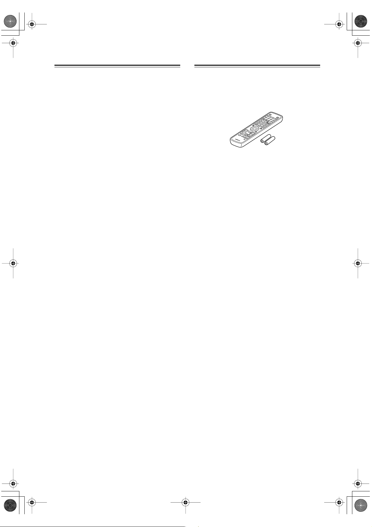
Supplied Accessories
Make sure you have the following accessories:
In catalogs and on packaging, the letter added to the end
of the product name indicates the color of the A-933.
Specifications and operation are the same regardless of
color.
T
A
P
E
/
C
D
R
P
R
E
S
E
T
V
O
L
U
M
E
V
O
L
U
M
E
C
D
M
D
P
R
E
S
E
T
C
L
O
C
K
C
A
L
L
S
L
E
E
P
I
N
P
U
T
O
N
S
T
A
N
D
B
Y
R
C
-
6
1
3
S
>
10
4
2
3
F
M
A
M
C
L
E
A
R
7
8
9
10
/0
5
6
1
G
R
O
U
P
T
I
M
E
R
E
N
T
E
R
ME
MOR
Y
R
E
P
E
A
T
DI
S
P
L
AY
R
AND
O
MP M
ODE
S
C
R
OL
L
M
U
T
I
N
G
Remote controller (RC-613S)
& two batteries (AA/R6)
*EnA93302.fm Page 4 Tuesday, January 25, 2005 1:46 PM
5
Table of Contents
Important Safety Instructions ....................................................................................2
Precautions..................................................................................................................3
Features .......................................................................................................................4
Supplied Accessories ................................................................................................. 4
Table of Contents ........................................................................................................ 5
Front & Rear Panels .................................................................................................... 6
Front Panel............................................................................................................ 6
Rear Panel............................................................................................................. 7
Remote Controller (RC-613S).....................................................................................8
Installing the Batteries ........................................................................................... 9
Using the Remote Controller ................................................................................. 9
Introduction
Connecting the A-933 ...............................................................................................10
About the System Functions................................................................................ 10
Connecting Your Speakers.................................................................................. 11
Connecting a Subwoofer ..................................................................................... 12
Hookup Diagrams for Onkyo Separate Collection............................................... 13
Audio Components.............................................................................................. 14
Connecting a CD player................................................................................... 14
Connecting an MD Recorder............................................................................ 14
Connecting a Tuner.......................................................................................... 14
Connecting a Cassette Deck............................................................................ 14
Connecting a Turntable.................................................................................... 15
Connecting a TV or Other Component with an Audio Output .......................... 15
Connecting a Preamp ......................................................................................15
Connecting Another Component’s Power Cord ............................................... 15
Connecting Components ........................................................................... 16
Connecting the Power Cord............................................................................. 16
Connections
Turning on the A-933........................................................................................... 17
Listening to Components..................................................................................... 17
Selecting Speaker Set A or B........................................................................... 17
Muting the A-933 (remote controller only)........................................................ 18
Using Headphones........................................................................................... 18
Using the Tone Controls...................................................................................... 18
Selecting Tone or Direct Mode......................................................................... 18
Adjusting the Super Bass................................................................................. 18
Adjusting the Bass ...........................................................................................18
Adjusting the Treble ......................................................................................... 18
Using the MAIN IN Function................................................................................ 19
Recording ............................................................................................................ 19
Enjoying Audio Sources
Troubleshooting ........................................................................................................ 20
Specifications ............................................................................................................ 22
Others
*EnA93302.fm Page 5 Tuesday, January 25, 2005 1:46 PM
6
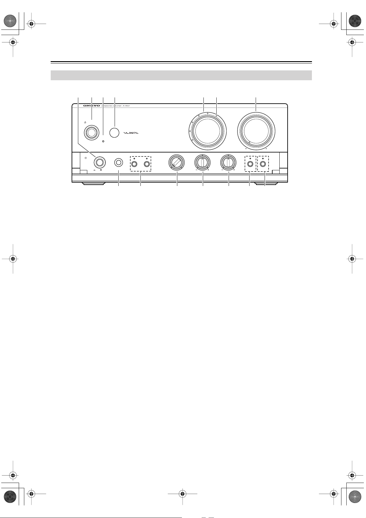
Front & Rear Panels
For detailed information, refer to the pages in parentheses.
A
POWER switch (17)
This is the main power switch. When set to OFF, the
A-933 is completely shutdown. When set to ON, the
A-933 can be set to On or Standby.
B
STANDBY/ON button (17)
This button is used to set the A-933 to On or
Standby. For models with a [POWER] switch, this
button has no effect unless the [POWER] switch is
set to ON.
C
STANDBY indicator (17)
This indicator lights up when the A-933 is in
Standby mode.
D
Remote control sensor (9)
This sensor receives control signals from the remote
controller.
E
Input selector (17)
This control is used to select from the following
input sources: PHONO, TUNER, CD, LINE, MD,
or TAPE/CDR.
F
Input selector indicator (17)
These indicators show the currently selected input
source.
G
VOLUME control (18)
This control is used to adjust the volume of the
A-933.
H
PHONES jack (18)
This phone jack is for connecting a standard pair of
stereo headphones for private listening.
I
SPEAKERS A/B buttons & indicators (17)
These buttons are used to select which speaker set,
A or B, outputs sound. The indicators show if each
speaker set is on or off.
J
SUPER BASS control (18)
This control is for adjusting the level of very-low
bass sounds.
K
BASS control (18)
This control is for adjusting the level of bass
sounds.
L
TREBLE control (18)
This control is for adjusting the level of treble
sounds.
M
TONE(R)/DIRECT(G) button & indicator (18)
This button is used to select Tone mode or Direct
mode. The indicator lights up red (R) in Tone mode;
green (G) in Direct mode.
N
MAIN IN button & indicator (19)
When the A-933 is used as a power amplifier with a
separate preamp, this button is used to set the MAIN
IN function. The indicator lights up blue while the
MAIN IN function is on.
Front Panel
TUNER
PHONO
C D
M D
TAPE /CDR
LINE
STANDBY/ON
STANDBY(R)
ON(G)
POWER
PHONES
TO N E
(
R
)
DIRECT
(
G
)
MAIN IN
BASS TREBLE
SPEAKERS
BA
OFF
ON
SUPER BASS
MAX
24 657
DCBA098
31
*EnA93302.fm Page 6 Tuesday, January 25, 2005 1:46 PM
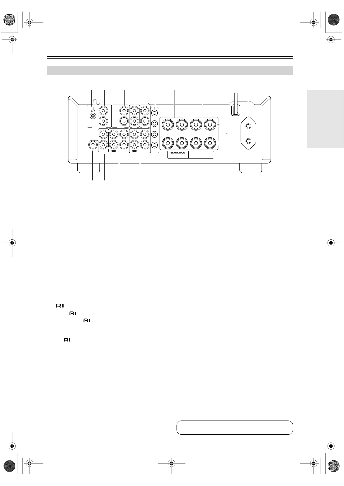
7
Front & Rear Panels
—Continued
A
Grounding terminal
This terminal is for connecting a turntable’s ground
wire.
B
PHONO (MM) input
This analog audio input is for connecting a turntable
with a moving-magnet cartridge.
C
TUNER input
This analog audio input is for connecting a tuner’s
analog audio output.
D
CD input
This analog audio input is for connecting a CD
player’s analog audio output.
E
LINE input
This analog audio input is for connecting a compo-
nent’s analog audio output (TV, etc).
F
REMOTE CONTROL jacks
These (Remote Interactive) jacks can be con-
nected to the jacks on your other Onkyo audio
components. The A-933’s remote controller can
then be used to control all of your components. To
use , you must make an analog audio connection
between the A-933 and each component.
G
SPEAKERS B
These terminal posts are for connecting speaker set
B.
H
SPEAKERS A
These terminal posts are for connecting speaker set
A.
I
AC OUTLET
This AC outlet can be used to supply power to
another audio component. The type of outlet
depends on the country in which you purchased the
A-933.
J
SUBWOOFER PREOUT
This jack is for connecting a powered subwoofer.
K
MAIN IN
This analog audio input is for connecting a separate
preamp when you want to use the A-933 as a power
amplifier.
Caution:
Do not connect a component that does not have an
output volume control, such as a CD player, because
the sound will be output at maximum volume and
may damage the A-933 and your speakers.
L
MD IN/OUT
This analog audio input and output are for connect-
ing an MD recorder with an analog audio input and
output.
M
TAPE/CDR IN/OUT
This analog audio input and output are for connect-
ing a recorder (CD, cassette, etc) with an analog
audio input and output.
Rear Panel
AC OUTLET
UNSWITCHED
TOTAL
100W MAX.
AC 230-240 V
50 Hz
CAUTION: SPEAKER IMPEDANCE
A or B : 4 OHMS MIN. /SPEAKER
A + B : 8 OHMS MIN. /SPEAKER
MODEL NO. A
-
933
INTEGRATED AMPLIFIER
MD
SPEAKERS
R
R
L
R
L
L
R
L
R
L
SUBWOOFER
PREOUT
OUT
IN
OUT
IN
GND
REMOTE
CONTROL
TAPE/CDR
MAIN IN
CD
LINE
TUNER
PHONO (MM)
A
B
R
L
R
L
R
L
132546 8 97
CBA0
See pages 11–16 for connection information
*EnA93302.fm Page 7 Tuesday, January 25, 2005 1:46 PM
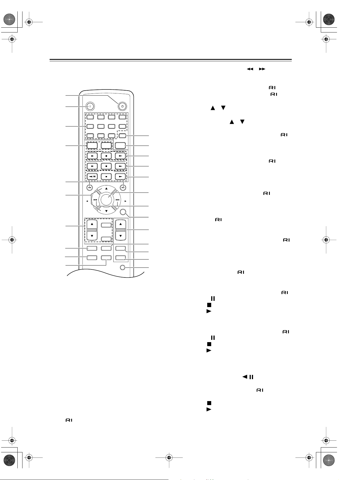
8
Remote Controller (RC-613S)
For detailed information, refer to the pages in parenthe-
ses.
A
STANDBY button (17)
This button is used to set the A-933 to Standby.
B
ON button (17)
This button is used to turn on the A-933.
C
Number buttons
These buttons are used to enter track numbers. To
enter a single-digit number, simply press the corre-
sponding button. The [10/0] button is used to enter
either 10 or 0. The [>10] button is used when enter-
ing 2-digit numbers above 10.
See the instruction manual supplied with each com-
ponent for more information.
D
FM & AM buttons
These buttons are used to select AM or FM on an
Onkyo Separate Collection tuner that’s connected
via .
E
Reverse & Fast Forward [ ]/[ ] buttons
These buttons are used for reverse and fast forward
on an Onkyo Separate Collection CD, MD, cassette,
or CDR component that’s connected via . On
some Onkyo tuners that’re connected via ,
they’re used to change the frequency.
F
VOLUME [ ]/[ ] buttons (18)
These buttons adjust the volume of the A-933.
G
TIMER, Up/Down [ ]/[ ] & ENTER buttons
These buttons set the clock and timer on an Onkyo
Separate Collection tuner that’s connected via .
H
MEMORY button
This button is used to set the memory playback
function on an Onkyo Separate Collection CD, MD,
or CDR component that’s connected via . With
memory playback, you can make a custom program.
I
RANDOM button
This button is used to set the random playback func-
tion on an Onkyo Separate Collection CD, MD, or
CDR component that’s connected via .
J
P MODE button
This button sets the playback mode on an Onkyo
Separate Collection MD or CDR component that’s
connected via .
K
GROUP button
This button selects groups on an Onkyo Separate
Collection MD component that’s connected via .
L
CLEAR button
This button is used to remove the last track from the
memory function program, etc., on an Onkyo Sepa-
rate Collection CD, MD, cassette, or CDR compo-
nent that’s connected via .
M
CD control buttons
These buttons are used to control an Onkyo Sepa-
rate Collection CD player that’s connected via .
Pause
[ ]: Pauses playback
Stop
[ ]: Stops playback
Play
[ ]: Starts playback
N
MD control buttons
These buttons are used to control an Onkyo Sepa-
rate Collection MD player that’s connected via .
Pause
[ ]: Pauses playback
Stop
[ ]: Stops playback
Play
[ ]: Starts playback
O
TAPE/CDR control buttons
For double cassette decks, only Deck B can be con-
trolled.
Reverse Play/Pause
[ / ]: Starts reverse
playback on an Onkyo Separate Collection cas-
sette deck that’s connected via ; pauses play-
back on an Onkyo Separate Collection CDR.
Stop
[ ]: Stops playback
Play
[ ]: Starts playback
P
MUTING button (18)
This button is used to mute the A-933.
TAPE
/
CDR
PRESET
VOLUME
VOLUME
CD
MD
PRESET
CLOCK
CALL
SLEEP
INPUT
ON
STANDBY
R
C
-
613
S
FM AM CLEAR
78
9
10/0
>
10
4
56
231
GROUP
TIMER
ENTER
MEMORY REPEAT DISPLAY
RANDOM P MODE SCROLL
MUTING
2
3
4
5
0
9
8
B
A
C
I
L
M
G
F
J
H
6
7
D
E
K
1
*EnA93302.fm Page 8 Tuesday, January 25, 2005 1:46 PM
 Loading...