


Integrated Stereo Amplifier
A-905TX
Instruction Manual
INTEGRATED STEREO AMPLIFIER
|
|
|
|
|
|
VOLUME |
WIDE RANGE AMP TECHNOLOGY |
|
|
|
|
|
|
|
INPUT |
STANDBY/ON |
CD |
MD |
TUNER |
TAPE |
|
|
|
|
|
|
LINE/ DVD |
CDR/PC |
|
|
|
STANDBY |
|
|
|
|
|
DIRECT |
|
|
|
|
|
|
|
|
|
|
|
|
|
|
|
SOURCE DIRECT |
|
|
BASS |
|
TREBLE |
BALANCE |
DIRECT |
ACOUSTIC |
|
POWER PHONES |
|
|
|
|
|
TONE |
PRESENCE |
ON OFF |
+ |
— |
+ |
L |
R |
|
OFF/1/2 |
— |
|
|
|||||
A-905TX
English
Information Other Operation Preparations Connections using Before
Before using
Thank you for purchasing ...
Thank you for purchasing the ONKYO A-905TX Integrated Stereo Amplifier.
Please read this manual thoroughly before making any connection or turning on the power. Follow these instructions to obtain optimum performance and maximum listening enjoyment from your new A-905TX. Please retain this manual for future reference.
Main Features
∙ |
High-Quality Separate Component |
∙ |
Acoustic Presence Circuit Naturally En- |
∙ WRAT (Wide Range Amp Technology) Circuit |
|
hances the Extreme Low Range |
|
∙ |
Processor In/Out, Subwoofer Pre Out |
∙ |
Source Direct Function |
∙ |
Six-audio Source Inputs |
∙ |
System Control Remote Controller |
Memory Preservation |
|
This unit does not require memory preservation |
The memory preservation period after the unit |
batteries. A built-in memory power back-up sys- |
has been unplugged varies depending on climate |
tem preserves the contents of the memory dur- |
and placement of the unit. On the average, |
ing power failures and even when the unit is un- |
memory contents are protected over a period of |
plugged. The unit must be plugged in order to |
a few weeks after the last time the unit has been |
charge the back-up system. |
unplugged. This period is shorter when the unit |
|
is exposed to a highly humid climate. |
|
|
WARNING:
TO REDUCE THE RISK OF FIRE OR ELECTRIC SHOCK, DO NOT EXPOSE THIS APPLIANCE TO RAIN OR MOISTURE.
CAUTION:
TO REDUCE THE RISK OF ELECTRIC SHOCK, DO NOT REMOVE COVER (OR BACK). NO USER-SERVICEABLE PARTS INSIDE. REFER SERVICING TO QUALIFIED SERVICE PERSONNEL.
WARNING |
|
AVIS |
RISK OF ELECTRIC SHOCK |
|
RISQUE DE CHOC ELECTRIQUE |
DO NOT OPEN |
|
NE PAS OUVRIR |
|
|
|
The lightning flash with arrowhead symbol, within an equilateral triangle, is intended to alert the user to the presence of uninsulated “dangerous voltage” within the product’s enclosure that may
be of sufficient magnitude to constitute a risk of electric shock to persons.
The exclamation point within an equilateral triangle is intended to alert the user to the presence of important operating and maintenance
(servicing) instructions in the literature accompanying the appliance.
2

Important Safeguards
1.Read Instructions – All the safety and operating instructions should be read before the appliance is operated.
2.Retain Instructions – The safety and operating instructions should be retained for future reference.
3.Heed Warnings – All warnings on the appliance and in the operating instructions should be adhered to.
4.Follow Instructions – All operating and use instructions should be followed.
5.Water and Moisture – The appliance should not be used near water – for example, near a bathtub, washbowl, kitchen sink, laundry tub, in a wet basement, or near a swimming pool, and the like.
6.Carts and Stands – The appliance should be used only with a cart or stand that is recommended by the manufacturer.
6A. An appliance and cart combination should be moved with care. Quick stops, excessive force, and uneven surfaces may cause the appliance and cart combination to overturn.
PORTABLE CART WARNING
S3125A
7.Wall or Ceiling Mounting – The appliance should be mounted to a wall or ceiling only as recommended by the manufacturer.
8.Ventilation – The appliance should be situated so that its location or position does not interfere with its proper ventilation. For example, the appliance should not be situated on a bed, sofa, rug, or similar surface that may block the ventilation openings; or if placed in a built-in installation, such as a bookcase or cabinet that may impede the flow of air through the ventilation openings, there should be free space of at least 20 cm (8 in.) and an opening behind the appliance.
9.Heat – The appliance should be situated away from heat sources such as radiators, heat registers, stoves, or other appliances (including amplifiers) that produce heat.
10.Power Sources – The appliance should be connected to a power supply only of the type described in the operating instructions or as marked on the appliance.
11.Polarization – If the appliance is provided with a polarized plug having one blade wider than the other, please read the following information:
The polarization of the plug is a safety feature. The polarized plug will only fit the outlet one way. If the plug does not fit fully into the outlet, try reversing it. If there is still trouble, the user should seek the services of a qualified electrician. Under no circumstances should the user attempt to defeat the polarization of the plug.
12.Power-Cord Protection – Power-supply cords should be routed so that they are not likely to be walked on or pinched by items placed upon or against them, especially near plugs, convenience receptacles, and the point where they exit from the appliance.
13.Cleaning – The appliance should be cleaned only as recommended by the manufacturer.
14.Nonuse Periods – The power cord of the appliance should be unplugged from the outlet when left unused for a long period of time.
15.Object and Liquid Entry – Care should be taken so that objects do not fall and liquids are not spilled into the enclosure through openings.
16.Damage Requiring Service – The appliance should be serviced by qualified service personnel when:
A.The power-supply cord or the plug has been damaged; or
B.Objects have fallen, or liquid has been spilled into the appliance; or
C.The appliance has been exposed to rain; or
D.The appliance does not appear to operate normally or exhibits a marked change in performance; or
E.The appliance has been dropped, or the enclosure damaged.
17.Servicing – The user should not attempt to service the appliance beyond that described in the operating instructions. All other servicing should be referred to qualified service personnel.
using Before
3

Precautions
1. Warranty Claim
You can find the serial number on the rear panel of this unit. In case of warranty claim, please report this number.
2. Recording Copyright
Recording of copyrighted material for other than personal use is illegal without permission of the copyright holder.
3. AC Fuse
The fuse is located inside the chassis and is not user-serviceable. If power does not come on, contact your Onkyo authorized service station.
4. Care
From time to time you should wipe the front and rear panels and the cabinet with a soft cloth. For heavier dirt, dampen a soft cloth in a weak solution of mild detergent and water, wring it out dry, and wipe off the dirt. Following this, dry immediately with a clean cloth. Do not use rough material, thinners, alcohol or other chemical solvents or cloths since these could damage the finish or remove the panel lettering.
5. Power
WARNING
BEFORE PLUGGING IN THE UNIT FOR THE FIRST TIME, READ THE FOLLOWING SECTION CAREFULLY.
The voltage of the available power supply differs according to country or region. Be sure that the power supply voltage of the area where this unit will be used meets the required voltage (e.g., AC 230 V, 50 Hz or AC 120 V, 60 Hz) written on the rear panel.
Declaration of Conformity
We, ONKYO EUROPE ELECTRONICS GmbH INDUSTRIESTRASSE 20 82110 GERMERING, GERMANY
declare in own responsibility, that the ONKYO product described in this instruction manual is in compliance with the corresponding technical standards such as EN60065, EN55013, EN55020 and EN61000-3-2, -3-3. 
GERMERING, GERMANY
A.HORIUCHI
ONKYO EUROPE ELECTRONICS GmbH
For British model
Replacement and mounting of an AC plug on the power supply cord of this unit should be performed only by qualified service personnel.
IMPORTANT
The wires in the mains lead are coloured in accordance with the following code:
Blue : Neutral Brown : Live
As the colours of the wires in the mains lead of this apparatus may not correspond with the coloured markings identifying the terminals in your plug, proceed as follows:
The wire which is coloured blue must be connected to the terminal which is marked with the letter N or coloured black.
The wire which is coloured brown must be connected to the terminal which is marked with the letter L or coloured red.
IMPORTANT
A 5 ampere fuse is fitted in this plug. Should the fuse need to be replaced, please ensure that the replacement fuse has a rating of 5 amperes and that it is approved by ASTA or BSI to BS1362. Check for the ASTA mark or the BSI mark on the body of the fuse.
IF THE FITTED MOULDED PLUG IS UNSUITABLE FOR THE SOCKET OUTLET IN YOUR HOME THEN THE FUSE SHOULD BE REMOVED AND THE PLUG CUT OFF AND DISPOSED OF SAFELY. THERE IS A DANGER OF SEVERE ELECTRICAL SHOCK IF THE CUT OFF PLUG IS INSERTED INTO ANY 13 AMPERE SOCKET. If in any doubt, please consult a qualified electrician.
For Canadian model
For models having a power cord with a polarized
plug:
CAUTION: TO PREVENT ELECTRIC SHOCK, MATCH WIDE BLADE OF PLUG TO WIDE SLOT, FULLY INSERT.
Modele pour les Canadien
Sur les modèles dont la fiche est polarisée: ATTENTION: POUR ÉVITER LES CHOCS
ÉLECTRIQUES, INTRODUIRE LA LAME LA PLUS LARGE DE LA FICHE DANS LA BORNE CORRESPONDANTE DE LA PRISE ET POUSSER JUSQU’AU FOND.
4
Table of contents |
|
Connections |
|
Connecting to the ONKYO Separate Collection Series components .................. |
6 |
Connecting to components other than the Separate Collection Series ............ |
12 |
Connecting speaker systems .......................................................................... |
15 |
Preparations |
|
Preparing the remote controller ...................................................................... |
17 |
Operation |
|
Turning the unit on ........................................................................................ |
18 |
Choosing the required source ........................................................................ |
19 |
Adjusting the sound....................................................................................... |
20 |
Source Direct function/Muting/Listening with the headphones ....................... |
21 |
Recording ...................................................................................................... |
22 |
Other Information |
|
Troubleshooting ............................................................................................. |
23 |
Specifications ................................................................................................. |
24 |
Index to parts and controls ............................................................................. |
25 |
Supplied accessories
Check that the following accessories are supplied with this unit.
using Before
Remote controller x 1 |
Batteries x 2 |
(RC-456S) |
(Size AA, R6, or UM-3) |
5

Connections
Connecting to the ONKYO Separate Collection Series components
This section introduces you to the other Separate Collection Series system components and their convenient system functions, followed by connecting instructions.
The following Separate Collection Series components are commercially available:
•T-405TX ............ Stereo Tuner
•K-505TX ........... Stereo Cassette Tape Deck
•C-705TX ........... Compact Disc (CD) Player (Not available in U.S. and Canada)
•C-707CHX ........ Compact Disc (CD) Changer (Only available in U.S. and Canada)
•MD-105TX ........ Minidisc (MD) Recorder (Not available in U.S. and Canada)
•CDR-205TX ...... Compact Disc (CD) Recorder (available only in part of Asia)
Note that the available components may vary according to the area.
Combination use of the unit with the above system components enables you to operate the following convenient functions:
• Auto Power On
– You can turn on the unit by pressing the STANDBY/ON switch on one of the system components. (The unit's POWER switch must be set to ON.)
– You can turn on all the system components at the same time by pressing the STANDBY/ON switch on the unit. (The unit's POWER switch must be set to ON.)
You can turn off each component not in use independently afterwards.
• Direct Change
Press the following button on the component you want to operate to switch the unit’s input selector automatically to that component:
– |
The play button on the CD player (or changer), MD recorder, or stereo cassette tape deck, or |
||
– |
The PRESET |
/ |
buttons on the tuner. |
• Remote Control Operation
All the system components can be operated using the supplied remote controller. The remote control buttons operate in the same way as the buttons on each component with the same indication.
• Program Timer
You can operate timer playback and recording using T-405TX. (Refer to the T-405TX instruction manual for more information.)
• Sleep Timer
You can fall asleep to a music/radio program using the timer. (Refer to the T-405TX instruction manual for more information.)
• CD Dubbing
Simple CD dubbing using a stereo cassette tape deck or MD recorder is possible with the pressing of a single button (CD dubbing function using an MD recorder is not avalable on the C-707CHX). (Refer to the K-505TX or MD-105TX Instruction Manual for more information).
• CD/MD Synchro Recording
When using a stereo cassette tape deck, MD recorder or CD recorder to record from the CD player or when using a stereo cassette tape deck to record from an MD recorder, you can record with simply starting on a CD player or MD recorder. (Refer to the K-505TX, MD-105TX or CDR-205TX instruction manual for more information.)
• Dubbing a specific track from CD
You can specify a track on a CD and easily dub it to a connected MD recorder or CD recorder. (Refer
to the MD-105TX or CDR-205TX instruction manual for more information.)
6
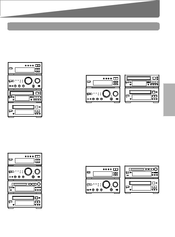
Arranging the system components
Combination example 1
Select the tuner T-405TX, CD player C-705TX (or CD changer C-707CHX), and stereo cassette tape deck K-505TX in addition to this unit. When you arrange these components, stack them as shown below.
Vertical way stacking |
|
Horizontal way stacking |
|
|
Tuner |
|
Tuner |
Stereo cassette tape |
|
(T-405TX) |
||||
(T-405TX) |
deck (K-505TX) |
|||
|
|
|||
Amplifier – this unit |
|
|
||
(A-905TX) |
|
|
||
Stereo cassette tape |
|
|
||
deck |
(K-505TX) |
|
|
|
CD player |
Amplifier – this unit |
CD player |
||
(C-705TX) or |
||||
(A-905TX) |
(C-705TX) or |
|||
CD changer |
||||
|
CD changer |
|||
(C-707CHX) |
|
|||
|
(C-707CHX) |
|||
|
|
|
||
Combination example 2
Select the tuner T-405TX, CD player C-705TX and MD recorder MD-105TX in addition to this unit. When you arrange these components, stack them as shown below.
Vertical way stacking |
Horizontal way stacking |
|
Tuner |
Tuner |
MD recorder |
(T-405TX) |
(T-405TX) |
(MD-105TX) |
Amplifier – this unit |
|
|
(A-905TX) |
|
|
MD recorder |
|
|
(MD-105TX) |
|
|
CD player |
Amplifier – this unit |
CD player |
(C-705TX) |
(A-905TX) |
(C-705TX) |
Tip
In addition to the above combination examples, you can also connect both the MD recorder MD-105TX and stereo cassette tape deck K-505TX with the tuner T-405TX, CD player C-705TX, and this unit.
Information Other Operation Preparations Connections using Before
7
Connecting to the ONKYO Separate Collection Series components
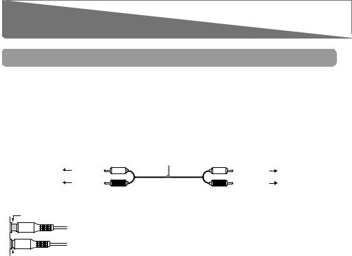
Connecting to the audio connector
Before connecting
•Do not connect the unit’s AC power cord (mains lead) to a wall outlet (the mains) until you have completed all the other connections, including 
 and AC OUTLET connections on page 11 and “Connecting speaker systems” on page 15.
•On each pair of connectors, a red connector (marked R) corresponds to the right channel, and a white connector (marked L) to the left channel. Connect white plugs of audio connection cables to L connectors and connect red plugs of audio connection cables to R connectors.
•Please refer to the instruction manual for each component when you make any connections.
|
|
Audio connection cable |
|
To L connector |
(White) |
(White) |
To L connector |
To R connector |
(Red) |
(Red) |
To R connector |
• Insert the plug securely. If the connection is incomplete, noise or malfunction may result.
Improper connection
 Insert completely
•When you use a digital audio optical cable, do not bend it sharply nor coil it tightly.
•Bundling an audio connection cable with the power cord or speaker cord may degrade the sound quality.
•Be sure to use the 
 cable, supplied with each component (except for the A-905TX) to connect to the
 remote control connector. If the connection is incomplete, you will be unable to operate the device using the remote controller.
•CD players and MD recorders use heat-sensitive parts. Do not place them on top of the amplifier.
To connect both the MD recorder MD-105TX and stereo cassette tape deck K-505TX to the unit:
Connect the MD recorder to the unit following the “Connections for combination example 2” on the next page and connect the stereo cassette tape deck to the unit following the “Connections for combination example 1.”
The 230-240 V model is shown in the following illustrations.
8

Connections for combination example 1
|
|
|
|
OUT(REC) |
IN (PLAY) |
|
|
|
|
|
|
|
|
|
|
OUT(REC) IN (PLAY) |
|
L |
|
|
OUTPUT |
|
|
L |
L |
|
CAUTION: |
||
|
|
|
L |
L |
|
|
|||
|
|
|
|
|
|
|
|
|
SPEAKERS |
|
|
|
|
OUTPUT |
|
R |
R |
|
|
|
|
|
|
REMOTE |
|
|
|
REMOTE |
|
|
|
|
|
CONTROL |
|
TUNER LINE/DVD |
TAPE |
CONTROL |
R |
|
|
|
L |
AC OUTLET |
|
OUT(REC) IN (PLAY) |
OUT (REC) |
IN (PLAY) |
|
L |
|
|
|
|
|
L |
|
|
|
ANTENNA |
FM |
R |
R |
R |
|
|
|
AC OUTLET |
|
|
|
75 |
|
R |
|
|
|
||
CDR/PC |
CD |
MD |
OUT |
IN |
SUBWOOFER |
PROCESSOR |
PRE OUT |
||||
|
|
TUNER LINE/DVD |
TAPE |
R |
Tuner (T-405TX) |
OUT(REC) IN (PLAY) |
OUT(REC) IN (PLAY) |
|
Amplifier |
||
|
L |
||
|
|
|
– this unit (A-905TX) |
|
|
R |
|
|
|
CDR/PC CD |
MD |
ANALOG |
OUTPUT |
|
|
INPUT |
OUTPUT |
|
ANALOG |
|
|
|
|
OUTPUT |
L |
AC OUTLET |
|
(REC) |
(PLAY) |
UNSWITCHED |
50Hz |
||||
|
AC 230-240V |
|
|
||
|
|
100W MAX. |
|
|
|
RREMOTE
CONTROL DIGITAL OUTPUT
L |
OPTICAL |
|
|
1 2 |
"CLASS 1 LASER |
L |
|
|
|
PRODUCT" |
|
|
|
|
D |
R |
|
|
R |
CD player (C-705TX) or CD changer (C-707CHX)
 : Signal flow
INPUT OUTPUT
(REC) (PLAY) REMOTE CONTROL
L
D
R
AC OUTLET
AC 230-240V 50 Hz UNSWITCHED 100W MAX.
Stereo cassette tape deck (K-505TX)
Connections for combination example 2
Tuner (T-405TX)
OUTPUT
OUTPUT
REMOTE
CONTROL
L |
AC OUTLET |
L |
ANTENNA |
75FM |
R |
|
R
ANALOG |
DIGITAL OUTPUT |
|
OUTPUT |
|
OPTICAL |
|
1 |
2 |
L
R
ANALOG
OUTPUT
LAC OUTLET
AC 230-240V 50Hz
50Hz
UNSWITCHED 100W MAX.
R |
REMOTE |
DIGITAL OUTPUT |
|
|
CONTROL |
|
|||
|
|
|
OPTICAL |
|
|
|
1 |
2 |
"CLASS 1 LASER |
PRODUCT"
OUT(REC) |
IN (PLAY) |
|
L |
|
L |
R |
|
R |
TUNER LINE/DVD |
TAPE |
|
OUT(REC) IN (PLAY) |
OUT(REC) IN (PLAY) |
|
L |
|
|
R |
|
|
CDR/PC |
CD |
MD |
ANALOG |
|
INPUT |
OUTPUT |
(REC) |
(PLAY) |
L |
L |
R |
R |
Amplifier
– this unit (A-905TX)
|
|
|
|
L |
|
|
|
|
CAUTION: |
L |
|
L |
|
|
|
|
|
SPEAKERS |
|
R |
|
R |
|
|
TUNER LINE/DVD |
TAPE |
|
|
R |
L |
|
|
|
|
R |
|
|
|
|
CDR/PC |
CD |
MD |
PROCESSOR |
SUBWOOFER |
PRE OUT |
DIGITAL INPUT
OPTICAL
1 |
2 |
ANALOG
INPUT |
OUTPUT |
REMOTE |
|
|
(REC) |
(PLAY) |
CONTROL |
DIGITAL INPUT |
|
L |
|
L |
|
OPTICAL |
|
1 |
2 |
||
R 
 R
R
CD player (C-705TX) |
|
MD recorder (MD-105TX) |
|
: Signal flow |
|
|
|
|
|
||
Optical cable |
|||
|
|||
Information Other Operation Preparations Connections using Before
9
 Loading...