


 Loading...
Manual No.
I66E-EN-01
VARISPEED F7
The Industrial Workhorse Model: CIMR-F7Z
200V Class 3-phase 0.4 to 110 kW
400V Class 3-phase 0.4 to 300 kW
Quick START GUIDE
English
Deutsch
Español
Français
Italiano
Português
Pyccкий
F7Z Quick Start Guide
Table of Contents
Warnings ...................................................................... |
EN-2 |
Safety Precautions and Instructions ........................................................................... |
EN-3 |
EMC Compatibility ...................................................................................................... |
EN-4 |
Installation .................................................................... |
EN-6 |
Mechanical Installation ............................................................................................... |
EN-6 |
Electrical Connection .................................................................................................. |
EN-8 |
Wiring Main Circuit Inputs ........................................................................................ |
EN-12 |
Keypad Operation ...................................................... |
EN-14 |
Digital Operator Display (optional) ............................................................................ |
EN-14 |
Power Up and Basic Parameter Setup ..................... |
EN-15 |
Start Up Procedure .................................................................................................. |
EN-15 |
Before Power Up ...................................................................................................... |
EN-16 |
Display after Power Up ............................................................................................. |
EN-16 |
Autotuning ................................................................................................................ |
EN-16 |
User Parameter .......................................................... |
EN-18 |
Troubleshooting ......................................................... |
EN-22 |
General Faults and Alarms ....................................................................................... |
EN-22 |
Operator Programming Errors .................................................................................. |
EN-24 |
Autotuning Faults ..................................................................................................... |
EN-24 |

Warnings |

 CAUTION
Cables must not be connected or disconnected, nor signal tests carried out,
while the power is switched on.
The Varispeed F7 DC bus capacitor remains charged even after the power has been switched off. To avoid an electric shock hazard, disconnect the frequency inverter from the mains before carrying out maintenance. Then wait for at least 5 minutes after all LEDs have gone out.
Do not perform a withstand voltage test on any part of the Varispeed. The frequency inverter contains semiconductors, which are not designed for such high voltages.
Do not remove the digital operator while the mains supply is switched on. The printed circuit board must also not be touched while the inverter is connected to the power.
Never connect general LC/RC interference suppression filters, capacitors or overvoltage protection devices to the inverter input or output.
To avoid unnecessary overcurrent faults, etc. being displayed, the signaling contacts of any contactor or switch fitted between inverter and motor must be integrated into the inverter control logic (e.g. baseblock).
This is absolutely imperative!
This manual must be read thoroughly before connecting and operating the inverter. All safety precautions and instructions for use must be followed.
The inverter may must be operated with the appropriate line filters, following the installation instructions in this manual and with all covers closed and terminals covered.
Only then will adequate protection be provided. Please do not connect or operate any equipment with visible damage or missing parts. The operating company is responsible for any injuries or equipment damage resulting from failure to heed the warnings in this manual.
EN-2

Safety Precautions and Instructions
General
Please read these safety precautions and instructions for use thoroughly before installing and operating this inverter. Also read all of the warning signs on the inverter and ensure they are never damaged or removed.
Live and hot inverter components may be accessible during operation. Removal of housing components, the digital operator or terminal covers runs the risk of serious injuries or damage in the event of incorrect installation or operation. The fact that frequency inverters control rotating mechanical machine components can give rise to other dangers.
The instructions in this manual must be followed. Installation, operation and maintenance may only be carried out by qualified personnel. For the purposes of the safety precautions, qualified personnel are defined as individuals who are familiar with the installation, starting, operation and maintenance of frequency inverters and have the proper qualifications for this work. Safe operation of these units is only possible if they are used properly for their intended purpose.
The DC bus capacitors can remain live for about 5 minutes after the inverter is disconnected from the power. It is therefore necessary to wait for this time before opening its covers. All of the main circuit terminals may still carry dangerous voltages.
Children and other unauthorized persons must not be allowed access to these inverters.
Keep these Safety Precautions and Instructions for Use readily accessible and supply them to all persons with any form of access to the inverters.
Intended Use
Frequency inverters are intended for installation in electrical systems or machinery.
Their installation in machinery and systems must conform to the following product standards of the Low Voltage Directive:
EN 50178, 1997-10, Equipping of Power Systems with Electronic Devices
EN 60204-1, 1997-12Machine Safety and Equipping with Electrical Devices
Part 1: General Requirements (IEC 60204-1:1997)/
Please note: Includes Corrigendum of September 1998
EN 61010-1, A2, 1995Safety Requirements for Information Technology Equipment
(IEC 950, 1991 + A1, 1992 + A2, 1993 + A3, 1995 + A4, 1996, modified)
CE marking is carried out to EN 50178, using the line filters specified in this manual and following the appropriate installation instructions.
Transportation and storage
The instructions for transportation, storage and proper handling must be followed in accordance with the technical data.
Installation
Install and cool the inverters as specified in the documentation. The cooling air must flow in the specified direction. The inverter may therefore only be operated in the specified position (e.g. upright). Maintain the specified clearances. Protect the inverters against impermissible loads. Components must not be bent nor insulation clearances changed. To avoid damage being caused by static electricity, do not touch any electronic components or contacts.
EN-3

Electrical Connection
Carry out any work on live equipment in compliance with the national safety and accident prevention regulations. Carry out electrical installation in compliance with the relevant regulations. In particular, follow the installation instructions ensuring electromagnetic compatibility (EMC), e.g. shielding, grounding, filter arrangement and laying of cables. This also applies to equipment with the CE mark. It is the responsibility of the manufacturer of the system or machine to ensure conformity with EMC limits.
Your supplier or Omron Yaskawa Motion Control representative must be contacted when using leakage current circuit breaker in conjunction with frequency inverters.
In certain systems it may be necessary to use additional monitoring and safety devices in compliance with the relevant safety and accident prevention regulations. The frequency inverter hardware must not be modified.
Notes
The Varispeed F7 frequency inverters are certified to CE, UL, and cUL
EMC Compatibility
Introduction
This manual was compiled to help system manufacturers using OMRON YASKAWA Motion Control (OYMC) frequency inverters design and install electrical switch gear. It also describes the measures necessary to comply with the EMC Directive. The manual's installation and wiring instructions must therefore be followed.
Our products are tested by authorized bodies using the standards listed below.
Product standard: EN 61800-3:1996
EN 61800-3; A11:2000
Measures to Ensure Conformity of OYMC Frequency inverters to the EMC Directive
OYMC frequency inverters do not necessarily have to be installed in a switch cabinet.
It is not possible to give detailed instructions for all of the possible types of installation. This manual therefore has to be limited to general guidelines.
All electrical equipment produces radio and line-borne interference at various frequencies. The cables pass this on to the environment like an aerial.
Connecting an item of electrical equipment (e.g. drive) to a supply without a line filter can therefore allow HF or LF interference to get into the mains.
The basic countermeasures are isolation of the wiring of control and power components, proper grounding and shielding of cables.
A large contact area is necessary for low-impedance grounding of HF interference. The use of grounding straps instead of cables is therefore definitely advisable.
Moreover, cable shields must be connected with purpose-made ground clips.
EN-4
Laying Cables
Measures Against Line-Borne Interference:
Line filter and frequency inverter must be mounted on the same metal plate. Mount the two components as close to each other as possible, with cables kept as short as possible.
Use a power cable with well-grounded shield. For motor cables up to 50 meters in length use shielded cables. Arrange all grounds so as to maximize the area of the end of the lead in contact with the ground terminal (e.g. metal plate).
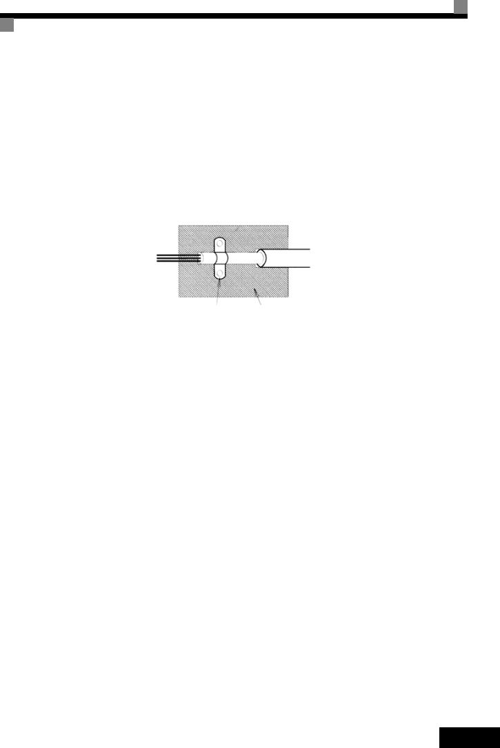
Shielded Cable:
•Use a cable with braided shield.
•Ground the maximum possible area of the shield. It is advisable to ground the shield by connecting the cable to the ground plate with metal clips (see following figure).
Ground Clip |
Ground Plate |
Fig 1 Earthing the cable shield with metal clips
The grounding surfaces must be highly conductive bare metal. Remove any coats of varnish and paint.
–Ground the cable shields at both ends.
–Ground the motor of the machine.
EN-5

Installation |
Mechanical Installation |
Unpacking the Inverter
Check the following items after unpacking the inverter.
Item |
Method |
|
Has the correct Inverter model been |
Check the model number on the nameplate on the side of the |
|
delivered? |
Inverter. |
|
|
|
|
Is the Inverter damaged in any way? |
Inspect the entire exterior of the Inverter to see if there are any |
|
scratches or other damage resulting from shipping. |
||
|
||
|
|
|
Are any screws or other components |
Use a screwdriver or other tools to check for tightness. |
|
loose? |
||
|
||
|
|
If any irregularities in the above items are found, contact the agency from which the Inverter was purchased or your Omron Yaskawa Motion Control representative immediately.
Checking the Installation Site
Protection covers are attached to the top and bottom of the NEMA 1 / IP20 Inverters. Be sure to remove the top cover before operating a 200 or 400 V Class Inverter with a capacity of 18.5 kW or less inside a panel.
Observe the following precautions when mounting the Inverter:
•Install the Inverter in a clean location which is free from oil mist and dust. It can be installed in a totally enclosed panel that is completely shielded from floating dust.
•When installing or operating the Inverter, always take special care so that metal powder, oil, water, or other foreign matter does enter the Inverter.
•Do not install the Inverter on combustible material, such as wood.
•Install the Inverter in a location free from radioactive materials and combustible materials.
•Install the Inverter in a location free from harmful gasses and liquids.
•Install the Inverter in a location without excessive oscillation.
•Install the Inverter in a location free from chlorides.
•Install the Inverter in a location without direct sunlight.
EN-6

Installation Orientation
Install the Inverter vertically so as not to reduce the cooling effect. When installing the Inverter, always provide the following installation space to allow normal heat dissipation.
A |
|
30mm min. |
30mm min. |
50mm |
|
min. |
|
Horizontal Space
B |
Air |
120mm min. |
Air |
Vertical Space |
|
A |
B |
|
200V class inverter, 0.55 to 90 kW |
50 mm |
120 mm |
|
400V class inverter, 0.55 to 132 kW |
|||
|
|
||
|
|
|
|
200V class inverter, 110 kW |
120 mm |
120 mm |
|
400V class inverter, 160 to 220 kW |
|||
|
|
||
|
|
|
|
400V class inverter, 300 kW |
300 mm |
300 mm |
Fig 2 Installation space
1. The same space is required horizontally and vertically for IP00, IP20 and NEMA 1 Inverters.
2. Always remove the top protection cover after installing an Inverter with an output of 18.5 kW or less in a
|
panel. |
|
IMPORTANT |
Always provide enough space for suspension eye bolts and the main circuit lines when installing an |
|
Inverter with an output of 22 kW or more in a panel. |
||
|
Installation of Inverters and EMC filters
For an EMC rules compliant installation consider the following points:
•Use a line filter.
•Use shielded motor cables.
•Mount the inverter and filter on a grounded cunductive plate.
•Remove any paint or dirt before mounting the parts in order to reach the lowest possible grounding impedance.
Fig 3 EMC filter installation
PE L2
L1 L3 Ground Bonds
Remove any paint!
PE
Line
Inverter
Filter
Load |
L2 |
V |
|
GND L1 L3 U |
W GND |
Cable Lenght
as short as possible
Grounded
Metal Plate
Screened
Motor cable
Ground Bonds
Remove any paint!
M
~3
EN-7
Loading...