


741WHNT
Page 1
MODELS 741BRNT • 741SNNT • 741WHNT • 741BRFLNT • 741WHFLNT
DECORATIVE SERIES
CEILING VENTILATORS
READ AND SAVE THESE INSTRUCTIONS
!
WARNING
TO REDUCE THE RISK OF FIRE, ELECTRIC SHOCK, OR IN-
JURY TO PERSONS, OBSERVE THE FOLLOWING:
1. Use this unit only in the manner intended by the manufacturer. If
you have questions, contact the manufacturer at the address or
telephone number listed in the warranty.
2. Before servicing or cleaning unit, switch power off at service panel
and lock the service disconnecting means to prevent power from
being switched on accidentally. When the service disconnecting
means cannot be locked, securely fasten a prominent warning
device, such as a tag, to the service panel.
3. Installation work and electrical wiring must be done by a quali-
fied person(s) in accordance with all applicable codes and stan-
dards, including fire-rated construction codes and standards.
4. Sufficient air is needed for proper combustion and exhausting of
gases through the flue (chimney) of fuel burning equipment to
prevent backdrafting. Follow the heating equipment
manufacturer’s guideline and safety standards such as those
published by the National Fire Protection Association (NFPA),
and the American Society for Heating, Refrigeration and Air Con-
ditioning Engineers (ASHRAE), and the local code authorities.
5. When cutting or drilling into wall or ceiling, do not damage elec-
trical wiring and other hidden utilities.
6. Ducted fans must always be vented to the outdoors.
WARNING
7. NEVER place a switch where it can be reached from a tub or
shower.
8. Fluorescent models only: Do not use a dimmer switch to con-
trol the light of this unit.
9. This unit must be grounded.
10. This unit is U.L. listed. Type I.C. inherently protected.
CAUTION
1. For general ventilating use only. Do not use to exhaust hazard-
ous or explosive materials and vapors.
2. This product is designed for ceiling installation only. This prod-
uct is designed for installation in ceilings up to a 12/12 pitch.
Ductwork must point up. DO NOT MOUNT THIS PRODUCT IN
A WALL.
3. The light fixture assembly must be mounted to the fan housing
assembly included with this product. Do not mount the light
fixture assembly to a wiring outlet box.
4. To avoid motor bearing damage and noisy and/or unbalanced
impellers, keep drywall spray, construction dust, etc. off power
unit.
5. Please read specification label on product for further informa-
tion and requirements.
Installer: Leave this manual with the homeowner.
Homeowner: Use and Care information on page 4.
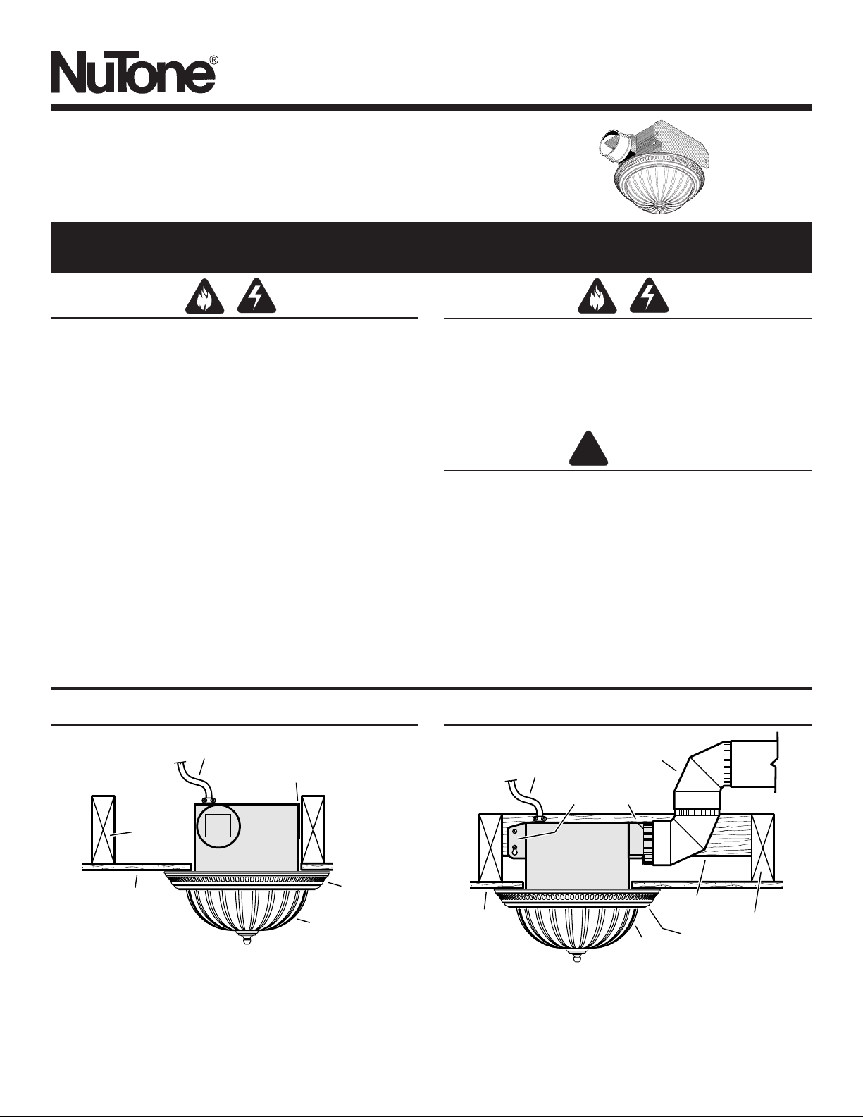
TYPICAL INSTALLATIONSTYPICAL INSTALLATIONS
16”-ON-CENTER CEILING JOISTS
Housing mounted directly to joist.
HOUSING
CEILING
JOIST
MOUNTING TABS
CEILING
MATERIAL
POWER CABLE
GRILLE
PAN
GLASS
LIGHT SHADE
HOUSING
CEILING
JOIST
MOUNTING TABS
CEILING
MATERIAL
POWER CABLE
4" ROUND
DUCT
ADDITIONAL
FRAMING
GRILLE
PAN
GLASS
LIGHT SHADE
24”-ON-CENTER CEILING JOISTS
Housing mounted to additional framing.
Page 2
MODELS 741BRNT • 741SNNT • 741WHNT • 741BRFLNT • 741WHFLNT
TYPICAL INSTALLATIONS
(continued)
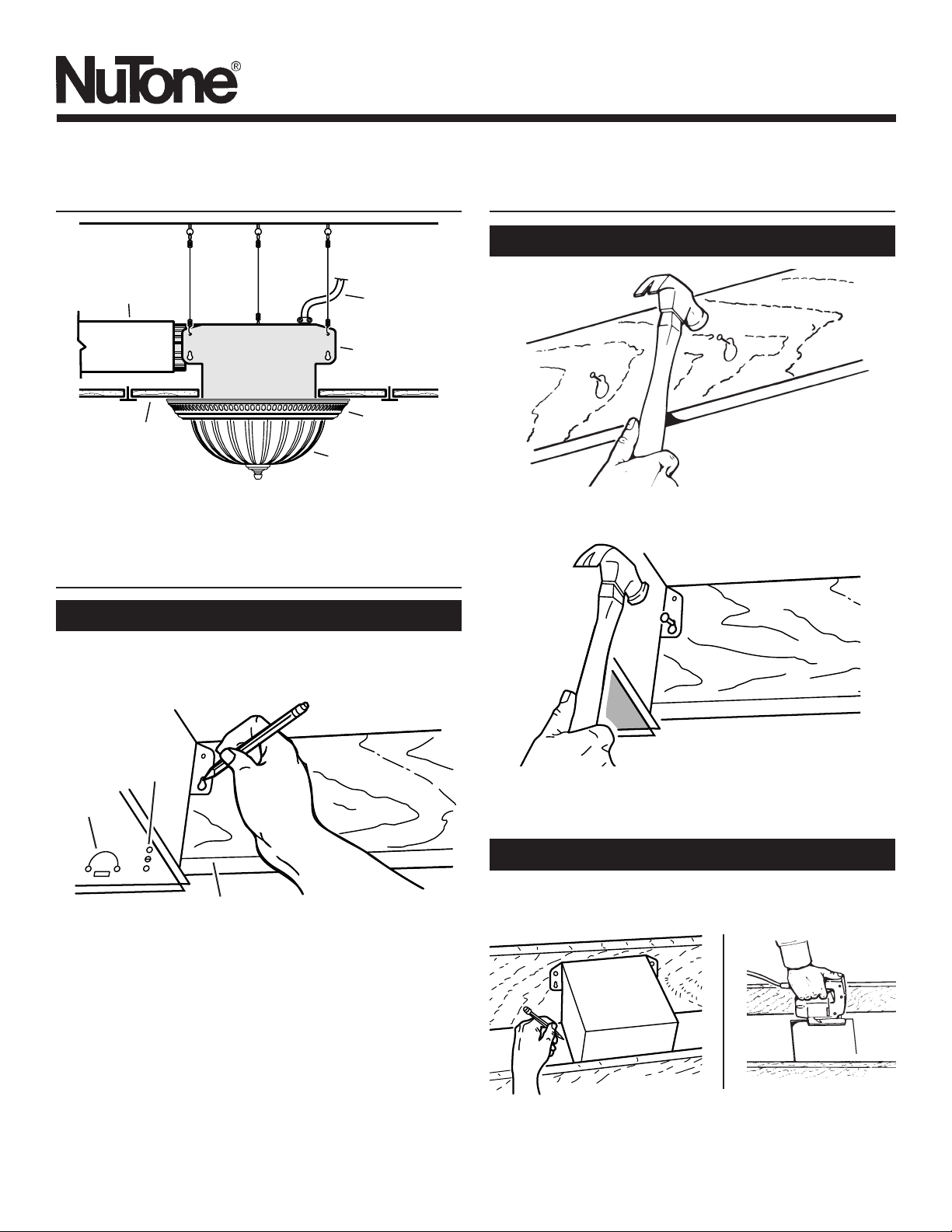
SUSPENDED CEILINGS
Housing hung with wires - 3-point mount.
INSTALL THE HOUSING
1. Choose the location for your fan/light in the ceiling. For
best possible performance, use the shortest possible duct
run and a minimum number of elbows.
2. Position mounting brackets against joist so that bottom
edge of housing will be flush with finished ceiling.
Additional positioning feature for 5/8”, 1”, &
1-1/4” thick ceiling material:
Holes in corners of housing are labeled with
various ceiling material thicknesses. Position
housing so bottom edge of joist is visible through
a matched set of holes. The housing is now in the
proper position for that ceiling material thickness.
Additional positioning feature for 1/2” thick
ceiling material:
Bend two tabs, on side of housing,
90
0
outward. Lift
housing until tabs contact underside of joist.
Mark the keyhole slot on both mounting brackets.
3. Set housing aside and drive nails partially into joist at the
top of both keyhole marks.
4. Hang housing from nails and pound nails tight. To ensure
a noise-free mount, pound another nail through the top
hole of each mounting tab.
New Construction
INSTALL THE HOUSING
(continued)
New Construction
Existing Construction
2. In attic, position mounting brackets against joist. Trace
outline of housing on ceiling material.
1. Choose the location for your fan/light in the ceiling. For
best possible performance, use the shortest possible duct
run and a minimum number of elbows.
5/8
1
1-1/4
TAB
HOLES
BOTTOM EDGE OF JOIST
3. Set housing aside and cut ceiling opening slightly larger
than marked.
MOUNTING
TAB
GRILLE
PAN
SUSPENDED
CEILING
MATERIAL
POWER
CABLE
4" ROUND
DUCT
HOUSING
GLASS
LIGHT SHADE
 Loading...